9.1 The Loop Plant Environment
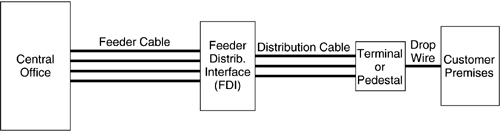
| POTS is provisioned to customers by routing twisted wire-pairs between the telephone network equipment at a central office (CO) or remote terminal (RT) and the customer premises (CP) location. The twisted wire pair that connects the CO to the CP is the subscriber loop, which may consist of sections of copper twisted wire pairs of one or more different gauges. Twisted wire pairs are contained in cables that have large cross sections near the central office. Within each cable, the twisted wire pairs are grouped into binders of 10, 25, or up to 50 wire pairs, and there could be up to 50 binder groups per cable. Figure 9.1 shows the basic architecture of the loop plant, in which subscriber loops are provisioned. Each subscriber loop can be divided into three portions of cable: feeder cable, distribution cable, and drop wire. Feeder cables provide links from the CO to a connection point or feeder distribution interface (FDI) in a concentrated customer area. Distribution cables provide links from the FDI to customer locations. The FDI provides connections of the wire pairs in the feeder cable with those in the distribution cable. The drop wires represent the portion of wire that extends from the terminal on a telephone pole to the customer premises or underground from the pedestal to the customer premises. Figure 9.1. Architecture of the loop plant. Because loop plant construction is completed prior to service request, distribution cables are made available to all existing and potential customer sites. It is common practice to connect a twisted pair from a feeder cable to more that one wire pair in the distribution cable. Multiple connections from a feeder or distribution cable to more than one-customer premises form bridged taps. Typically, only one customer is serviced at one time while the other bridged taps are unterminated. Bridged taps provide the ability for cable pairs to be connected to any customer site passed by the cable, and they exist on about 80 percent of loops in the United States and Canada. Bridged taps also exist in the loop plant of many countries , though generally at a much lower proportion than found in North America. The loop plant was originally designed to provision customers with POTS. To ensure proper quality of service, design rules were defined for subscriber loop provisioning. One set of rules that governs distribution of twisted wire pairs for voice service from the CO to the CP is the resistance design rules. Implemented in the 1980 “1981 time frame (a very small portion of the current loop plant), the design rules are summarized as follows :
Revised resistance design (RRD) rules are defined in [11]. The majority of CO-fed loops in the United States follow the RRD rules. These rules require that the maximum loop resistance on an 18 kft twisted wire pair between the central office to the customer premises must be less than 1300 Ohms and on loops between 18 kft and 24 kft, the maximum resistance is 1500 Ohms. Loading coils are applied to all loops greater than 18 kft or have loop resistance greater than 1300 Ohms. Table 9.1 provides an example of the typical RRD design loops for various distances; loops shorter than 15.3 kft are entirely 26 AWG wire. The numbers in the wire-gauge columns indicate the length of that type of wire in kilofeet. Telephone cables are designed with different wire gauges ranging from 26 AWG (thin diameter resulting in higher resistance per unit length) to 19 AWG (thick diameter resulting in lower resistance per unit length). Because distances from the CO to each customer are different, distribution cables are equipped with different wire gauges to meet the resistance design guidelines and provide service to the maximum number of customers. On long loops, the distribution cables tend to use thicker gauge wire in the regions closer to the subscriber location in order to minimize the total loop resistance. At the CO, the feeder cables tend to use fine diameter gauges (typically 26 AWG) to maximize the number of wire pairs being served by the central office. Some customers may be located so far away from the CO that it may not be possible to meet the resistance design rules. If a subscriber loop is provisioned with a length greater than the maximum defined by the RRD rules, then loading coils must be inserted in the loop to achieve proper voice quality. Note, however, that subscriber loops provisioned with loading coils are not suitable for support of wide- band DSL services because loading coils introduce too much attenuation of the frequencies above the voice channel, which are required by the DSL system. In short, loading coils must be removed from any subscriber loop that is to support a DSL based service. Another set of rules, called carrier serving area (CSA) rules, define the distribution of twisted wire pairs from digital loop carrier systems. The radius covered by CSA rules are up to 9000 ft of 26-gauge wire and up to 12,000 ft on 24-gauge wire. The concept of CSA rules were originally developed for provisioning loops from digital loop carrier (DLC) systems in support 56 kb/s digital data service (DDS) and later slightly modified for the support of POTS from a DLC system. The CSA rules are defined as follows:
The above CSA guidelines do not include any wiring in the CO nor any drop wiring and any wiring in the customer premises. As the transport medium for wide-band signals, the twisted wire pairs introduce linear impairments into the signal. Specifically, the linear impairments are propagation loss, amplitude distortion, and delay distortion. The propagation loss in dB is directly proportional to the distance of the loop. Amplitude distortion results from the fact that signal components at higher frequencies experience more amplitude loss than the components at low frequencies. To a first order, the amplitude response of the twisted wire pair channel rolls off at roughly the square root of frequency. Finally, the delay is such that at low frequencies (less than approximately 10 kHz) there is very sharp variation in the group delay and at higher frequencies the delay response is relatively constant [1]. Test loops have been developed for American Wire Gauge (AWG) in T1E1.4 and metric cables in ETSI for ISDN [3 “4], HDSL [5 “7, 14], and ADSL [2, 15, 16] systems. These test loops provide an industry-accepted basis for evaluating the performance of the various DSL systems in the presence of different crosstalk scenarios. Reference [1] provides a detailed description of cable modeling. References [2 “7] provide a comprehensive list of the test loops used for the North American and European loop environments. |
 .
. | Top |
EAN: 2147483647
Pages: 154