11.5 MIMO Channel Identification
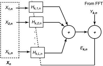
| All the methods for multiuser coordination need information about the multiple-input multiple-output (MIMO) channel, H ( f ) or its magnitude H ( f ) and/or the the noise spectra on each line's output. This information may be derived by each line itself without coordination. However, coordination may allow more swift and easy determination of the characteristics. With no coordination, the identification of crosstalking coupling into a specific channel is called "blind" training as the data sequences on other lines are unknown. When these sequences are known either through coordination or because a regularly inserted synchronization pattern on another line has been identified, the DSM system "uses training" or simply is "not blind." Level 3 coordination is the easiest for channel identification and noise spectral estimation and is discussed in Subsection 11.5.1. Essentially special training sequences can be used to allow easy and accurate identification of every possible cross coupling between the lines, with any remaining noise typically modeled as Gaussian and identified easily by removing crosstalk and measuring the spectrum of the residual error. Some systems may instead only allow input/output packets of a channel to be available at certain points in time to the network maintenance center (data acquisition unit in Figure 11.6). Then the methods in Subsection 11.5.1 can be used with some additional processing as described in Subsection 11.5.2. Absence of coordination or information acquisition forces the blind methods of Subsection 11.5.3, which are effective but can take much longer to train. 11.5.1 Method of Least SquaresLevel 2 coordination likely will occur only with synchronized DMT systems in the binder group , which fortunately then means that each tone sees or provides crosstalk from other users only on exactly that same tone. This leads to enormous simplification in channel identification. Each modem can use a known 4-pt QAM training sequence that has been randomly generated for robustness and low PAR. The current patterns used in ADSL and VDSL are sufficient. Different lines will need to have a different phase (achieved by bit-level staggering of that sequence by one DMT symbol from each line to the next ). The adaptive combiner shown in Figure 11.40 is implemented for each tone, with no more than 4 coefficients (as other crosstalkers are much smaller) that should provide nonzero crosstalk coefficients H km,n on the n th tone. Training may take longer than for a single modem and can be implemented by a least-squares fit over S training symbols as Figure 11.40. Adaptivechannel (per tone) for L users. Values in H k,n that have magnitude below some threshold (or relative threshold) can be ignored in subsequent signal processing (with Level 2 coordination). A simple LMS gradient algorithm (see [1]) can instead be used if the above matrix aversion is to be avoided, and is illustrated in Figure 11.40 according to The procedure is greatly facilitated in the case of Level 3 coordination, which is also the one of the few cases in which the full (gain and phase) H k,n is desirable with Level 3 coordination, and H k,n is needed to set either the GDFE or precoder coefficients. It is sometimes also necessary with MUD methods as discussed in the appendix. In this case, coordinated known training is highly unlikely to occur and so identification becomes more complicated (at least conceptually) and is discussed in Section 11.5.2. Noise spectrum estimation proceeds for tone n of user k by forming the error sequence and, for example, computing an average spectrum value at each frequency n and each line output k according to 11.5.2 PacketizationLevels 0 “2 coordination does not admit a known training pattern on all lines, thus complicating the procedure. Sometimes a multiuser system might benefit from knowing the full H also, in particular, some of the MUD methods in the appendix. DSM standardization efforts [26] describe the methods for collecting either type of data. Level 2 data acquisition simply implies that a DSL modem has the ability to release SNR ( f = n / T ) for that line in DSM standards, whereas Level 3 data acquisition implies that input/output packet characterizations of the channel (with either live [5] or training data) are available. Level 3 data acquisition can occur even when Level 3 coordination is not possible because the input/output packets can be released over short periods of time to the acquisition unit with need for line-signal coordination.
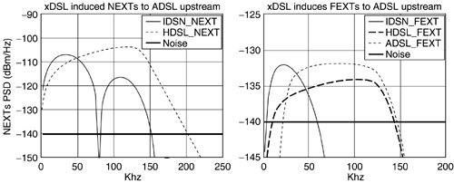
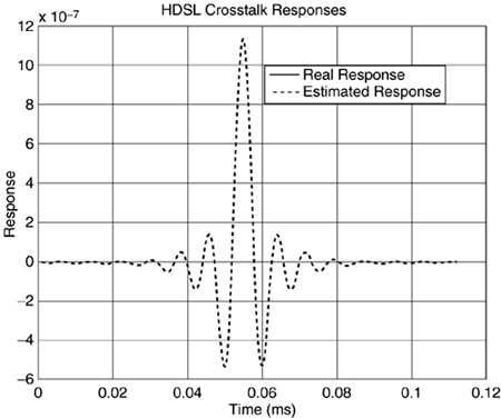
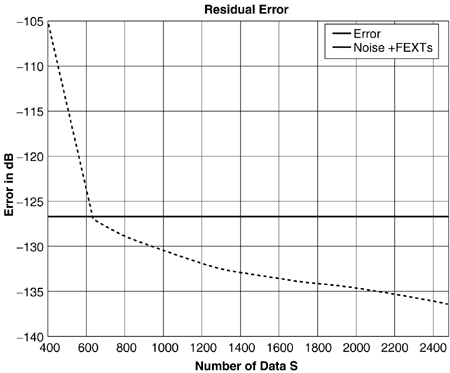
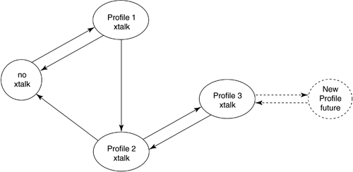
Virtual Binder Group Identification and AlignmentLevel 3 data collection provides I/O DSL packet data at specified times of operation of a DSL line. The first issue then is the time stamping and collection. An information-acquisition unit specifies a time of operation approximately around which the DSL modem collects S successive packets of DSL I/O information and provides to the acquisition unit for later use in processing. The approximate time is established through the network clock (or any reasonably accurate clock). Presumably, the information-acquisition unit requests data from several modems in the same binder at about the same time. Knowledge of the input and output packets then enables isolation of the important crosstalkers (i.e., those that are large) for any given line through cross-correlation with the various other lines' input sequences. Such cross-correlation is computed by which will have a maximum over the "lag" index and reinterpolating the input of the oppositive channel to this offset for a few exact values in the vicinity of the original average value InterpolationInterpolation among non-level-3 “coordinated DMT systems leads to the structure of Figure 11.40 and the phase-locking and virtual-binder-group identification of the previous subsection. Typically these systems all have 4.3125 kHz tone spacing (whether VDSL, ADSL, or SDSL) and thus interpolation is not necessary and corresponding tones are aligned. For mixes of any other combination of DSL, interpolation between sampling rates is required. The vector H k represents the contribution of every DSL system input (over several time samples with a packet, or over several tones when a DMT system) from an input packet into the corresponding packet at the output of the k th line. The structure of Figure 11.40 is still applicable , except that many input samples from each of the lines and many output samples for the k th line appear. Thus, no special interpolation procedure is required other than knowing which samples on each input (and how many) contribute to each of the outputs. The time-domain signal in the cross-correlation x ( t ) must be constructed at approximately the sampling rate of the receiver. There are many methods for such interpolation from the same data supplied at another sampling rate. Typically, this is facilitated if input/output samples are supplied at sampling rates two or more times higher than the actual symbol rate of time-domain (PAM and QAM) signals, allowing linear interpolation between samples to often be sufficient. (For DMT systems, interpolation is easy in the frequency domain ”see [1] and the data need not be oversampled.) This book does not contribute further to the considerable literature on interpolation via digital signal processing. Zeng has provided an example in Figures 11.41 “11.43 where Level 3 data acquisition has been used (presumably for Level 0 “2 coordination, not Level 3 coordination, otherwise the methods of Section 11.A would be used directly). The line of interest is one of the ADSL signals. Here, 4 basic-rate ISDN, 4 HDSLs, and 5 ADSLs all share the same binder with significant mutual cross talking. The spectra of the crosstalkers appear in Figure 11.41, while the cross-correlation with one of the HDSLs appears in Figure 11.42. Note the shape is the same as that of the crosstalk coupling channel response and has a definite peak identifying the timing offset between the two signals. Finally Figure 11.43 shows the resulting error magnitude as the number of training symbols increases . After a few hundred packets of training, the residual error is acceptably small. For more on these methods, see Zeng and Cioffi [27]. Figure 11.41. Crosstalker spectra into an upstream ADSL. Figure 11.42. Cross-correlation for identification of offset between one of the HDSLs and the ADSL. Figure 11.43. Estimation error for channel identification procedure. Channel state machines as in the appendix and Figure 11.45 can be used to monitor state changes between different signals for the situation where different DSLs are turning on and off. A coupling function can only be identified when the corresponding DSL is energized. Figure 11.45. Profiling state machine. 11.5.3 Blind TrainingWithout Level 3 data acquisition, the DSL system on each line must identify crosstalkers "blindly" if MUD methods are to be used by that line (more advanced methods than MUD are necessarily not available if there is no Level 3 coordination nor data acquisition). The lack of coordination complicates channel identification. This area has been studied by Aldana and Cioffi [9]. Initially, the conception of blind training proceeds with the least-squares concept of Section 11.5.1. The least-squares solution could theoretically be recomputed for every possible transmitted data sequence and then that sum of squared errors that is smallest over all such calculations corresponds to a value of the matrix H that is the maximum- likelihood estimate of the matrix channel. It is not possible to do better than this estimate. However, clearly the number of possible sequences even with the per-tone reductions of DMT could simply be too numerous to compute. A possibility is to iteratively compute this estimate by construction of the probability density of the joint input sequence and channel matrix. This is an area of active research for many in wireless transmission and could prove fruitful when applied to DSL, but has not been fully investigated at this time. However, Aldana has studied one version of such iterative estimation/decoding which is the well-known expectation maximization (EM) method [9]. In this case, the average value over all possible transmitted sequences is precomputed or estimated in the least-squares equation. This essentially maximizes the likelihood function on average. It is still somewhat complex, but possible to do most of the difficult computation off-line and store it for many uses. The interested reader is referred to [9] for a detailed analysis and description of Aldana and Cioffi's EM method for DSL where it is shown to be unusually effective in identifying the matrix channel blindly. Work to simplify calculations further is likely to occur by groups interested in transmission systems that do not have Level 2 coordination of signals and cannot implement sharing methods in a distributed manner. Fortunately, distributed-iterative water-filling eliminates the need to know the channel in all places so it is only those systems that must know it for multiuser detection that would need to use the EM algorithm. |
| Top |
EAN: 2147483647
Pages: 154
 10)used. If this maximum exceeds a threshold, typically set as a function of the received signal