Section 7.1. Placement of Encryption Function
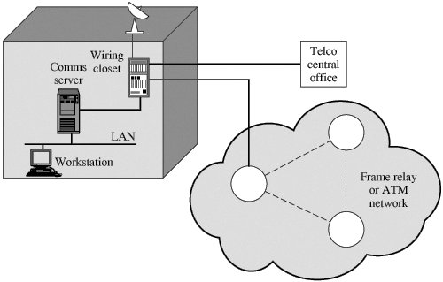
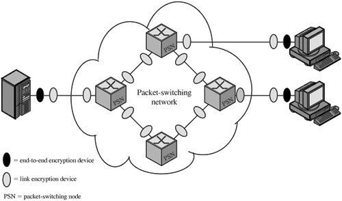
7.1. Placement of Encryption FunctionIf encryption is to be used to counter attacks on confidentiality, we need to decide what to encrypt and where the encryption function should be located. To begin, this section examines the potential locations of security attacks and then looks at the two major approaches to encryption placement: link and end to end. Potential Locations for Confidentiality AttacksAs an example, consider a user workstation in a typical business organization. Figure 7.1 suggests the types of communications facilities that might be employed by such a workstation and therefore gives an indication of the points of vulnerability. Figure 7.1. Points of Vulnerability In most organizations, workstations are attached to local area networks (LANs). Typically, the user can reach other workstations, hosts, and servers directly on the LAN or on other LANs in the same building that are interconnected with bridges and routers. Here, then, is the first point of vulnerability. In this case, the main concern is eavesdropping by another employee. Typically, a LAN is a broadcast network: Transmission from any station to any other station is visible on the LAN medium to all stations. Data are transmitted in the form of frames, with each frame containing the source and destination address. An eavesdropper can monitor the traffic on the LAN and capture any traffic desired on the basis of source and destination addresses. If part or all of the LAN is wireless, then the potential for eavesdropping is greater. Furthermore, the eavesdropper need not necessarily be an employee in the building. If the LAN, through a communications server or one of the hosts on the LAN, offers a dial-in capability, then it is possible for an intruder to gain access to the LAN and monitor traffic. Access to the outside world from the LAN is almost always available in the form of a router that connects to the Internet, a bank of dial-out modems, or some other type of communications server. From the communications server, there is a line leading to a wiring closet. The wiring closet serves as a patch panel for interconnecting internal data and phone lines and for providing a staging point for external communications. The wiring closet itself is vulnerable. If an intruder can penetrate to the closet, he or she can tap into each wire to determine which are used for data transmission. After isolating one or more lines, the intruder can attach a low-power radio transmitter. The resulting signals can be picked up from a nearby location (e.g., a parked van or a nearby building). Several routes out of the wiring closet are possible. A standard configuration provides access to the nearest central office of the local telephone company. Wires in the closet are gathered into a cable, which is usually consolidated with other cables in the basement of the building. From there, a larger cable runs underground to the central office. In addition, the wiring closet may provide a link to a microwave antenna, either an earth station for a satellite link or a point-to-point terrestrial microwave link. The antenna link can be part of a private network, or it can be a local bypass to hook in to a long-distance carrier. The wiring closet may also provide a link to a node of a packet-switching network. This link can be a leased line, a direct private line, or a switched connection through a public telecommunications network. Inside the network, data pass through a number of nodes and links between nodes until the data arrive at the node to which the destination end system is connected. An attack can take place on any of the communications links. For active attacks, the attacker needs to gain physical control of a portion of the link and be able to insert and capture transmissions. For a passive attack, the attacker merely needs to be able to observe transmissions. The communications links involved can be cable (telephone twisted pair, coaxial cable, or optical fiber), microwave links, or satellite channels. Twisted pair and coaxial cable can be attacked using either invasive taps or inductive devices that monitor electromagnetic emanations. Invasive taps allow both active and passive attacks, whereas inductive taps are useful for passive attacks. Neither type of tap is as effective with optical fiber, which is one of the advantages of this medium. The fiber does not generate electromagnetic emanations and hence is not vulnerable to inductive taps. Physically breaking the cable seriously degrades signal quality and is therefore detectable. Microwave and satellite transmissions can be intercepted with little risk to the attacker. This is especially true of satellite transmissions, which cover a broad geographic area. Active attacks on microwave and satellite are also possible, although they are more difficult technically and can be quite expensive. In addition to the potential vulnerability of the various communications links, the various processors along the path are themselves subject to attack. An attack can take the form of attempts to modify the hardware or software, to gain access to the memory of the processor, or to monitor the electromagnetic emanations. These attacks are less likely than those involving communications links but are nevertheless a source of risk. Thus, there are a large number of locations at which an attack can occur. Furthermore, for wide area communications, many of these locations are not under the physical control of the end user. Even in the case of local area networks, in which physical security measures are possible, there is always the threat of the disgruntled employee. Link versus End-to-End EncryptionThe most powerful and most common approach to securing the points of vulnerability highlighted in the preceding section is encryption. If encryption is to be used to counter these attacks, then we need to decide what to encrypt and where the encryption gear should be located. As Figure 7.2 indicates, there are two fundamental alternatives: link encryption and end-to-end encryption. Figure 7.2. Encryption Across a Packet-Switching Network | ||||||||||||||||||||||||||||
Link Encryption | End-to-End Encryption |
|---|---|
Security within End Systems and Intermediate Systems | |
Message exposed in sending host | Message encrypted in sending host |
Message exposed in intermediate nodes | Message encrypted in intermediate nodes |
Role of User | |
Applied by sending host | Applied by sending process |
Transparent to user | User applies encryption |
Host maintains encryption facility | User must determine algorithm |
One facility for all users | Users selects encryption scheme |
Can be done in hardware | Software implementation |
All or no messages encrypted | User chooses to encrypt, or not, for each message |
Implementation Concerns | |
Requires one key per (host-intermediate node) pair and (intermediate node-intermediate node) pair | Requires one key per user pair |
Provides host authentication | Provides user authentication |
Logical Placement of End-to-End Encryption Function
With link encryption, the encryption function is performed at a low level of the communications hierarchy. In terms of the Open Systems Interconnection (OSI) model, link encryption occurs at either the physical or link layers.
For end-to-end encryption, several choices are possible for the logical placement of the encryption function. At the lowest practical level, the encryption function could be performed at the network layer. Thus, for example, encryption could be associated with the frame relay or ATM protocol, so that the user data portion of all frames or ATM cells is encrypted.
With network-layer encryption, the number of identifiable and separately protected entities corresponds to the number of end systems in the network. Each end system can engage in an encrypted exchange with another end system if the two share a secret key. All the user processes and applications within each end system would employ the same encryption scheme with the same key to reach a particular target end system. With this arrangement, it might be desirable to off-load the encryption function to some sort of front-end processor (typically a communications board in the end system).
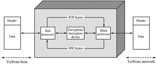
Figure 7.3 shows the encryption function of the front-end processor (FEP). On the host side, the FEP accepts packets. The user data portion of the packet is encrypted, while the packet header bypasses the encryption process.[1] The resulting packet is delivered to the network. In the opposite direction, for packets arriving from the network, the user data portion is decrypted and the entire packet is delivered to the host. If the transport layer functionality (e.g., TCP) is implemented in the front end, then the transport-layer header would also be left in the clear and the user data portion of the transport protocol data unit is encrypted.
[1] The terms red and black are frequently used. Red data are sensitive or classified data in the clear. Black data are encrypted data.
Figure 7.3. Front-End Processor Function
Deployment of encryption services on end-to-end protocols, such as a network-layer frame relay or TCP, provides end-to-end security for traffic within a fully integrated internetwork. However, such a scheme cannot deliver the necessary service for traffic that crosses internetwork boundaries, such as electronic mail, electronic data interchange (EDI), and file transfers.
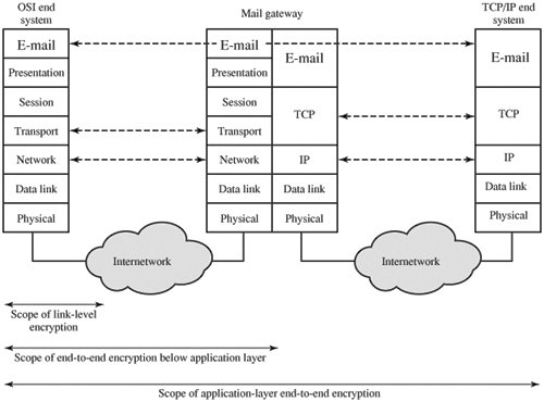
Figure 7.4 illustrates the issues involved. In this example, an electronic mail gateway is used to interconnect an internetwork that uses an OSI-based architecture with one that uses a TCP/IP-based architecture.[2] In such a configuration, there is no end-to-end protocol below the application layer. The transport and network connections from each end system terminate at the mail gateway, which sets up new transport and network connections to link to the other end system. Furthermore, such a scenario is not limited to the case of a gateway between two different architectures. Even if both end systems use TCP/IP or OSI, there are plenty of instances in actual configurations in which mail gateways sit between otherwise isolated internetworks. Thus, for applications like electronic mail that have a store-and-forward capability, the only place to achieve end-to-end encryption is at the application layer.
[2] Appendix H provides a brief overview of the OSI and TCP/IP protocol architectures.
Figure 7.4. Encryption Coverage Implications of Store-and-Forward Communications
A drawback of application-layer encryption is that the number of entities to consider increases dramatically. A network that supports hundreds of hosts may support thousands of users and processes. Thus, many more secret keys need to be generated and distributed.
An interesting way of viewing the alternatives is to note that as we move up the communications hierarchy, less information is encrypted but it is more secure. Figure 7.5 highlights this point, using the TCP/IP architecture as an example. In the figure, an application-level gateway refers to a store-and-forward device that operates at the application level.[3]
[3] Unfortunately, most TCP/IP documents use the term gateway to refer to what is more commonly referred to as a router.
Figure 7.5. Relationship between Encryption and Protocol Levels
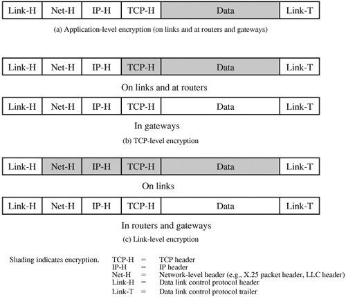
With application-level encryption (Figure 7.5a), only the user data portion of a TCP segment is encrypted. The TCP, IP, network-level, and link-level headers and link-level trailer are in the clear. By contrast, if encryption is performed at the TCP level (Figure 7.5b), then, on a single end-to-end connection, the user data and the TCP header are encrypted. The IP header remains in the clear because it is needed by routers to route the IP datagram from source to destination. Note, however, that if a message passes through a gateway, the TCP connection is terminated and a new transport connection is opened for the next hop. Furthermore, the gateway is treated as a destination by the underlying IP. Thus, the encrypted portions of the data unit are decrypted at the gateway. If the next hop is over a TCP/IP network, then the user data and TCP header are encrypted again before transmission. However, in the gateway itself the data unit is buffered entirely in the clear. Finally, for link-level encryption (Figure 7.5c), the entire data unit except for the link header and trailer is encrypted on each link, but the entire data unit is in the clear at each router and gateway.[4]
[4] The figure actually shows but one alternative. It is also possible to encrypt part or even all of the link header and trailer except for the starting and ending frame flags.
EAN: 2147483647
Pages: 209