[Page 622 (continued)]20.1. Firewall Design Principles Information systems in corporations, government agencies, and other organizations have undergone a steady evolution: Centralized data processing system, with a central mainframe supporting a number of directly connected terminals Local area networks (LANs) interconnecting PCs and terminals to each other and the mainframe Premises network, consisting of a number of LANs, interconnecting PCs, servers, and perhaps a mainframe or two
[Page 623]Enterprise-wide network, consisting of multiple, geographically distributed premises networks interconnected by a private wide area network (WAN) Internet connectivity, in which the various premises networks all hook into the Internet and may or may not also be connected by a private WAN
Internet connectivity is no longer optional for organizations. The information and services available are essential to the organization. Moreover, individual users within the organization want and need Internet access, and if this is not provided via their LAN, they will use dial-up capability from their PC to an Internet service provider (ISP). However, while Internet access provides benefits to the organization, it enables the outside world to reach and interact with local network assets. This creates a threat to the organization. While it is possible to equip each workstation and server on the premises network with strong security features, such as intrusion protection, this is not a practical approach. Consider a network with hundreds or even thousands of systems, running a mix of various versions of UNIX, plus Windows. When a security flaw is discovered, each potentially affected system must be upgraded to fix that flaw. The alternative, increasingly accepted, is the firewall. The firewall is inserted between the premises network and the Internet to establish a controlled link and to erect an outer security wall or perimeter. The aim of this perimeter is to protect the premises network from Internet-based attacks and to provide a single choke point where security and audit can be imposed. The firewall may be a single computer system or a set of two or more systems that cooperate to perform the firewall function. In this section, we look first at the general characteristics of firewalls. Then we look at the types of firewalls currently in common use. Finally, we examine some of the most common firewall configurations. Firewall Characteristics [BELL94b] lists the following design goals for a firewall: All traffic from inside to outside, and vice versa, must pass through the firewall. This is achieved by physically blocking all access to the local network except via the firewall. Various configurations are possible, as explained later in this section. Only authorized traffic, as defined by the local security policy, will be allowed to pass. Various types of firewalls are used, which implement various types of security policies, as explained later in this section. The firewall itself is immune to penetration. This implies that use of a trusted system with a secure operating system. This topic is discussed in Section 20.2.
[SMIT97] lists four general techniques that firewalls use to control access and enforce the site's security policy. Originally, firewalls focused primarily on service control, but they have since evolved to provide all four: Service control: Determines the types of Internet services that can be accessed, inbound or outbound. The firewall may filter traffic on the basis of IP address and TCP port number; may provide proxy software that receives and interprets each service request before passing it on; or may host the server software itself, such as a Web or mail service.
[Page 624]Direction control: Determines the direction in which particular service requests may be initiated and allowed to flow through the firewall. User control: Controls access to a service according to which user is attempting to access it. This feature is typically applied to users inside the firewall perimeter (local users). It may also be applied to incoming traffic from external users; the latter requires some form of secure authentication technology, such as is provided in IPSec (Chapter 16). Behavior control: Controls how particular services are used. For example, the firewall may filter e-mail to eliminate spam, or it may enable external access to only a portion of the information on a local Web server.
Before proceeding to the details of firewall types and configurations, it is best to summarize what one can expect from a firewall. The following capabilities are within the scope of a firewall: A firewall defines a single choke point that keeps unauthorized users out of the protected network, prohibits potentially vulnerable services from entering or leaving the network, and provides protection from various kinds of IP spoofing and routing attacks. The use of a single choke point simplifies security management because security capabilities are consolidated on a single system or set of systems. A firewall provides a location for monitoring security-related events. Audits and alarms can be implemented on the firewall system. A firewall is a convenient platform for several Internet functions that are not security related. These include a network address translator, which maps local addresses to Internet addresses, and a network management function that audits or logs Internet usage. A firewall can serve as the platform for IPSec. Using the tunnel mode capability described in Chapter 16, the firewall can be used to implement virtual private networks.
Firewalls have their limitations, including the following: The firewall cannot protect against attacks that bypass the firewall. Internal systems may have dial-out capability to connect to an ISP. An internal LAN may support a modem pool that provides dial-in capability for traveling employees and telecommuters. The firewall does not protect against internal threats, such as a disgruntled employee or an employee who unwittingly cooperates with an external attacker. The firewall cannot protect against the transfer of virus-infected programs or files. Because of the variety of operating systems and applications supported inside the perimeter, it would be impractical and perhaps impossible for the firewall to scan all incoming files, e-mail, and messages for viruses.
Types of Firewalls Figure 20.1 illustrates the three common types of firewalls: packet filters, application-level gateways, and circuit-level gateways. We examine each of these in turn.
[Page 625] Figure 20.1. Firewall Types 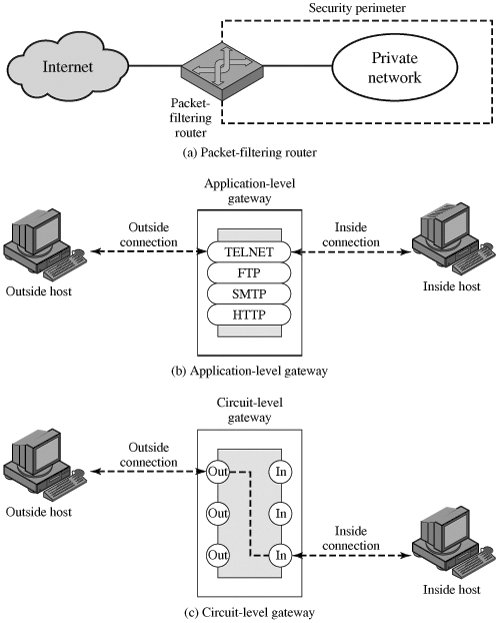
Packet-Filtering Router A packet-filtering router applies a set of rules to each incoming and outgoing IP packet and then forwards or discards the packet. The router is typically configured to filter packets going in both directions (from and to the internal network). Filtering rules are based on information contained in a network packet: Source IP address: The IP address of the system that originated the IP packet (e.g., 192.178.1.1) Destination IP address: The IP address of the system the IP packet is trying to reach (e.g., 192.168.1.2) Source and destination transport-level address: The transport level (e.g., TCP or UDP) port number, which defines applications such as SNMP or TELNET
[Page 626]IP protocol field: Defines the transport protocol Interface: For a router with three or more ports, which interface of the router the packet came from or which interface of the router the packet is destined for
The packet filter is typically set up as a list of rules based on matches to fields in the IP or TCP header. If there is a match to one of the rules, that rule is invoked to determine whether to forward or discard the packet. If there is no match to any rule, then a default action is taken. Two default policies are possible: The default discard policy is more conservative. Initially, everything is blocked, and services must be added on a case-by-case basis. This policy is more visible to users, who are more likely to see the firewall as a hindrance. The default forward policy increases ease of use for end users but provides reduced security; the security administrator must, in essence, react to each new security threat as it becomes known. Table 20.1, from [BELL94b], gives some examples of packet-filtering rule sets. In each set, the rules are applied top to bottom. The "*" in a field is a wildcard designator that matches everything. We assume that the default = discard policy is in force. Table 20.1. Packet-Filtering Examples (This item is displayed on page 627 in the print version) A | action | ourhost | port | theirhost | port | comment | block | * | * | SPIGOT | * | we don't trust these people | allow | OUR-GW | 25 | * | * | connection to our SMTP port | B | action | ourhost | port | theirhost | port | comment | block | * | * | * | * | default | C | action | ourhost | port | theirhost | port | comment | allow | * | * | * | 25 | connection to their SMTP port | D | action | src | port | dest | port | flags | comment | allow | {our hosts} | * | * | 25 | | our packets to their SMTP port | allow | * | 25 | * | * | ACK | their replies | E | action | src | port | dest | port | flags | comment | allow | {our hosts} | * | * | * | | our outgoing calls | allow | * | * | * | * | ACK | replies to our calls | allow | * | * | * | >1024 | | traffic to nonservers |
Inbound mail is allowed (port 25 is for SMTP incoming), but only to a gateway host. However, packets from a particular external host, SPIGOT, are blocked because that host has a history of sending massive files in e-mail messages. This is an explicit statement of the default policy. All rule sets include this rule implicitly as the last rule. This rule set is intended to specify that any inside host can send mail to the outside. A TCP packet with a destination port of 25 is routed to the SMTP server on the destination machine. The problem with this rule is that the use of port 25 for SMTP receipt is only a default; an outside machine could be configured to have some other application linked to port 25. As this rule is written, an attacker could gain access to internal machines by sending packets with a TCP source port number of 25. This rule set achieves the intended result that was not achieved in C. The rules take advantage of a feature of TCP connections. Once a connection is set up, the ACK flag of a TCP segment is set to acknowledge segments sent from the other side. Thus, this rule set states that it allows IP packets where the source IP address is one of a list of designated internal hosts and the destination TCP port number is 25. It also allows incoming packets with a source port number of 25 that include the ACK flag in the TCP segment. Note that we explicitly designate source and destination systems to define these rules explicitly. This rule set is one approach to handling FTP connections. With FTP, two TCP connections are used: a control connection to set up the file transfer and a data connection for the actual file transfer. The data connection uses a different port number that is dynamically assigned for the transfer. Most servers, and hence most attack targets, live on low-numbered ports; most outgoing calls tend to use a higher-numbered port, typically above 1023. Thus, this rule set allows
[Page 628]Packets that originate internally Reply packets to a connection initiated by an internal machine Packets destined for a high-numbered port on an internal machine This scheme requires that the systems be configured so that only the appropriate port numbers are in use.
Rule set E points out the difficulty in dealing with applications at the packet-filtering level. Another way to deal with FTP and similar applications is an application-level gateway, described later in this section. One advantage of a packet-filtering router is its simplicity. Also, packet filters typically are transparent to users and are very fast. [WACK02] lists the following weaknesses of packet filter firewalls: Because packet filter firewalls do not examine upper-layer data, they cannot prevent attacks that employ application-specific vulnerabilities or functions. For example, a packet filter firewall cannot block specific application commands; if a packet filter firewall allows a given application, all functions available within that application will be permitted. Because of the limited information available to the firewall, the logging functionality present in packet filter firewalls is limited. Packet filter logs normally contain the same information used to make access control decisions (source address, destination address, and traffic type). Most packet filter firewalls do not support advanced user authentication schemes. Once again, this limitation is mostly due to the lack of upper-layer functionality by the firewall. They are generally vulnerable to attacks and exploits that take advantage of problems within the TCP/IP specification and protocol stack, such as network layer address spoofing. Many packet filter firewalls cannot detect a network packet in which the OSI Layer 3 addressing information has been altered. Spoofing attacks are generally employed by intruders to bypass the security controls implemented in a firewall platform. Finally, due to the small number of variables used in access control decisions, packet filter firewalls are susceptible to security breaches caused by improper configurations. In other words, it is easy to accidentally configure a packet filter firewall to allow traffic types, sources, and destinations that should be denied based on an organization's information security policy.
Some of the attacks that can be made on packet-filtering routers and the appropriate countermeasures are the following: IP address spoofing: The intruder transmits packets from the outside with a source IP address field containing an address of an internal host. The attacker hopes that the use of a spoofed address will allow penetration of systems that employ simple source address security, in which packets from specific trusted internal hosts are accepted. The countermeasure is to discard packets with an inside source address if the packet arrives on an external interface.
[Page 629]Source routing attacks: The source station specifies the route that a packet should take as it crosses the Internet, in the hopes that this will bypass security measures that do not analyze the source routing information. The countermeasure is to discard all packets that use this option. Tiny fragment attacks: The intruder uses the IP fragmentation option to create extremely small fragments and force the TCP header information into a separate packet fragment. This attack is designed to circumvent filtering rules that depend on TCP header information. Typically, a packet filter will make a filtering decision on the first fragment of a packet. All subsequent fragments of that packet are filtered out solely on the basis that they are part of the packet whose first fragment was rejected. The attacker hopes that the filtering router examines only the first fragment and that the remaining fragments are passed through. A tiny fragment attack can be defeated by enforcing a rule that the first fragment of a packet must contain a predefined minimum amount of the transport header. If the first fragment is rejected, the filter can remember the packet and discard all subsequent fragments.
Stateful Inspection Firewalls A traditional packet filter makes filtering decisions on an individual packet basis and does not take into consideration any higher layer context. To understand what is meant by context and why a traditional packet filter is limited with regard to context, a little background is needed. Most standardized applications that run on top of TCP follow a client/server model. For example, for the Simple Mail Transfer Protocol (SMTP), e-mail is transmitted from a client system to a server system. The client system generates new e-mail messages, typically from user input. The server system accepts incoming e-mail messages and places them in the appropriate user mailboxes. SMTP operates by setting up a TCP connection between client and server, in which the TCP server port number, which identifies the SMTP server application, is 25. The TCP port number for the SMTP client is a number between 1024 and 65535 that is generated by the SMTP client. In general, when an application that uses TCP creates a session with a remote host, it creates a TCP connection in which the TCP port number for the remote (server) application is a number less than 1024 and the TCP port number for the local (client) application is a number between 1024 and 65535. The numbers less than 1024 are the "well-known" port numbers and are assigned permanently to particular applications (e.g., 25 for server SMTP). The numbers between 1024 and 65535 are generated dynamically and have temporary significance only for the lifetime of a TCP connection. A simple packet-filtering firewall must permit inbound network traffic on all these high-numbered ports for TCP-based traffic to occur. This creates a vulnerability that can be exploited by unauthorized users. A stateful inspection packet filter tightens up the rules for TCP traffic by creating a directory of outbound TCP connections, as shown in Table 20.2. There is an entry for each currently established connection. The packet filter will now allow incoming traffic to high-numbered ports only for those packets that fit the profile of one of the entries in this directory. Table 20.2. Example Stateful Firewall Connection State Table [WACK02] (This item is displayed on page 630 in the print version) Source Address | Source Port | Destination Address | Destination Port | Connection State |
|---|
192.168.1.100 | 1030 | 210.9.88.29 | 80 | Established | 192.168.1.102 | 1031 | 216.32.42.123 | 80 | Established | 192.168.1.101 | 1033 | 173.66.32.122 | 25 | Established | 192.168.1.106 | 1035 | 177.231.32.12 | 79 | Established | 223.43.21.231 | 1990 | 192.168.1.6 | 80 | Established | 219.22.123.32 | 2112 | 192.168.1.6 | 80 | Established | 210.99.212.18 | 3321 | 192.168.1.6 | 80 | Established | 24.102.32.23 | 1025 | 192.168.1.6 | 80 | Established | 223.212.212 | 1046 | 192.168.1.6 | 80 | Established |
Application-Level Gateway An application-level gateway, also called a proxy server, acts as a relay of application-level traffic (Figure 20.1b). The user contacts the gateway using a TCP/IP application, such as Telnet or FTP, and the gateway asks the user for the name of the remote host to be accessed. When the user responds and provides a valid user ID and authentication information, the gateway contacts the application on the remote host and relays TCP segments containing the application data between the two endpoints. If the gateway does not implement the proxy code for a specific application, the service is not supported and cannot be forwarded across the firewall. Further, the gateway can be configured to support only specific features of an application that the network administrator considers acceptable while denying all other features.
[Page 630] Application-level gateways tend to be more secure than packet filters. Rather than trying to deal with the numerous possible combinations that are to be allowed and forbidden at the TCP and IP level, the application-level gateway need only scrutinize a few allowable applications. In addition, it is easy to log and audit all incoming traffic at the application level. A prime disadvantage of this type of gateway is the additional processing overhead on each connection. In effect, there are two spliced connections between the end users, with the gateway at the splice point, and the gateway must examine and forward all traffic in both directions. Circuit-Level Gateway A third type of firewall is the circuit-level gateway (Figure 20.1c). This can be a stand-alone system or it can be a specialized function performed by an application-level gateway for certain applications. A circuit-level gateway does not permit an end-to-end TCP connection; rather, the gateway sets up two TCP connections, one between itself and a TCP user on an inner host and one between itself and a TCP user on an outside host. Once the two connections are established, the gateway typically relays TCP segments from one connection to the other without examining the contents. The security function consists of determining which connections will be allowed. A typical use of circuit-level gateways is a situation in which the system administrator trusts the internal users. The gateway can be configured to support application-level or proxy service on inbound connections and circuit-level functions for outbound connections. In this configuration, the gateway can incur the processing overhead of examining incoming application data for forbidden functions but does not incur that overhead on outgoing data.
[Page 631] An example of a circuit-level gateway implementation is the SOCKS package [KOBL92]; version 5 of SOCKS is defined in RFC 1928. The RFC defines SOCKS in the following fashion: The protocol described here is designed to provide a framework for client-server applications in both the TCP and UDP domains to conveniently and securely use the services of a network firewall. The protocol is conceptually a "shim-layer" between the application layer and the transport layer, and as such does not provide network-layer gateway services, such as forwarding of ICMP messages. SOCKS consists of the following components: The SOCKS server, which runs on a UNIX-based firewall. The SOCKS client library, which runs on internal hosts protected by the firewall. SOCKS-ified versions of several standard client programs such as FTP and TELNET. The implementation of the SOCKS protocol typically involves the recompilation or relinking of TCP-based client applications to use the appropriate encapsulation routines in the SOCKS library.
When a TCP-based client wishes to establish a connection to an object that is reachable only via a firewall (such determination is left up to the implementation), it must open a TCP connection to the appropriate SOCKS port on the SOCKS server system. The SOCKS service is located on TCP port 1080. If the connection request succeeds, the client enters a negotiation for the authentication method to be used, authenticates with the chosen method, and then sends a relay request. The SOCKS server evaluates the request and either establishes the appropriate connection or denies it. UDP exchanges are handled in a similar fashion. In essence, a TCP connection is opened to authenticate a user to send and receive UDP segments, and the UDP segments are forwarded as long as the TCP connection is open. Bastion Host A bastion host is a system identified by the firewall administrator as a critical strong point in the network's security. Typically, the bastion host serves as a platform for an application-level or circuit-level gateway. Common characteristics of a bastion host include the following: The bastion host hardware platform executes a secure version of its operating system, making it a trusted system. Only the services that the network administrator considers essential are installed on the bastion host. These include proxy applications such as Telnet, DNS, FTP, SMTP, and user authentication. The bastion host may require additional authentication before a user is allowed access to the proxy services. In addition, each proxy service may require its own authentication before granting user access. Each proxy is configured to support only a subset of the standard application's command set.
[Page 632]Each proxy is configured to allow access only to specific host systems. This means that the limited command/feature set may be applied only to a subset of systems on the protected network. Each proxy maintains detailed audit information by logging all traffic, each connection, and the duration of each connection. The audit log is an essential tool for discovering and terminating intruder attacks. Each proxy module is a very small software package specifically designed for network security. Because of its relative simplicity, it is easier to check such modules for security flaws. For example, a typical UNIX mail application may contain over 20,000 lines of code, while a mail proxy may contain fewer than 1000. Each proxy is independent of other proxies on the bastion host. If there is a problem with the operation of any proxy, or if a future vulnerability is discovered, it can be uninstalled without affecting the operation of the other proxy applications. Also, if the user population requires support for a new service, the network administrator can easily install the required proxy on the bastion host. A proxy generally performs no disk access other than to read its initial configuration file. This makes it difficult for an intruder to install Trojan horse sniffers or other dangerous files on the bastion host. Each proxy runs as a nonprivileged user in a private and secured directory on the bastion host.
Firewall Configurations In addition to the use of a simple configuration consisting of a single system, such as a single packet-filtering router or a single gateway (Figure 20.1), more complex configurations are possible and indeed more common. Figure 20.2 illustrates three common firewall configurations. We examine each of these in turn. Figure 20.2. Firewall Configurations (This item is displayed on page 633 in the print version) 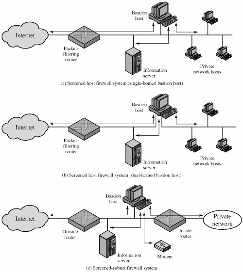
In the screened host firewall, single-homed bastion configuration (Figure 20.2a), the firewall consists of two systems: a packet-filtering router and a bastion host. Typically, the router is configured so that For traffic from the Internet, only IP packets destined for the bastion host are allowed in. For traffic from the internal network, only IP packets from the bastion host are allowed out.
The bastion host performs authentication and proxy functions. This configuration has greater security than simply a packet-filtering router or an application-level gateway alone, for two reasons. First, this configuration implements both packet-level and application-level filtering, allowing for considerable flexibility in defining security policy. Second, an intruder must generally penetrate two separate systems before the security of the internal network is compromised. This configuration also affords flexibility in providing direct Internet access. For example, the internal network may include a public information server, such as a Web server, for which a high level of security is not required. In that case, the router can be configured to allow direct traffic between the information server and the Internet.
[Page 633]In the single-homed configuration just described, if the packet-filtering router is completely compromised, traffic could flow directly through the router between the Internet and other hosts on the private network. The screened host firewall, dual-homed bastion configuration physically prevents such a security breach (Figure 20.2b). The advantages of dual layers of security that were present in the previous configuration are present here as well. Again, an information server or other hosts can be allowed direct communication with the router if this is in accord with the security policy.
[Page 634]The screened subnet firewall configuration of Figure 20.2c is the most secure of those we have considered. In this configuration, two packet-filtering routers are used, one between the bastion host and the Internet and one between the bastion host and the internal network. This configuration creates an isolated subnetwork, which may consist of simply the bastion host but may also include one or more information servers and modems for dial-in capability. Typically, both the Internet and the internal network have access to hosts on the screened subnet, but traffic across the screened subnet is blocked. This configuration offers several advantages: There are now three levels of defense to thwart intruders. The outside router advertises only the existence of the screened subnet to the Internet; therefore, the internal network is invisible to the Internet. Similarly, the inside router advertises only the existence of the screened subnet to the internal network; therefore, the systems on the inside network cannot construct direct routes to the Internet.
|