Working Inside Your PC
| < Day Day Up > |
| If you've never opened up a computer before, it can be pretty overwhelming. In this section, I'm going to help you get started with practical advice on how to
Opening the Case of a Desktop PCI recommend that you look at your system manual for case-opening instructions, particularly if you have a retail-store system made by HP or Compaq. Depending upon the type of case you have, you might need to remove just one or two screws , or maybe a handful. If you're opening the case to gain access to the motherboard, you might need to do more than just take the cover off the system. So-called "white box" systems are usually pretty straightforward to open, because they use case designs made for user access instead of low cost. Figure 2.18 shows the rear of two typical cases used by white-box computer dealers or as replacement cases. The computer on the left has a single screw holding the covers in place. After this screw is removed, the top panel must be removed before the side panels can be removed. The computer on the right uses four screws per side to hold the side panels in place, but the side panels can be removed without removing the top cover. The right-side panel can even be swung out and latched back into place for faster card and drive installation. Figure 2.18. Two generic cases compared to each other. Retail-store systems often use a single-piece molding that slips off the rear of the chassis. It can be held in place by several screws. Taking ESD PrecautionsAfter you open your PC, what should you do next ? caution
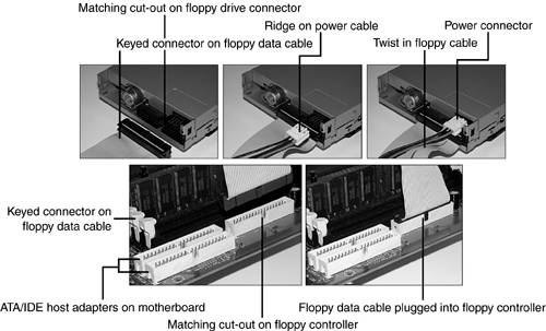
Ideally, you should wear a commercial wrist strap made for ESD protection and clip it to an unpainted metal part on the computer you are servicing , as in Figure 2.19, before you touch any other part of the interior of your computer. Figure 2.19. A wrist strap and some suitable places to clip it inside the system. When you put the wrist strap on, make sure the metal plate on the inside of the strap touches bare skin; don't wear it over a shirt or sweater, and make sure it's comfortably snug. When the wrist strap is connected to a metal part of the chassis with the alligator clip on the end of the cable that snaps onto the wrist strap, it equalizes the electrical potential of your body and the computer to prevent ESD discharge. However, if you don't have a wrist strap, touch unpainted metal on the chassis or the power supply before you touch or remove any cables or other parts . If possible, keep touching the chassis or power supply while you work. For more details on ESD protection, see Chapter 13, "Safety and Recycling." Connecting Internal and External Data CablesConnecting internal and external drives and devices is critical if you want to have reliably working PCs. Here are a couple of examples of how to do it right: Attaching Cables to the Floppy Drive and ControllerThe floppy drive uses a 34-pin cable that has a twist at one end. This end of the cable connects to the floppy drive (A: drive). The middle connector is used for the B: drive (if present; not supported on some machines). The connector with the untwisted end plugs into the floppy controller on the motherboard. The colored marking on the cable and the twist indicate the pin 1 side of the cable. This is important to note because floppy drives and controllers are not always keyed to prevent incorrect installation. The floppy drive is powered by a small 4-pin power cable. There is a small cut-out in the center of the connector on the drive that corresponds to a projection on the cable. Figure 2.20 shows how the floppy drive cable and power cable connect to the rear of a typical floppy drive and to the floppy controller. Figure 2.20. Connecting data and power cables to a typical 3.5-inch floppy drive (top) and floppy controller on motherboard (bottom). To install the cables
caution
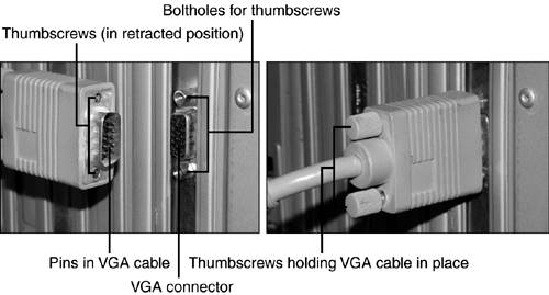
The installation of an ATA/IDE hard disk or other drive type is similar in many ways, but the cables used are different and the drives must be correctly jumpered. For more information on floppy drives and hard drives, cables, and floppy media, see Chapter 14. Attaching the VGA Cable to a Video Card or PortThe VGA cable has as many as 15 wires that are routed into a connector the same size as a serial (COM) port. Consequently, it is one of the heaviest cables you need to connect to a PC. If you don't attach it correctly, you could have poor-quality images on your monitor, and if the cable falls off, you won't have any picture at all. Depending upon the computer, the VGA port might be located on a card built into an expansion slot, or might be clustered with other ports at the rear of the computer. In either case, the port and the cable are the same. Figure 2.21 shows how the VGA cable should be connected to the VGA port. Figure 2.21. Connecting a VGA cable to a VGA port. To connect the VGA cable to the VGA port
For more information about graphics cards and cables, including installing and configuring cards that support multiple displays, see Chapter 9, "Video." Installing a PCI CardMost systems have at least one open PCI card slot; it's the standard card type used for most devices. If you need to add an internal modem, a network adapter, a USB 2.0, an IEEE-1394a, a hard disk, or a SCSI host adapter to a desktop PC, you will add a PCI card that includes the necessary port. Figure 2.22 shows the process of adding a PCI card ( specifically , a Serial ATA hard disk host adapter) to a typical system. The procedure for installing an AGP-based video card is similar, except that the AGP slot is used. Figure 2.22. Installing a Serial ATA card into a PCI slot. To add a PCI card
For more information about installing cards and configuring them, see Chapter 8, "Input/Output Devices and Cables"; Chapter 9, "Video"; Chapter 14, "Storage"; Chapter 19, "Installing and Configuring Hardware in Windows"; and Chapter 21, "Networking and Internet Connectivity." |

| < Day Day Up > |
EAN: N/A
Pages: 310