Simulating Wide-Area Network Connections
| < Free Open Study > |
| The other major part of modeling the internetwork consists of WAN connections. At this point in the design, you are concerned only with ISO Layer 1. You will continue to model the internetwork from Layer 1 on up because this is the most logical way to build any network. First, you will build all the physical connections to all your devices, and then you will configure all LAN interfaces, WAN interfaces, and finally your different networks together with routing protocols. Constructing a network in a layered approach allows for future growth and adaptation by upgrading or replacing a single layer at a time, while leaving the remaining layers unchanged. With this in mind, we will focus on physical aspects, such as cable types and pinouts. Part III, "Connecting LANs with Wide Area Networks (WANs)," focuses on ISO Layer 2 protocols. You can model WAN connections in three primary ways, and you can simulate a WAN in one way in a Cisco environment:
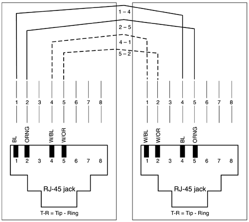
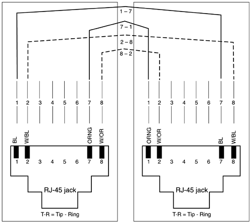
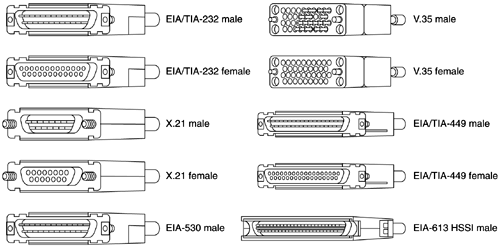
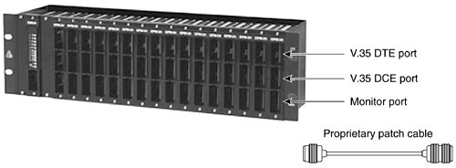
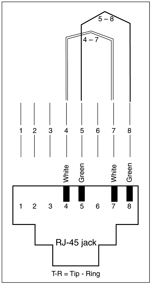
NOTE Of course, no book on networking would be complete without mentioning the OSI model; Appendix B, "The 'Abridged' OSI Reference Model," presents a brief overview of the OSI model. Modeling WANs by Using Special Crossover Cable Routers with Built-In or External CSU/DSUsTwo routers with built-in or external CSU/DSUs can be connected in a "back-to-back" mode. This functions as the Layer 1 for many WAN protocols, including PPP, HDLC, and others. This is done by utilizing a special crossover cable made from pinning out specific pins of a four-pair Category 5 cable. It is important to note that the crossover cable needed differs slightly from a T1 to a 56-kbps DSU. You must connect a router with a T1 service unit or CSU/DSU to another router with a T1 service unit or CSU/DSU. The same is true for a 56-kbps service unit. Figures 1-3 and 1-4 illustrate what pinouts you need to make a crossover cable, from a Category 5 cable for a T1 CSU/DSU and a 56-kbps CSU/DSU. Figure 1-3. Pinouts for a Crossover Cable for T1 Service Module or CSU/DSU Figure 1-4. Pinouts for a Crossover Cable for 56-kbps Service Module or CSU/DSU Modeling WANs by Using a V.35 DTE Cable to a V.35 DCE CableThe most common way to provide Layer 1 connectivity between routers is to connect a female V.35 DCE cable to a male V.35 DTE cable. The key factor in any back-to-back configuration is ensuring that one side of the link sets clocking. This is always the DCE side of the link. To configure the clock rate for an interface, simply add the command clock rate [ value ]. Example 1-3 demonstrates how to set the clocking on a serial interface to 64,000 bps. Example 1-3 Configuring the Clockrate on a DCE Interfaceframe_relay_switch(config)# int serial 5 frame_relay_switch(config-if)# clockrate 64000 frame_relay_switch(config-if)# ^Z frame_relay_switch# It is important to ensure that the cable is truly a V.35 DTE cable connecting to a V.35 DCE cable. The sex of the DCE or DTE cable is not relevant; however, you must connect a DCE side to a DTE side, and set the clock rate, as demonstrated in Example 1-3. Figure 1-5 illustrates many of the standard Cisco cable connectors, ranging from the common V.35 and RS-232 interfaces to EIA613-HSSI interfaces. Figure 1-5. Common Cable Interfaces for Cisco Routers These cables can be ordered from Cisco Systems, part number CAB-V35MT for the V.35 male DTE cable, and CAB-V35FC for the female DCE cable. Several companies also make serial and crossover cables at reasonable prices. At times when the cables are connected in a back-to-back mode, it might be hard to tell which one is the DCE cable. You might be in the field or working remotely, and you might not have physical access to your lab ”how, then, can you tell which cable is the DCE cable? The show controller command shows the cable type and shows whether the cable is DCE or DTE. Example 1-4 shows two interfaces on a Cisco 2501 router. Using the show controller command, you can tell what the interface type is. Example 1-4 Example of the show controllers CommandRouter# show controller serial 0 HD unit 0, idb = 0xCED94, driver structure at 0xD3B18 buffer size 1524 HD unit 0, V.35 DTE cable cpb = 0xE2, eda = 0x4140, cda = 0x4000 RX ring with 16 entries at 0xE24000 00 bd_ptr=0x4000 pak=0x0D66F0 ds=0xE2DDB0 status=80 pak_size=0 ***text omitted*** Router# show controller serial 1 HD unit 1, idb = 0xD7788, driver structure at 0xDC508 buffer size 1524 HD unit 1, RS-232 DCE cable cpb = 0xE3, eda = 0x2140, cda = 0x2000 RX ring with 16 entries at 0xE32000 00 bd_ptr=0x2000 pak=0x0DF0E4 ds=0xE3C468 status=00 pak_size=0 ***text omitted*** Interface Serial 0 is a V.35 DTE cable, and interface Serial 1 is an RS-232 DCE cable. Other serial cables, such as RS-232, are used for back-to-back connections, as long as a DCE cable is connected to DTE cable. It is important to note that each different cable type has certain speed restrictions. For example, it is not possible to simulate T1 speeds on RS-232 cables. For the most flexibility in lab environments, use V.35 cables whenever possible. Sometimes, you might want to switch your lab environment rather rapidly . You might want a serial connection attached to one router one day, whereas the next day you might want that same connection to go to another router. In these situations, it is best to use a patch panel of some sort . A V.35 patch panel is a common sight at large labs. The V.35 patch panel is simple to work with. Most V.35 patch panels have a female DTE port located on top, in the rear, and a V.35 male DCE port located in the middle, in the rear. The routers plug into these ports, the DTE cable to the DTE port, and the DCE cable to the DCE port. On the front of the patch panel are small patch ports, with one port in front of each DTE and DCE port. A black patch cable then enables you to patch one DTE port to one DCE port, thereby connecting one router to another router. To change the configuration, simply move the patch cable to another patch port. Using a patch panel in this manner allows for quick and rapid physical configuration of many serial links. Patch panels should be labeled on the front to designate which is the DCE and DTE port ”this can be key when troubleshooting physical layer issues. Figure 1-6 illustrates a V.35 Patch panel. Figure 1-6. V.35 Patch Panels Most patch panels also have a bottom port, right below the DCE port. This port is used for attaching a line monitor or data scope. Simulating WANs by Using HDLC and Loopback Plugs on CSU/DSUsYet another way to use WAN interfaces in your model is to deploy loopback plugs on your CSU/DSUs combined with running HDLC protocol. In addition, by putting a Layer 3 address, such as an IP or IPX address, on the interface, the interface will respond to ping s and will show up in routing tables. The Layer 2 encapsulation must also be set to HDLC when using loopback plugs. Routers with built-in CSU/DSUs or WAN interface cards (WICs), and even on routers with external CSU/DSUs, can have a loopback plug installed into the RJ-45 jack, thus spoofing the WAN interface as up. Example 1-5 illustrates output from the show interface command on a Cisco 2524, with a T1 WIC and a loopback plug installed. Example 1-5 The show interface Command of a Cisco 2524 with a T1 Loopback Plug Installed in Its WIC router# show interfaces serial 1 Serial1 is up, line protocol is up (looped) Hardware is HD64570 with FT1 CSU/DSU MTU 1500 bytes, BW 1544 Kbit, DLY 20000 usec, rely 255/255, load 1/255 Encapsulation HDLC, loopback not set, keepalive set (10 sec) Last input 00:00:02, output 00:00:02, output hang never Last clearing of "show interface" counters never Input queue: 0/75/0 (size/max/drops); Total output drops: 0 Queueing strategy: weighted fair Output queue: 0/1000/64/0 (size/max total/threshold/drops) Conversations 0/1/256 (active/max active/max total) Reserved Conversations 0/0 (allocated/max allocated) 5 minute input rate 0 bits/sec, 0 packets/sec 5 minute output rate 0 bits/sec, 0 packets/sec 2537 packets input, 148733 bytes, 0 no buffer Received 2537 broadcasts, 0 runts, 0 giants, 0 throttles 0 input errors, 0 CRC, 0 frame, 0 overrun, 0 ignored, 0 abort 2537 packets output, 148733 bytes, 0 underruns 0 output errors, 0 collisions, 1 interface resets 0 output buffer failures, 0 output buffers swapped out 1 carrier transitions DCD=up DSR=up DTR=up RTS=up CTS=up router# NOTE Loopback plugs can be useful in the field. Whenever a CSU/DSU or WIC is suspected to be malfunctioning, installing a loopback plug can quickly test the physical layer to the CSU/DSU. When the loopback plug is installed, the show interface command should show the interface as line up, protocol up and (looped). A loopback plug can be easy to make. You can use a simple cable kit to construct these plugs, or you can order them from most cable vendors , if they are supplied with the diagrams in Figures 1-7 and 1-8. Figure 1-7 demonstrates the pinouts required for an RJ-45 56-kbps loopback plug, while Figure 1-8 illustrates the pinouts required for an RJ-45 T1 or 1.544-Mbps loopback plug. Figure 1-7. Pinouts for an RJ-45 56-kbps Loopback Plug Figure 1-8. Pinouts for an RJ-45 T1 Loopback Plug Modeling WANs by Using a Cisco Router as a Frame Relay or X.25 SwitchThe third way to model a WAN is to configure a Cisco router as a Frame Relay or an X.25 switch. Any Cisco router with Cisco IOS Software Release 11.0 or later and at least two serial interfaces can be configured as an actual Frame Relay or X.25 switch. When configured as a Frame Relay switch, the router actually sends and receives the Frame Relay Local Management Interface (LMI), and it can even be configured to use Network-to-Network Interface (NNI), the standard interface between Frame Relay switches. Two interfaces are always needed because the switch is primarily a DCE device and requires two routers to serve as the DTE devices. Because the Frame Relay switch is a DCE-only device, it requires DCE serial cables as well. The Cisco 2522 and the 2523 series routers can perform the function of a Frame Relay switch with ample ports for many end devices. The Cisco 2522 provides two high-speed synchronous serial ports and eight low-speed asynchronous/synchronous serial ports. This router also has one Ethernet port in an RJ-45 or AUI configuration, and one ISDN BRI U interface in an RJ-45 configuration. The Cisco 2523 is exactly the same as the 2522, but instead of the Ethernet port, it has an RJ-45 Token Ring interface. Any Cisco router with multiple serial interfaces is a good choice for a Frame Relay or X.25 switch. The Frame Relay switching functions run independently of normal router functions, such as IP routing. Thus, this router can be used not only as a Frame Relay switch, but also as another routed device or a route generator. The detailed software configuration of a Frame Relay switch is covered later in this chapter, in the section "Configuring a Frame Relay Switch." TIP During the course of your studies and career in networking, you will come across many terms and acronyms. Sometimes, it can become difficult to remember all the rules, such as a DCE side requires a clock. One method of memorization that I use is word association. For example, I know that there are DCE and DTE sides to a cable. The C is the difference between the two, and C stands for "clock." Thus, the D C E side is the side on which you configure the clock signal. At this point, you might be wondering, "What about ATM? That's a LAN and WAN protocol ”where does that fit in?" Asynchronous Transfer Mode (ATM) was originally called the "duck" of networking because it was like a duck in a metaphorical sense. A duck can swim, fly, and walk. It doesn't walk that well and swims okay, but it flies really fast. ATM can do voice, data, and video, although it does some of them better then others. I had the same classification problems in deciding where to talk about ATM. Because ATM is a LAN and WAN technology and is highly specialized, it is covered in Chapter 8, "WAN Protocols and Technologies: Asynchronous Transfer Mode (ATM)." |
| < Free Open Study > |
EAN: 2147483647
Pages: 283
