Lab 27: DLSw TCP, LLC2, Promiscuous, Dynamic, and Backup Peer Configuration-Part II
| < Free Open Study > |
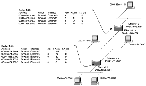
Transparent BridgingTransparent bridging is used to transport nonroutable protocols across Ethernet networks. Transparent bridges first were developed by DEC in the early 1980s. DEC submitted the work to the IEEE, which incorporated it into the IEEE 802.1 standard. The basic function of a bridge is to forward data across the network. The bridge accepts frames , briefly examines them, and then makes a forwarding decision based on the information in that frame. The bridge accomplishes this by building a bridge or station table. Figure 13-1 illustrates the bridge table in a bridged network. Figure 13-1. A Bridged Network Bridges operate at the first two layers of the OSI model. Recall from Chapter 2, "LAN Protocols: Configuring Catalyst Ethernet and Token Ring Switches," that the data link layer, Layer 2, is subdivided into two layers , the MAC and LLC. Bridges primarily operate at the MAC layer, working with source and destination MAC addresses. Transparent Bridging OperationBasically, a bridge operates in the following manner:
Spanning Tree ReviewBecause bridges use the process of flooding frames from segment to segment, they need a way to control loops . Three types of loop-prevention mechanisms are available on Cisco routers:
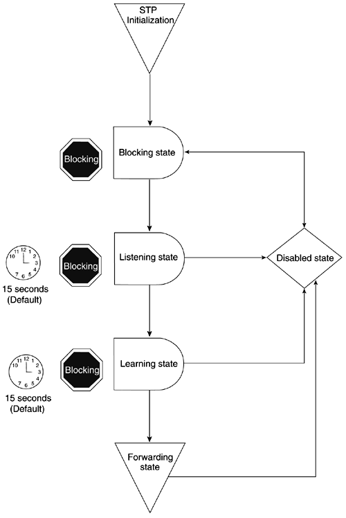
All forms of STP are similar, so we will focus on the primary one in use and the one used as the default for Cisco switches802.1d. The following information is reprinted from Chapter 2 that STP transitions through the phases illustrated by Figure 13-2 and explained in the sections that follow. Figure 13-2. The STP Transition Disabled StateThis state appears when a bridge having problems processes Bridged Protocol Data Units (BPDUs), when a trunk is improperly configured, or when the port is administratively down. Listening StateWhen a bridge port initializes, or in the absence of BPDUs for a certain amount of time, STP transitions to the listening state. When STP is in this state, the port is actually "blocking," and no user data is sent on the link. STP follows a four-step process for convergence:
Learning StatePorts that remain designated or root ports for a period of 15 seconds, the default forward delay, enter the learning state. In the learning state, the bridge waits another 15 seconds while it builds its bridge table. Forwarding and Blocking StatesWhen the bridge reaches this phase, ports that do not serve a special purpose, such a root port or a designated port, are called nondesignated ports. All designated ports are put in forwarding state, while all nondesignated ports are put in a blocking state. In the blocking state, a bridge does not send any configuration BPDUs, but it still listens to them. A blocking port also does not forward any user data. STP TimersSTP has three basic timers that regulate and age BPDUs:
STP uses the hello timer to space BPDUs and has a keepalive mechanism. The hello timer always should prevent the MAX age value from being hit. When the MAX Age timer expires, it usually indicates a link failure. When this happens, the bridge re-enters the listening state. It takes approximately 50 seconds for STP to recover from a link failure; 20 seconds for the BPDU to age out, the MAX Age; 15 seconds for listening; and 15 seconds for the learning state. Configuring Transparent BridgingConfiguring transparent bridging is a simple three-step process:
The first step in setting up transparent bridging is to define a Spanning-Tree Protocol and assign it a bridge group number. You can choose either the IEEE 802.1D Spanning-Tree Protocol or the Digital or IBM versions. The IEEE 802.1D Spanning-Tree Protocol is the preferred way of running the bridge. Use the Digital Spanning-Tree Protocol or the IBM version only for backward compatibility. The next step is to assign each network interface to a bridge group. A bridge group is defined by Cisco as follows:
If you are configuring bridging over a Frame Relay multipoint network or DDR network, an additional map statement will be needed to carry the bridged traffic over the network. A couple of reasons exist for placing the interface into a bridge group:
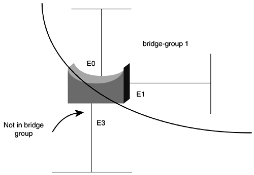
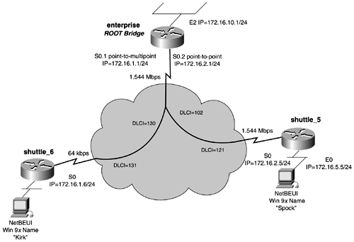
In Figure 13-3, interfaces e0 and e1 are in bridge group 1. These interfaces will forward bridged traffic to another. Interface e3 is not part of the bridge group and will not receive traffic from the bridge group. Figure 13-3. Transparent Bridging Bridge Groups TIP An effective way to isolate bridged traffic on switched networks is to create a VLAN just for bridged traffic. Any devices that require bridged traffic will exist on this VLAN. Data-link switching then can be used to take this VLAN traffic or bridged traffic across the LAN or WAN, without propagating its traffic to every segment in between. Transparent Bridging ModelFigure 13-4 presents a practical example of transparent bridging. In this model, the workstations are MS Windows 9 x running NetBEUI, a nonroutable protocol. For the workstations to communicate, transparent bridging must be enabled across the Frame Relay network and on the Ethernet interfaces of the routers shuttle_5 and shuttle_6. Figure 13-4. Transparent Bridging To enable transparent bridging on the enterprise router, follow the three-step process. Begin by assigning a bridge group and STP to the bridging domain. This is accomplished with the global router command bridge group 1 protocol ieee. In this model, you will be using 802.1d as the Spanning-Tree Protocol. The second step involves assigning interfaces to bridge groups. This is done with the interface command bridge-group 1. On the enterprise router, this command must be entered on the E0 interface, s0.1 and s0.2 Frame Relay interfaces. Because S0.1 is a Frame Relay multipoint, it also needs to have a frame-relay map bridge statement, mapping a specific DLCI to the bridge. Finally, the third step involves setting a root bridge. In this model, we have chosen the enterprise router to be the root for STP. To force root selection, we elected to use the global router command bridge-group 1 priority 100, setting the bridge priority of the enterprise router/bridge to be 100. Example 13-1 lists the configuration of the enterprise router. Example 13-1 Transparent Bridge Configuration on the enterprise Routerhostname enterprise ! <<<text omitted>>> ! interface Ethernet2 ip address 172.16.10.1 255.255.255.0 no ip directed-broadcast media-type 10BaseT bridge-group 1 The configurations of the shuttle_5 and shuttle_6 routers resemble the enterprise router's configuration. Example 13-2 lists the bridging portions of the shuttle_5 and shuttle_6 routers, respectively. Note that the Frame Relay map statements are needed only on Frame Relay multipoint networks. Example 13-2 Transparent Bridge Configuration on the shuttle_5 and shuttle_6 Routershostname shuttle_5 ! interface Ethernet0 ip address 172.16.5.5 255.255.255.0 bridge-group 1 Verifying Transparent Bridging, the "Big show" for Transparent Bridging and STPCisco offers some useful commands that aid in verifying the operation of the bridging environment. I can't recommend using any of the debug commands for transparent bridging. The ones available are cryptic or offer little valuable informationfor example: 11:23:34: ST: Serial0.1 0000000000800000605CF35DA400000000800000605CF35DA4800600 00140002000F00 Instead of trying to break down the bit stream that debug spantree tree provides, use other commands that prove to be more useful and easier to understand. The big show commands are as follows: show bridge [ bridge_number ] show spanning-tree [ bridge_number] show bridge CommandThe show bridge command shows the current state of the bridge, the MAC addresses it has learned, and whether it is forwarding on specific interfaces. Age and transmit and receive counts are also listed. If the bridge number is appended to the command, it lists the known bridge ports and the STP state they are in: learning, listening, forwarding, or blocking. Example 13-3 demonstrates the versions of the show bridge command on the shuttle_5 router from the previous model. For a more detailed explanation of the STP states, see Chapter 2. Example 13-3 show bridge Command Output on the shuttle_5 Routershuttle_5# show bridge Total of 300 station blocks, 296 free Codes: P - permanent, S - self Bridge Group 1: Address Action Interface Age RX count TX count 0000.8139.6c45 forward Ethernet0 0 248 0 0000.863c.3b41 forward Serial0 0 126 107 00e0.b055.5789 forward Serial0 0 506 0 00a0.cc74.54a4 forward Ethernet0 0 449 157 shuttle_5# show bridge group Bridge Group 1 is running the IEEE compatible Spanning Tree protocol Port 2 (Ethernet0) of bridge group 1 is forwarding Port 6 (Serial0 Frame Relay) of bridge group 1 is forwarding show spanning-tree CommandThe show spanning-tree command for bridges provides nearly identical information as the show spanning-tree command found on the Catalyst switches. The relevant information that this command provides is the current root of the Spanning Tree, the cost to root, its priority, as well as detailed STP timer information. For more specific information on the fields listed and their meaning, review the section, "Chapter 2. Example 13-4 lists the output of the show spanning-tree command on the enterprise router from the previous model. Note that this bridge is root and has a priority of 100, just as configured in the model. Example 13-4 show spanning-tree Command on the enterprise Routerenterprise# show spanning-tree Bridge group 1 is executing the IEEE compatible Spanning Tree protocol Bridge Identifier has priority 100, address 00e0.1e58.e798 Configured hello time 2, max age 20, forward delay 15 We are the root of the spanning tree Topology change flag not set, detected flag not set Times: hold 1, topology change 35, notification 2 hello 2, max age 20, forward delay 15 Timers: hello 0, topology change 0, notification 0 bridge aging time 300 Port 8 (Ethernet2) of Bridge group 1 is forwarding Port path cost 100, Port priority 128 Designated root has priority 100, address 00e0.1e58.e798 Designated bridge has priority 100, address 00e0.1e58.e798 Designated port is 8, path cost 0 Timers: message age 0, forward delay 0, hold 0 BPDU: sent 876, received 0 Port 13 (Serial0.1 Frame Relay) of Bridge group 1 is forwarding Port path cost 647, Port priority 128 Designated root has priority 100, address 00e0.1e58.e798 Designated bridge has priority 100, address 00e0.1e58.e798 Designated port is 13, path cost 0 Timers: message age 0, forward delay 0, hold 0 BPDU: sent 632, received 2 Port 14 (Serial0.2 Frame Relay) of Bridge group 1 is forwarding Port path cost 647, Port priority 128 Designated root has priority 100, address 00e0.1e58.e798 Designated bridge has priority 100, address 00e0.1e58.e798 Designated port is 14, path cost 0 Timers: message age 0, forward delay 0, hold 0 BPDU: sent 347, received 0 enterprise# NOTE Various levels of Cisco IOS Software Release 12.0 have Spanning Tree disabled by default. To enable Spanning Tree, use the command no bridge-group bridge_number spanning-disabled. Verifying Transparent Bridging with Windows 9 x or 2000Windows 9 x or 2000 with Microsoft networking enabledor, more specifically , NetBEUI enabledprovides a great test application for all bridged and DLSw networks. To test any bridging type environments, use two Windows workstations with Microsoft networking and NetBEUI enabled. If you also enable Microsoft file and print sharing, you will be able to test file transfers across the bridged or DLSw network. Using the network browser or the Find Computer application in Windows, you can force broadcast data across the network. For more information on configuring Windows networking, see Chapter 1, "The Key Components for Modeling an Internetwork," or consult the Microsoft documentation. |
| < Free Open Study > |
EAN: 2147483647
Pages: 283