Lab 24: OSPF Multiple Area Routing, Authentication, Path Manipulation, Default Routing ”Part I Practical Scenario Throughout this text, we have stated that most networks today are connected to the Internet in some form. Connecting to the Internet usually requires a default route to be propagated throughout the network. The following lab gives you practice in configuring multiple OSPF areas and types, authenticating an area, manipulating paths, and propagating a default route throughout OSPF. Lab Exercise The famous Dr. Stai has a small group of regional offices. Each office specializes in a specific area of dentistry, such as root canals or fillings. Dr. Stai wants to connect the offices over a Frame Relay network. The offices also will share a common connection to the Internet so that they can have access to the latest techniques and new pain-reduction methods . Your task is to configure an OSPF network by using the following parameters as design guidelines: -
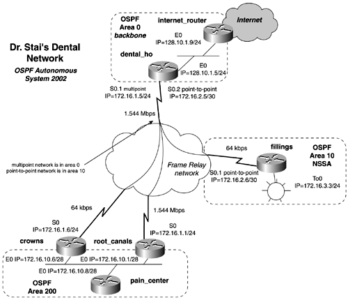
Configure an IP network, as depicted in Figure 12-14, by using OSPF as the routing protocol and 2002 as the Autonomous System ID. Figure 12-14. Dr. Stai's Dental Network  -
Configure the Frame Relay network as a point-to-point network between dental_ho and the router fillings. Use a Frame Relay multipoint network between the dental_ho, crowns, and root_canals routers. -
Configure all the OSPF areas as denoted in the diagram. Area 10 is to be configured as a NSSA area. -
Inject a default route into the dental_ho router pointing all Internet traffic toward the network 128.10.1.0/24. Propagate the default route within the OSPF domain. -
Configure Type 2 authentication in Area 200. -
The root_canals router has a T1 to the dental_ho router. Configure the network so that the pain_center router will use the T1 of root_canals over the crowns router's 64-kbps link when accessing any networks across the WAN. Lab Objectives -
Configure Dr. Stai's dental network as depicted in Figure 12-14. Configure IP as denoted in the figure, as well. The LAN topology type is not important in this lab. -
Use the Frame Relay data link protocol on the WAN. Use only multipoint networks and point-to-point networks, as indicated in the figure. -
Ensure full IP connectivity to all IP interfaces ”that is, be sure that you can ping all Frame Relay and LAN interfaces. -
Do not change the default OSPF network type. Do not use any static routes. -
Inject a default route into the dental_ho router. Direct all IP traffic toward the subnet 128.10.1.0/24. Use a default network to accomplish this. Propagate the default route within OSPF. -
Use Type 2 authentication on Area 200. Use cisco as the password. -
Tune OSPF so that the pain_center router will have a preferred path through the router root_canals router over the crowns router. That is, all traffic from the pain_center router should travel through the router root_canals. -
(Optional) Propagate the default route only if the subnet 128.10.1.0/24 is present in the route table of the dental_ho router. If this route is not present, the default route should not get propagated because the dental_ho router cannot reach it. Note: You will be able to control only the default route to normal areas in this lab, so do not worry about controlling it in the NSSA area. Equipment Needed -
Six Cisco routers. Four will be connected through V.35 back-to-back cables or in a similar manner to a Frame Relay switch. -
Three LAN segments, provided by hubs or switches. The LAN topology is not significant in this lab. The Internet connection and router can be real or not; this does not affect the configuration of the router. Physical Layout and Prestaging -
Connect the hubs and serial cables to the routers, as shown in Figure 12-14. -
Configure an additional router to serve as the connection to the Internet. This is totally optional. -
A Frame Relay switch with three PVCs also is required. Example 12-32 lists the Frame Relay configuration used in this lab. Example 12-32 Frame Relay Switch Configuration hostname frame_switch ! frame-relay switching ! <<<text omitted>>> ! interface Serial0 no ip address encapsulation frame-relay no fair-queue clockrate 148000 frame-relay intf-type dce frame-relay route 111 interface Serial1 110 frame-relay route 121 interface Serial3 102 frame-relay route 150 interface Serial5 151 ! interface Serial1 no ip address encapsulation frame-relay clockrate 148000 frame-relay intf-type dce frame-relay route 110 interface Serial0 111 ! interface Serial2 no ip address shutdown ! interface Serial3 no ip address encapsulation frame-relay clockrate 64000 frame-relay intf-type dce frame-relay route 102 interface Serial0 121 ! interface Serial5 no ip address encapsulation frame-relay clockrate 64000 frame-relay intf-type dce frame-relay route 151 interface Serial0 150 |
