Technical Overview of RIP
| < Free Open Study > |
Configuring RFC 2225 (Classical IP)Classical IP, specified in RFC 2225, is a dynamic method of IP interconnectivity through the ATM network. Classical IP uses RFC 2684 encapsulation. It provides a dynamic method for IP interconnectivity through the ATM network, freeing you from the necessity of configuring manually intensive mapping statements. Here is my definition of Classical IP:
Classical IP utilizes a client/server architecture, which helps the ATM cloud pretend that it is a broadcast domain. Recall that IP ARP is a local broadcast. Because ATM is a nonbroadcast domain, deployment of the client/server architecture solves the problem. All the clients connect to the server, and the server performs the ARP function. Notice that only SVC-based ATM networks deploy a client/server architecture. The PVC-based ATM networks do not require it. This is because PVC-based ATM networks have VCs pre-established and deploy locally significant ATM addressing. PVC-based ATM deploy InATMARP to resolve VCs identifiers to the corresponding IP addresses, without involvement of an ARP server. This is exactly how InARP Frame Relay operates as well. Please note that the original Classical IP specification, RFC 1577, does not specify ARP server redundancy. Cisco has had a proprietary solution to provide server redundancy prior to release of RFC 2225, which provisions for ARP server redundancy. For more information on the theoretical part of Classical IP, refer to the Cisco ATM Solutions book. Now let's look at the configuration examples for PVC- and SVC-based ATM networks. PVC ImplementationClassical IP implementation through the use of PVCs uses InATMARP, which dynamically announces to the edge devices the IP addresses that are associated with the predefined PVCs. As a result, the edge devices build a dynamic ARP table between their IP addresses and the corresponding PVCs' VCD numbers . Each router, A, B, C, and D, dynamically builds a table by using InATMARP. The table associates the IP addresses with the locally significant VCD numbers, as listed in Table 8-7. Table 8-7. Dynamic IP and VCD Number Assignment
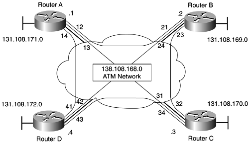
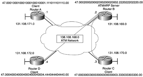
The syntax of PVC commands for Classical IP is identical to that of the regular PVC commands. You need to create PVCs as you would when implementing RFC 2684. Only two differences exist. You need to specify inarp at the end of the atm pvc command, and you have to omit the map- group statement that is referencing the corresponding map list. Table 8-4 provides all the details of the PVC command components . Let's examine the network illustrated in Figure 8-5. You have four routers interconnected across the ATM network. The identified VCD values enable a fully meshed topology, which results in a direct VC availability from any to any router. Figure 8-5. Classical IP over PVC-Based ATM Network Example 8-6 presents the configuration for all routers. Example 8-6 Classical IP Implementation Using PVC-Based ATM Network_______________________________________________________________________ Router A (config)# interface atm 0 no shutdown interface atm 0.1 ip address 138.108.168.1 255.255.255.0 atm pvc 12 0 77 aal5snap inarp 5 atm pvc 13 0 78 aal5snap inarp 5 atm pvc 14 0 79 aal5snap inarp 5 _______________________________________________________________________ Router B (config)# interface atm 0 no shutdown interface atm 0.1 ip address 138.108.168.2 255.255.255.0 atm pvc 21 0 87 aal5snap inarp 5 atm pvc 23 0 88 aal5snap inarp 5 atm pvc 24 0 89 aal5snap inarp 5 _______________________________________________________________________ Router C (config)# interface atm 0 no shutdown int atm 0.1 ip address 138.108.168.3 255.255.255.0 atm pvc 31 0 97 aal5snap inarp 5 atm pvc 32 0 98 aal5snap inarp 5 atm pvc 34 0 99 aal5snap inarp 5 _______________________________________________________________________ Router D (config)# interface atm 0 no shutdown int atm 0.1 ip address 138.108.168.4 255.255.255.0 atm pvc 41 0 107 aal5snap inarp 5 atm pvc 42 0 108 aal5snap inarp 5 atm pvc 43 0 109 aal5snap inarp 5 All the routers are configured to send Inverse ARP datagrams every 5 minutes. SVC ImplementationImplementing Classical IP over SVC-based ATM networks is based on a client/server architecture. This implies that there must be a server providing services to many clients. Classical IP provisions one ARP server, called ATMARP server, for many clients within a single broadcast domain. No longer do you have to configure static mapping between the globally significant ATM addresses and IP addresses ”the ATMARP server takes care of it dynamically. The simplicity of the architecture provides for little configuration in both ATMARP server and clients. All you have to do is assign either your full ATM address or the ESI prefix only (in this case, each router learns the prefix dynamically from an ingress ATM switch) in both clients and servers. Then, clients have to specify the full ATM address of the ATMARP server. All clients and a server must have the signaling and the ILMI PVCs. Then, the magic begins. Clients, knowing the ATMARP server address, automatically announce themselves to the server. In turn , when the client/server VC is set, the server builds the dynamic ARP table, containing the cross-reference between the clients' IP and ATM addresses. Figure 8-6 illustrates a sample Classical IP setup, where all four routers share one IP network, 138.108.168.0, across the ATM cloud. Router B is the ATMARP server, and routers A, C, and D are the clients. Figure 8-6. Classical IP over SVC-Based ATM Network After you define the clients, each one sets up a VC to the ATMARP server, Router B. Then, each client sends ATMARP request packets to the ATMARP server. The server, Router B, examines each ATMARP request packet and uses the information to build its ATMARP cache. This information is a dynamic cross-reference between the clients' ATM and IP addresses, as defined in Table 8-8. Using the ARP table entries, clients can communicate with each other without the need for static map list entries. Table 8-8. Dynamically Generated ATMARP Server Cache Entries
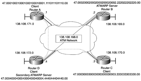
Example 8-7 depicts the configurations that are required in all four routers (routers A, C, and D are clients; Router B is the ATMARP server). Notice that static mapping no longer is required. Example 8-7 Classical IP Implementation Using ATM SVC-Based NetworkRouter A (config)# interface atm 0 atm pvc 1 0 5 qsaal no shutdown interface atm 0.1 ip address 138.10.168.1 255.255.255.0 atm nsap-address 47.000100010001000100010001.111011101110.00 atm arp-server nsap 47.000200020002000200020002.222022202220.00 _______________________________________________________________________ Router B (config)# interface atm 0 atm pvc 1 0 5 qsaal no shutdown interface atm 0.1 ip address 138.108.168.2 255.255.255.0 atm nsap-address 47.000200020002000200020002.222022202220.00 atm arp-server self _______________________________________________________________________ Router C (config)# interface atm 0 atm pvc 1 0 5 qsaal no shutdown interface atm 0.1 ip address 138.108.168.3 255.255.255.0 atm nsap-address 47.000300030003000300030003.333033303330.00 atm arp-server nsap 47.000200020002000200020002.222022202220.00 _______________________________________________________________________ Router D (config)# interface atm 0 atm pvc 1 0 5 qsaal no shutdown interface atm 0.1 ip address 138.108.168.4 255.255.255.0 atm nsap-address 47.000400040004000400040004.444044404440.00 atm arp-server nsap 47.000200020002000200020002.222022202220.00 Example 8-7 uses a single ATMARP server within a broadcast domain. If you need ATMARP server redundancy, you need to define more than one ATMARP server in every client, as illustrated in Example 8-8, using Figure 8-7. The second ATMARP server is Router D. Figure 8-7. Redundant ATMARP Server Classical IP over SVC-Based ATM Network Example 8-8 Redundant ATMARP Server Classical IP Implementation Using ATM SVC-Based NetworkRouter A (config)# interface atm 0 atm pvc 1 0 5 qsaal no shutdown interface atm 0.1 ip address 138.108.168.1 255.255.255.0 atm classic-ip-extensions bfi atm nsap-address 47.000100010001000100010001.111011101110.00 atm arp-server nsap 47.000200020002000200020002.222022202220.00 atm arp-server nsap 47.000400040004000400040004.444044404440.00 _______________________________________________________________________ Router B (config)# interface atm 0 atm pvc 1 0 5 qsaal no shutdown interface atm 0.1 ip address 138.108.168.2 255.255.255.0 atm classic-ip-extensions bfi atm nsap-address 47.000200020002000200020002.222022202220.00 atm arp-server nsap 47.000400040004000400040004.444044404440.00 atm arp-server self Router C Client _______________________________________________________________________ Router C (config)# interface atm 0 atm pvc 1 0 5 qsaal no shutdown interface atm 0.1 ip address 138.108.168.3 255.255.255.0 atm classic-ip-extensions bfi atm nsap-address 47.000300030003000300030003.333033303330.00 atm arp-server nsap 47.000200020002000200020002.222022202220.00 atm arp-server nsap 47.000400040004000400040004.444044404440.00 _______________________________________________________________________ Router D (config)# interface atm 0 atm pvc 1 0 5 qsaal no shutdown interface atm 0.1 ip address 138.108.168.4 255.255.255.0 atm classic-ip-extensions bfi atm nsap-address 47.000400040004000400040004.444044404440.00 atm arp-server nsap 47.000200020002000200020002.222022202220.00 atm arp-server self Notice the use of the new atm classic-ip-extensions bfi command, which allows the ATMARP server redundancy. Initially, clients Router A and Router C use Router B as their ARMARP server. If Router B becomes unavailable, the clients use Router D as their backup ATMARP server. Classical IP implementation enables you to define only the ESI portions of the ATM addresses at the clients and the server, which then uses ILMI to obtain the prefix portion of their NSAP addresses from the corresponding ingress ATM switches. Summarizing, the syntax for the clients' Classical IP implementation over SVC-based ATM networks is as follows : Router(config)# int atm int# Router(config-if)# atm pvc vcd# vpi# 5 qsaal And, if the ESI portion of the address is used: Router(config-if)# atm pvc vcd# vpi# 16 ilmi Router(config)# int atm subint# Router(config-if)# atm nsap nsap-address or: Router(config-if)# atm esi esi-portion-address Router(config-if)# atm arp-server nsap nsap-address The syntax for the ATMARP server implementation is as follows: Router(config)# int atm int# Router(config-if)# atm pvc vcd# vpi# 5 qsaal And, if the ESI portion of the address is used: Router(config-if)# atm pvc vcd# vpi# 16 ilmi Router(config)# int atm subint# Router(config-if)# atm nsap nsap-address or: Router(config-if)# atm esi esi-portion-address Router(config-if)# atm arp-server self [ time-out minutes ] The atm arp-server self command declares to the router that it is the ATMARP server. The time-out, specified in minutes, is optional. It identifies the number of minutes that a destination entry listed in the ARP cache is kept before the server takes any action to verify the address. The default value of the ATMARP cache timeout is 20 minutes, per RFC 2225. |
| < Free Open Study > |
EAN: 2147483647
Pages: 283


