Additional Table Space OptionsParameters
Additional Table Space Options/ParametersWhen creating or altering a table space, there are a number of options or parameters that can be specified to control the placement and operation of the table space. The options that can be specified for a table space include:
NOTE Once a table space has been created, the page size and extent size cannot be changed. Listing Table SpacesInformation about the table spaces within a database can be captured using the GET SNAPSHOT FOR TABLESPACES on <database name> command. The basic information returned by the GET SNAPSHOT FOR TABLESPACES command includes the following:
An example of the output of the GET SNAPSHOT FOR TABLESPACES command for an SMS table space is below. Tablespace Snapshot First database connect timestamp = 01-07-2003 15:26:42.235201 Last reset timestamp = Snapshot timestamp = 01-07-2003 15:47:20.522435 Database name = W Database path = C:\DB2\NODE0000\SQL00004\ Input database alias = W Number of accessed tablespaces = 3 Tablespace name = SYSCATSPACE Tablespace ID = 0 Tablespace Type = System managed space Tablespace Content Type = Any data Tablespace Page size (bytes) = 4096 Tablespace Extent size (pages) = 32 Tablespace Prefetch size (pages) = 16 Buffer pool ID currently in use = 1 Buffer pool ID next startup = 1 Tablespace State = 0x'00000000' Detailed explanation: Normal Total number of pages = 0 Number of usable pages = 0 Number of used pages = 0 Minimum Recovery Time = Number of quiescers = 0 Number of containers = 1 Container Name = C:\DB2\NODE0000\SQL00004\SQLT0000.0 Container ID = 0 Container Type = Path Total Pages in Container = 0 Usable Pages in Container = 0 Stripe Set = 0 Container is accessible = Yes An example of the output of the GET SNAPSHOT FOR TABLESPACES command for a DMS table space is below. Tablespace name = TS1 Tablespace ID = 3 Tablespace Type = Database managed space Tablespace Content Type = Any data Tablespace Page size (bytes) = 4096 Tablespace Extent size (pages) = 32 Tablespace Prefetch size (pages) = 16 Buffer pool ID currently in use = 1 Buffer pool ID next startup = 1 Tablespace State = 0x'00000000' Detailed explanation: Normal Total number of pages = 5000 Number of usable pages = 4960 Number of used pages = 160 Number of pending free pages = 0 Number of free pages = 4800 High water mark (pages) = 160 Rebalancer Mode = No Rebalancing Minimum Recovery Time = Number of quiescers = 0 Number of containers = 1 Container Name = d:\ts1 Container ID = 0 Container Type = File (extent sized tag) Total Pages in Container = 5000 Usable Pages in Container = 4960 Stripe Set = 0 Container is accessible = Yes Table space map: Range Stripe Stripe Max Max Start End Adj. Containers Number Set Offset Extent Page Stripe Stripe [ 0] [ 0] 0 154 4959 0 154 0 1 (0) The LIST TABLESPACES command can also be used to list the basic or detailed information about the table spaces within a database. The syntax for this command is: LIST TABLESPACES [SHOW DETAIL] The basic information returned by the LIST TABLESPACES command includes the following:
An example of the output of the LIST TABLESPACES command is below. Tablespaces for Current Database Tablespace ID = 0 Name = SYSCATSPACE Type = System managed space Contents = Any data State = 0x0000 Detailed explanation: Normal Tablespace ID = 1 Name = TEMPSPACE1 Type = System managed space Contents = System Temporary data State = 0x0000 Detailed explanation: Normal Tablespace ID = 2 Name = USERSPACE1 Type = System managed space Contents = Any data State = 0x0000 Detailed explanation: Normal If the SHOW DETAIL option is specified, the following additional details will also be shown:
An example of the output of the LIST TABLESPACES SHOW DETAIL command for the USERSPACE1 table space is shown below. Tablespace ID = 2 Name = USERSPACE1 Type = Database managed space Contents = Any data State = 0x0000 Detailed explanation: Normal Total pages = 100000 Useable pages = 999968 Used pages = 5740 Free pages = Not applicable High water mark (pages) = Not applicable Page size (bytes) = 4096 Extent size (pages) = 32 Prefetch size (pages) = 16 Number of containers = 1 This additional information is important in determining how full the table spaces are and whether any action is required, such as adding new containers, extending or resizing an existing container, sizing of database/table space backups , and so on. NOTE For SMS table spaces, the information does not indicate how full the table space is. SYSCAT.TABLESPACES ViewThis view contains a row for each table space defined in the database. It has the following columns :
SYSCAT.TABLES ViewThe SYSCAT.TABLES catalog view also contains columns that indicate which table spaces are used to store the different table objects. The columns of interest are:
When Is a Table Space Full?An SMS table space is considered full when any one of its containers becomes full. To increase the amount of space allocated to an SMS table space:
A DMS table space is considered full when all of its containers are full and all of the extents within the containers have been used. To increase the amount of space allocated to a DMS table space:
Table Space Maps and Table Space Extent MapsWhen a DMS table space is created, an associated table space map and a table space extent map are also created. In the table space map, all of the initial containers are lined up so that they all start in stripe 0. This means that data will be striped evenly across all of the table space containers until the individual containers fill up. The following example will illustrate this in more detail. A DMS table space is created with four containers, as follows : CREATE TABLESPACE spc1 MANAGED BY DATABASE USING (FILE 'c0' 15) USING (FILE 'c0' 11) USING (FILE 'c0' 15) USING (FILE 'c0' 17) EXTENTSIZE 2 In DB2 Version 8, the container tag will now use one full extent by default instead of the one page it used in DB2 Version 7. Therefore, the containers will contain the following number of useable extents: container number 0 (cont0): 6 extents [ (15 2) / 2 ] container number 1 (cont1): 4 extents [ (11 2) / 2 ] container number 2 (cont2): 6 extents [ (15 2) / 2 ] container number 3 (cont3): 7 extents [ (17 2) / 2 ] NOTE The calculations above show the number of pages for the container, minus one extent for the container tag, divided by the extent size. Before looking at the extent map for the table space, consider the following definitions:
Conceptually, the extent map would look like the following: For example, Extent 0 can be found in Stripe 0 of Container 0, Extent 14 can be found in Stripe 3 of Container 2, and Extent 22 can be found in Stripe 6 of Container 3. The table space map that would be created when the table space is created would look like: Range Stripe Stripe Max Max Start End Adj. Containers Number Set Offset Extent Page Stripe Stripe [0] [0] 0 15 31 0 3 0 4(0, 1, 2, 3) [1] [0] 0 21 43 0 5 0 3(0, 2, 3) [2] [0] 0 22 45 0 6 0 1(3) As shown, there are three ranges in this table space map. The first range maps from Extent 0 to Extent 15. The second range maps from Extent 16 to Extent 21. The third range maps only Extent 22. The fields defined in the table space map are:
For the table space created using: CREATE TABLESPACE dmsfiletbspc MANAGED BY DATABASE USING (FILE '/tbspcs/cont1' 50, FILE '/tbspcs/cont2' 50, FILE '/tbspcs/cont3' 50) EXTENTSIZE 10 PREFETCHSIZE 30 the extent map would look like the following: The table space map would look like the following: Range Stripe Stripe Max Max Start End Adj. Containers Number Set Offset Extent Page Stripe Stripe [0] [0] 0 11 119 0 3 0 3(0, 1, 2) For the table space created using: CREATE TABLESPACE dmsspc MANAGED BY DATABASE USING (FILE '/tbspcs/cont1' 50, FILE '/tbspcs/cont2' 30, FILE '/tbspcs/cont3' 40) EXTENTSIZE 10 the extent map would look like the following: The table space map would look like the following: Range Stripe Stripe Max Max Start End Adj. Containers Number Set Offset Extent Page Stripe Stripe [0] [0] 0 5 59 0 1 0 3(0, 1, 2) [1] [0] 0 7 69 2 2 0 2(0, 2) [2] [0] 0 8 79 3 3 0 1(0) Altering a Table SpaceThe ALTER TABLESPACE statement is used to modify the storage or I/O characteristics of an existing table space. Although the I/O characteristics can be modified for both SMS and DMS table spaces, the storage characteristics can generally be modified only for DMS table spaces. The ALTER TABLESPACE statement can be used to add containers to existing DMS table spaces or to remove existing containers from a DMS table space. A container cannot be removed from an SMS table space and can be added to an SMS table space only on a partition where there are no existing containers for the table space using the system container clause. With DMS table spaces, the containers can also be made larger or smaller using the ALTER TABLESPACE statement. When a container is added to or removed from a table space, the existing data may need to be rebalanced among the new set of containers. Alter Table Space OptionsThe following options can be used to alter a table space: ADD : Used to add one or more containers to the specified table space. When adding a container to a table space, the container can be added to the last stripe set in the table space. If the container is added to an existing stripe set, the stripe set can be explicitly specified using the ADD TO STRIPE SET option. Otherwise, it will be added to the existing table space, based on the size of the existing containers and the size of the new container. If the BEGIN NEW STRIPE SET option is specified, the container will be added to the end of the table space in a new stripe set. This will avoid any potential data rebalance. Consider a table space created with the following statement: create tablespace ts1 managed by database using (file 'cont0' 60, file 'cont1' 60, file 'cont2' 40) extentsize 10 Because each container will have a tag consuming one extent, the containers will then be able to hold five extents, five extents, and three extents of data, respectively, for a total of 13 extents. The extent map for the table space would look like the following: The table space map would look like the following: Range Stripe Stripe Max Max Start End Adj. Containers Number Set Offset Extent Page Stripe Stripe [0] [0] 0 8 89 0 2 0 3(0, 1, 2) [1] [0] 0 12 129 3 4 0 2(0, 1) NOTE The following examples show containers of different sizes within a table space for the purposes of illustration. For performance reasons it is recommended that containers within a table space be the same size. Using the table space created above, a container can be added in the following three ways. Because the new container is not large enough to go from Stripe 0 to the end of the existing table space, it is added such that its last extent lines up with the highest stripe currently in the table space. In this case, the container is just large enough to go from Stripe 0 to the end of the existing table space, so it will be added and begin at Stripe 0. In this case, the container is more than large enough to go from Stripe 0 to the end of the existing table space, so it will be added to begin at Stripe 0 and extend past the current last stripe for the table space. When adding more than one container in the same ALTER TABLESPACE statement, the rules are applied to each new container individually. For example: In this case, the first new container is more than large enough to go from Stripe 0 to the end of the existing table space, so it will be added beginning at Stripe 0 and will extend past the current last stripe for the table space. The second new container is not large enough to go from Stripe 0 to the end of the existing table space, so it will be added such that its last extent lines up with the highest stripe in the table space, which would be the top of the first new container. In this case, none of the new extents are large enough to go from stripe zero to the end of the existing table space, so they will all be added such that their last extent lines up with the highest stripe currently in the table space. In the case where the BEGIN NEW STRIPE SET option is specified, the new container will be added to the table space, a new stripe will be created in the table space map, and the new container will start in this new stripe. When the BEGIN NEW STRIPE SET option is specified and there are multiple containers added in the same ALTER TABLESPACE statement, a new stripe set is created in the table space map, and the new containers are appended to the existing map. Each of the new containers will be positioned such that they start in the same stripe, regardless of their size. DROP : Used to drop or remove one or more containers from the specified table space. EXTEND : Used to increase the size of existing containers within a table space by a specified amount. This can be applied to a specific container or to all containers, using the ALL CONTAINERS clause. REDUCE : Used to reduce the size of existing containers within a table space by a specified amount. This can be applied to a specific container or to all containers, using the ALL CONTAINERS clause. RESIZE : Used to change the size of existing containers to the specified size. This can be applied to a specific container or to all containers, using the ALL CONTAINERS clause. When resizing more than one container, they must all be increased or decreased in size. It is not possible to increase the size of some containers while reducing the size of other containers. When altering a table space, it is possible to perform multiple operations within the same command. However:
Adding Containers to a Table SpaceWhen a container is added to a table space, the existing data typically will need to be rebalanced among the new set of containers unless the BEGIN NEW STRIPE SET option is specified. The process of rebalancing involves the moving of table space extents from one container to another in an attempt to keep the data striped evenly within the table space. Adding containers to a table space and any potential rebalance operation is an online, asynchronous operation, but it will impact the overall performance of the server. As a graphical example of this, consider a table space initially defined with two containers, as follows: CREATE TABLESPACE ts1 MANAGED BY DATABASE USING (FILE 'FILE1' 50) USING (FILE 'FILE2' 50) EXTENTSIZE 10 This table space would be graphically represented as follows: Adding a third container of the same size to the table space using the following statement: ALTER TABLESPACE ts1 ADD (FILE 'FILE3' 50) may cause the table space to be rebalanced, depending on the amount of data in the table space. If no tables had yet been created in the table space, there would be no need to perform a rebalance; however, the table space map for the table space would still be changed and would then look like the following: To show how DB2 would modify the internal table space extent maps and space maps, the following example will add a container with a length of 30 pages to the table space dmsspc, created previously with the following command: ALTER TABLESPACE dmsspc ADD (FILE '/tbspcs/cont4' 30) This would add the container to the existing stripe set (because BEGIN NEW STRIPE SET was not specified) and would produce an extent map as shown below. If there were data in Extents 3 or higher before the container was added, the data would need to be rebalanced. The table space map would look like the following: Range Stripe Stripe Max Max Start End Adj. Containers Number Set Offset Extent Page Stripe Stripe [0] [0] 0 7 79 0 1 0 4(0, 1, 2, 3) [1] [0] 2 9 99 2 2 0 2(0, 2) [2] [0] 3 10 109 3 3 0 1(0) ALTER TABLESPACE dmsspc ADD (FILE '/tbspcs/cont4' 30) BEGIN NEW STRIPE SET Adding a 30-page container to the table space dmsfiletbspc, created previously, with the BEGIN NEW STRIPE SET option specified, as above, would produce the extent map below. The table space map would look like the following: Range Stripe Stripe Max Max Start End Adj. Containers Number Set Offset Extent Page Stripe Stripe [0] [0] 0 11 119 0 3 0 3 (0, 1, 2) [1] [1] 0 13 139 4 5 0 1 (3) Dropping Containers from a Table SpaceIn DB2 Version 8, containers can be removed, or dropped, from an existing DMS table space. This can allow unused space to be freed back to the system for other file systems, or can also allow the reuse of the space for containers in another table space. A container cannot be dropped from a table space if there will not be enough space in the table space to hold the existing data. Therefore, before dropping a container from a table space, it is a good idea to examine the table space high water mark and also to determine how much space is used and how much space is available to ensure that there is enough free space on the remainder of the containers to hold the data. For the table space created using: CREATE TABLESPACE tblspc MANAGED BY DATABASE USING (FILE '/tblspcs/cont1' 50, FILE '/tblspcs/cont2' 40, FILE '/tblspcs/cont3' 40) EXTENTSIZE 10 The extent map would look like the following: The table space map would look like the following: Range Stripe Stripe Max Max Start End Adj. Containers Number Set Offset Extent Page Stripe Stripe [0] [0] 0 8 89 0 2 0 3 (0, 1, 2) [1] [0] 0 9 99 3 3 0 1 (0) To free up disk space back to the file system, the third container in the table space could be dropped with the following command: ALTER TABLESPACE tblspc DROP (FILE '/tblspcs/cont3') This would remove the container from the existing stripe set and would produce an extent map as shown below. If there were data in any of the extents in the container, the data would need to be rebalanced before the container can be physically removed from the table space. Once the rebalance has completed, the table space map would look like the following: Range Stripe Stripe Max Max Start End Adj. Containers Number Set Offset Extent Page Stripe Stripe [0] [0] 0 5 59 0 2 0 2 (0, 1) [1] [0] 0 6 69 3 3 0 1 (0) For a table space with five containers created using the following command: CREATE TABLESPACE 5contspc MANAGED BY DATABASE USING (FILE 'd:\cont0' 5000, FILE 'e:\cont1' 5000, FILE 'f:\cont2' 5000, FILE 'g:\cont3' 5000, FILE 'h:\cont4' 5000) removing Containers 2 and 4 from the table space could be done in two ways. The ALTER TABLESPACE statement could be called twice, once for each container, as follows: ALTER TABLESPACE 5contspc DROP (FILE 'f:\cont2') ALTER TABLESPACE 5contspc DROP (FILE 'f:\cont2') Or the ALTER TABLESPACE statement could be called once, specifying both containers in the same statement, as follows: ALTER TABLESPACE 5contspc DROP (FILE 'f:\cont2', FILE 'f:\cont4') In the second case, calling the ALTER TABLESPACE statement once and specifying both containers to be dropped would be the best option because DB2 would need to do two complete rebalances if the containers were dropped one at a time. By dropping both containers in the same statement, DB2 builds a new extent map for the table space and has to do only one rebalance. The table space high water markThe table space high water mark is very important when dropping containers from a table space or shrinking the containers within a table space. The high water mark is relevant only for DMS table spaces, and it represents the first page after the highest page number that has been allocated within the table space. The high water mark is not necessarily the same as the number of used pages because some objects may have been deleted from within the table space, and these unused pages do not have an effect on the high water mark. To illustrate this concept further, consider the following example.
Figure 1.10 illustrates the example above and shows the high water mark for the table space. As shown, Extents 3 and 4 are empty because the table (T1) was dropped and its extents freed up to be reused within the table space. However, the extents for table T2 still occupy Extents 5 and 6, so the high water mark is page 70. Figure 1.10. The table space high water mark. Lowering the table space high water markIf there are no unused extents below the current high water mark for a table space, the high water mark cannot be lowered without dropping one or more objects stored in the table space. In the example in Figure 1.10, the high water mark is at page 70; however, there are 20 pages (two extents) of empty space below the high water mark. The table space high water mark could be lowered by reorganizing an existing table or by exporting an existing table, dropping it, recreating the table, then importing or loading the data into the new table. However, in both of these cases, it is important to know which object is holding the high water mark so that it can be reorganized or unloaded/dropped/loaded. This information can be found using DB2DART with the /DHWM option. This option will provide the following information:
The /LHWM option of DB2DART helps in lowering the high water mark for the table space. When this option is specified, the table space ID and a desired high water mark for the table space must also be specified. Although there is no guarantee that the current high water mark will be able to be lowered to the desired value, using a value of zero tells DB2 to determine the lowest possible value. The output of the DB2DART tool will then be a list of the required actions that must be executed (i.e., reorg , export, load). For each step in the above list, there will be an estimate of the number of used and free extents below the high water mark so that a DBA can determine the benefit of each step in the process and determine whether to perform all of the steps. The DB2DART tool makes some assumptions about the affects of the suggested operations, so the resulting high water mark may be higher or lower than the specified value. NOTE For a partitioned database, DB2DART knows about the table space information and high water mark on only the partition where it is being run. The /RHWM option of DB2DART can be used to remove space map extents within a table space that are no longer required. Within a DMS table space, DB2 places a space map extent at regular intervals in the table space to record the extent usage for a set of extents within the table space. If a table space has had a lot of data deleted from it, there may be space map pages that no longer point to used pages in the table space; however, they are not removed when the data is deleted. The /RHWM option of DB2DART will look for any unneeded space map pages and remove them from the table space to potentially reduce the high water mark. Figure 1.11 shows a graphical example where there are two table space map extents that have been allocated but are no longer being used because the pages above the table space map extent are not in use. The /RHWM option of DB2DART would remove the last two table space map extents and, therefore, move the high water mark up to the end of the used space. Figure 1.11. Space map extent holding high water mark. The dropping of existing table space containers is only allowed if the number of extents in the container(s) being dropped is less than or equal to the number of free extents above the high water mark in the table space. The number of free extents above the high water mark in the table space is important because all extents up to and including the high water mark must be able to fit in the same logical position within the table space. The altered table space must have enough space to hold all of the data. Extending/Enlarging Containers in a Table SpaceAlthough an existing table space can be made larger by adding one or more containers, this may require a rebalance of the existing data. Another way to make the table space larger without adding containers is to make the existing containers larger. This can be done using the EXTEND or RESIZE options on the ALTER TABLESPACE statement. Extending a table space container increases the size of the container by the specified amount. Resizing a table space container changes the size of the container to the specified size. The EXTEND or RESIZE options on the ALTER TABLESPACE statement will not require a table space rebalance under the following conditions:
For the table space created using: CREATE TABLESPACE tblspc MANAGED BY DATABASE USING (FILE '/tblspcs/cont1' 50, FILE '/tblspcs/cont2' 40, FILE '/tblspcs/cont3' 40) EXTENTSIZE 10 The extent map would look like the following: The table space map would look like the following: Range Stripe Stripe Max Max Start End Adj. Containers Number Set Offset Extent Page Stripe Stripe [0] [0] 0 8 89 0 2 0 3 (0, 1, 2) [1] [0] 0 9 99 3 3 0 1 (0) To add more space to the table space, containers cont2 and cont3 can be increased in size by one extent. This adds space above the existing high water mark, coincidentally ensuring that no rebalance takes place. This could be done using either of the following statements: ALTER TABLESPACE tblspc EXTEND (FILE '/tblspcs/cont2' 10, FILE '/tblspcs/cont3' 10) ALTER TABLESPACE tblspc RESIZE (FILE '/tblspcs/cont2' 50, FILE '/tblspcs/cont3' 50) This would cause DB2 to build a new table space extent map, as shown below. The new table space map would look like the following: Range Stripe Stripe Max Max Start End Adj. Containers Number Set Offset Extent Page Stripe Stripe [0] [0] 0 11 119 0 4 0 3 (0, 1, 2) The following examples use the table space created by the statement: CREATE TABLESPACE TS1 MANAGED BY DATABASE USING (FILE 'cont0' 1000, DEVICE '/dev/rcont1' 2000) There are two ways in which to change the size of the file container (cont0) from 1,000 pages to 2,500 pages. ALTER TABLESPACE TS1 EXTEND (FILE 'cont0' 1500) [2500-1000=1500] ALTER TABLESPACE TS1 RESIZE (FILE 'cont0' 2500) To change the size of the device container from 2,000 pages to 3,000 pages, either of the following statements could be used: ALTER TABLESPACE TS1 EXTEND (DEVICE '/dev/rcont1' 1000) [3000-2000=1000] ALTER TABLESPACE TS1 RESIZE (DEVICE '/dev/rcont1' 3000) To increase the sizes of both containers in the table space by 1,000 pages, any of the following statements can be used: ALTER TABLESPACE TS1 EXTEND (FILE 'cont0' 1000, DEVICE '/dev/rcont1' 1000) ALTER TABLESPACE TS1 EXTEND (ALL 1000) ALTER TABLESPACE TS1 EXTEND (ALL CONTAINERS 1000) ALTER TABLESPACE TS1 RESIZE (FILE 'cont0' 2000, [1000+1000=2000] DEVICE '/dev/rcont1' 3000) [2000+1000=3000] To extend all of the containers in the table space by 100 MB, the following statement could be used: ALTER TABLESPACE TS1 EXTEND (ALL CONTAINERS 100 M) To change the size of both containers in the table space to 4,000 pages, any of the following statements can be used: ALTER TABLESPACE TS1 RESIZE (FILE '/dir/c0' 4000, DEVICE '/dev/rdev1' 4000) ALTER TABLESPACE TS1 RESIZE (ALL 4000) ALTER TABLESPACE TS1 RESIZE (ALL CONTAINERS 4000) ALTER TABLESPACE TS1 EXTEND (FILE 'cont0' 3000, [4000-1000=3000] DEVICE '/dev/rcont1' 2000) [4000-2000=2000] To change the size for all of the containers in the table space to 100 MB, the following statement could be used: ALTER TABLESPACE TS1 RESIZE (ALL CONTAINERS 100 M) Reducing/Shrinking Containers in a Table SpaceAn existing table space may be made smaller by dropping one or more containers from the table space. However, for performance reasons, this may not be the best option. Normally, the containers in a table space are placed on separate physical disks to take advantage of the maximum amount of I/O parallelism. By removing a container, the underlying disk is no longer used by the table space, and the I/O is then spread over a smaller number of disks. This can adversely affect the performance of the database. To overcome this, DB2 Version 8 allows containers within a table space to be shrunk. This can be done using either the RESIZE or REDUCE options on the ALTER TABLESPACE statement. Reducing a table space container decreases the size of the container by the specified amount. Resizing a table space container changes the size of the container to the specified size, which can be larger or smaller than the original size. For the table space created using: CREATE TABLESPACE tblspc MANAGED BY DATABASE USING (FILE '/tblspcs/cont1' 50, FILE '/tblspcs/cont2' 40, FILE '/tblspcs/cont3' 40) EXTENTSIZE 10 The extent map would look like the following: The table space map would look like the following: Range Stripe Stripe Max Max Start End Adj. Containers Number Set Offset Extent Page Stripe Stripe [0] [0] 0 8 89 0 2 0 3 (0, 1, 2) [1] [0] 0 9 99 3 3 0 1 (0) To reduce the size of the table space, containers cont2 and cont3 can be reduced in size by one extent. This could be done using either of the following statements: ALTER TABLESPACE tblspc REDUCE (FILE '/tblspcs/cont2' 10, FILE '/tblspcs/cont3' 10) ALTER TABLESPACE tblspc RESIZE (FILE '/tblspcs/cont2' 30, FILE '/tblspcs/cont3' 30) This would cause DB2 to build a new table space extent map, as shown below. The new table space map would look like the following: Range Stripe Stripe Max Max Start End Adj. Containers Number Set Offset Extent Page Stripe Stripe [0] [0] 0 5 59 0 1 0 3 (0, 1, 2) [1] [0] 2 7 79 0 3 0 1 (0) The following examples use the table space created by: CREATE TABLESPACE TS1 MANAGED BY DATABASE USING (FILE 'cont0' 100 M, DEVICE '/dev/rcont1' 200 M) There are two ways in which to change the size of the file container (cont0) from 100 MB pages to 50 MB. ALTER TABLESPACE TS1 REDUCE (FILE 'cont0' 50 M) ALTER TABLESPACE TS1 RESIZE (FILE 'cont0' 50 M) To change the size of the device container from 200 MB to 100 MB, either of the following statements could be used: ALTER TABLESPACE TS1 REDUCE (DEVICE '/dev/rcont1' 100 M) ALTER TABLESPACE TS1 RESIZE (DEVICE '/dev/rcont1' 100 M) To decrease the sizes of both containers in the table space by 25 MB, any of the following statements can be used: ALTER TABLESPACE TS1 RESIZE (FILE 'cont0' 75 M, DEVICE '/dev/rcont1' 175 M) ALTER TABLESPACE TS1 REDUCE (FILE 'cont0' 25 M, DEVICE '/dev/rcont1' 25 M ALTER TABLESPACE TS1 REDUCE (ALL 25 M) ALTER TABLESPACE TS1 REDUCE (ALL CONTAINERS 25 M) To reduce the size for all of the containers in the table space to 40 MB, the following statement could be used: ALTER TABLESPACE TS1 RESIZE (ALL CONTAINERS 40 M) The reduction in size of existing containers is allowed only if the number of extents that the containers are being reduced by is less than or equal to the number of free extents above the high water mark in the table space. Table Space RebalanceAccess to a table space is not restricted during rebalancing; tables and indexes can be dropped and created, and the data can be inserted, updated, deleted, and queried as usual. Based on the amount of data that must be moved during the rebalace, the rebalancing operation may have an impact on performance. NOTE If there is a need to add or remove more than one container to a table space, it is best practice to add or remove them at the same time within a single ALTER TABLESPACE statement to prevent the database manager from having to rebalance the data more than once. As discussed previously, the table space high water mark plays a key part in the rebalancing process. The high water mark is the page number of the highest page number allocated in the table space. When space is added to a table space and a rebalance is necessary, a forward rebalance will take place. When space is removed from a table space and a rebalance is necessary, a reverse rebalance will take place. Before the rebalance process starts, DB2 must first build a new table space map to reflect the changes made to the table space. (This will be referred to in the follwing sections as the new table space map.) The current table space map is the original table space map as it existed prior to making the container changes with the ALTER TABLESPACE statement. The rebalancer will move extents from their location in the current table space map to the location in the new table space map. For a forward rebalance, the rebalancer will start at the first extent for the table space (Extent 0) and will move the data one extent at a time until the extent holding the high water mark for the table space has been moved. As each extent is moved, the current table space map is altered to represent the new location of the extent. After all of the extents have been moved, the current table space extent map will be the same as the new table space map, up to the stripe where the high water mark is located. The remainder of the current table space map is then changed to look like the new table space map, and the rebalancing process is complete. For a reverse rebalance, the rebalancer will start at the extent holding the high water mark for the table space and will move the data one extent at a time until Extent 0 is moved. As each extent is moved, the current table space map is altered to represent the new location of the extent. After all extents have been moved, the current table space extent map will be the same as the new table space map. For performance reasons, when the location of an extent in the current table space map is the same as its location in the new table space map, the extent is not moved, and no I/O takes place. NOTE The following examples show containers of different sizes within a table space for the purposes of illustration. For performance reasons, it is recommended that containers within a table space be the same size. Monitoring a Table Space RebalanceThe table space snapshot has been enhanced with DB2 Version 8 to include information about any table space rebalancing that may be occurring. This information includes:
Number of usable pages = 6000 Number of used pages = 3000 Number of pending free pages = 0 Number of free pages = 0 High water mark (pages) = 3000 Rebalancer Mode = Forward Start Time = 03-06-2002 11:55:39.000000 Restart Time = 03-06-2002 12:16:14.000000 Number of extents processed = 137 Number of extents remaining = 163 Last extent moved = 137 Table space map: Range Stripe Stripe Max Max Start End Adj. Containers Number Set Offset Extent Page Stripe Stripe [ 0] [ 0] 0 136 1369 0 22 0 6(0,1,2,3,4,5) [ 1] [ 0] 0 137 1379 45 45 0 1 (2) [ 2] [ 0] 0 299 2999 46 99 0 3 (0,1,2) In addition, when the diagnostic level for the DB2 instance is set to level 4, DB2 will periodically write status messages about the rebalance progress to the db2diag.log and the administration notification log files. The /DTSF option for DB2DART will also dump the table space extent map for the specified table space. The extent that is currently being relocated will have a range that is only one extent long. By running the DB2DART tool at set intervals and examining the currently moving extents, it is possible to estimate the rate at which the rebalance is progressing and to estimate how much time is left. For example, in the following table space extent map, Extent 70 is currently being rebalanced. Range MaxPage MaxExtent StartStripe EndStripe Adj Containers [ 0] 2239 69 0 17 0 4 (0,1,2,3) [ 1] 2271 70 17 17 0 1 (2) [ 2] 5599 174 23 58 2 3 (0,1,2) [ 3] 5887 183 59 61 3 4 (0,1,2,3) Rebalance Example 1A table space has three containers of size 70, 50, and 90 pages, and an extent size of 10. Removing one extent from each of the containers for the container tag makes the space available for data in each container 6, 4, and 8 extents in size. The current table space extent map for this table space would then be: The corresponding table space map, as shown in a table space snapshot, looks like this: Range Stripe Stripe Max Max Start End Adj. Containers Number Set Offset Extent Page Stripe Stripe [0] [0] 0 11 119 0 3 0 3 (0, 1, 2) [1] [0] 0 15 159 4 5 0 2 (0, 2) [2] [0] 0 17 179 6 7 0 1 (2) A container with a size of 90 pages is added to the table space. The new table space extent map would look like the following: The corresponding table space map, as shown in a table space snapshot, will look like: Range Stripe Stripe Max Max Start End Adj. Containers Number Set Offset Extent Page Stripe Stripe [0] [0] 0 15 159 0 3 0 4 (0, 1, 2, 3) [1] [0] 0 21 219 4 5 0 3 (0, 2, 3) [2] [0] 0 25 259 6 7 0 2 (2, 3) If the current high water mark is located in Extent 12, the rebalancer will start working with Extent zero and will move every extent up to and including Extent 12. The location of Extent 0 is the same in both of the table space extent maps; therefore, this extent does not need to be moved. In this case, Extents 1 and 2 will also remain in the same place, so they will not need to be moved. In this example, Extent 3 will need to move, so the extent will be read from its old location (the second extent within Container 0) and written to its new location (the first extent within Container 3). Every extent from Extent 3, up to and including Extent 12, will also be moved. Once Extent 12 has been moved, there will be no more extents that need to be moved, the remainder of the current table space map will be made to look like the new table space map, and the rebalancer will terminate. If the table space is altered such that the space is added to the new table space extent map above the high water mark, for example, using the BEGIN NEW STRIPE SET option, a rebalance will not be necessary, and all of the newly added extents in the table space will be available for use. If the table space is altered such that the space is added to the table space extent map with some of the data being below the high water mark, a rebalance will be necessary. During a rebalance, any extent above the high water mark will be available for use. The extents up to and including the high water mark will not be available until the rebalance is complete. The function of the rebalancer is the same if a container is extended, resized, or reduced. If a container is extended such that it extends beyond the last stripe in its stripe set, the stripe set will expand to fit this, and the following stripe sets will be shifted out accordingly . The result is that the container will not extend into any stripe sets following it. Rebalance Example 2Using the original table space from Rebalance Example 1 above, if Container 1 is resized from 50 to 90 pages, the new table space extent map will look like the following: The corresponding table space map, as shown in a table space snapshot, will look like this: Range Stripe Stripe Max Max Start End Adj. Containers Number Set Offset Extent Page Stripe Stripe [0] [0] 0 15 179 0 5 0 3 (0, 1, 2) [1] [0] 0 21 219 6 7 0 2 (1, 2) When adding a container to a table space that has more than one stripe set, the container can be added to any of the existing stripe sets, using the ADD TO STRIPE SET option on the ALTER TABLE SPACE statement. If a stripe set is not specified, the container will be added to the most recently created stripe set in the table space. Any changes to an existing stripe set in a table space may require a rebalance. In this case, only the changed stripe set and any stripe sets following it in the table space map would need to be rebalanced. The BEGIN NEW STRIPE SET option on the ALTER TABLE SPACE statement allows a container to be added to a table space without requiring a rebalance. This eliminates the work and overhead involved in performing the rebalance; it also makes the extents in the new container available for immediate use. When extending or resizing containers in a table space, the rebalance can be avoided by adding space to containers that are above the high water mark. If the containers in the table space are the same size and they are all extended at the same time, the relative positions of the extents within the table space will not change, and a rebalance will not be needed. The Table Space's Partition GroupThe CREATE TABLESPACE statement creates a new table space within a specified partition group in the database, creates and assigns the defined containers to the table space, and records the table space definition and attributes in the database system catalog tables. When a table space is created, the partition group in which the table space will be created can be specified. The table space will then be created on all of the database partitions that are defined in the partition group. If a partition group is not specified, the table space will be created in the default partition group (IBMDEFAULTGROUP). NOTE The partition group must exist for the table space to be created. A table space can belong to only one partition group, but a partition group can contain more than one table space. Figure 1.12 shows the one-to-many relationship between partition groups and table spaces. Figure 1.12. Table spaces and partition groups. Database Partition GroupsA database instance is a logical database manager environment, and a database is created within a database instance. With DB2, the database may either be partitioned or nonpartitioned. There are no partition group design considerations if you are using a nonpartitioned database. If the database is partitioned, the function and data can then be distributed among all of the database partitions in the DB2 instance. A partition group is a set of one or more database partitions that have been defined within a database, as shown in Figure 1.12. Each database partition that is part of the database system configuration must already be defined in the partition configuration file called db2nodes.cfg . The db2nodes.cfg file will be explained in more detail later in this chapter in the section Database Node Configuration File (db2nodes.cfg). Partition Group ClassesThere are two classes of partition groups: one is based on the number of database partitions in the partition group and another based on how the partition group is created. Single- and Multi-Partition Partition GroupsThere are two types of partition groups, depending on the number of database partitions that the partition group contains.
Figure 1.13 illustrates a database with three partition groups, pg123, pg3, and pg1234. Partition group pg3 is a single-partition partition group, because only database partition 3 is contained in it. Partition groups pg123 and pg1234 are multi-partition partition groups. In this example, pg123 spans partitions 1, 2, and 3; pg1234 spans all four database partitions. Figure 1.13. Single- and multi-partition groups. NOTE Database partitions can be in more than one partition group. For example, database partition 3 is found in all three partition groups, pg123, pg3, and pg1234. User-Defined and System-Defined Partition GroupsPartition groups are also be classified by the way they were created:
NOTE To remain compatible with scripts and programs written for previous versions of DB2, NODEGROUP can be used in place of DATABASE PARTITION GROUP. NOTE If a user temporary table space is created, it must be created in the IBMDEFAULTGROUP or another user-created partition group. It cannot be created in the IBMTEMPGROUP. In Figure 1.14, the database is distributed among four database partitions. The partition groups IBMDEFAULTGROUP and IBMTEMPGROUP are defined on all database partitions. IBMCATGROUP is defined on only the first database partition because the CREATE DATABASE command was executed from the first database partition. Figure 1.14. The default partition groups and table spaces. Database Node Configuration File (db2nodes.cfg)The db2nodes.cfg file is a configuration file used by DB2 that defines the partitions that are part of the database instance. The db2nodes.cfg file can contain up to four columns on UNIX and Linux, and five columns on Windows. The first column identifies the partition number used to identify the partition within DB2. The second column is the TCP/IP hostname of the server where the instance is created. The third column is optional but must be used if there are multiple partitions on the same server. This column specifies the logical port for the partitions within the server. The fourth column is also optional and is used to identify the network interface to use for interpartition communication. Table 1.1 is an example db2nodes.cfg file for a database with four database partitions on different servers, as shown in Figure 1.15. Database partition 0 is located on Server1; partition 1 is located on Server2, and so on. Because there is only one partition per server, all partitions will use logical port zero (0) on their server. Figure 1.15. A partitioned database configuration. Table 1.1. A db2nodes.cfg File for Four Partitions on Different Servers
NOTE Because there is only one partition on each server in the above example, the logical port is optional in the db2nodes.cfg file. It is required only when there are multiple partitions on the same server. With the various hardware vendors producing larger and larger symmetric multiprocessor (SMP) machines, the creation of multiple database partitions within a server is becoming more prevalent . DB2 works equally well within a single SMP server as it does across multiple servers. To have multiple partitions on the same server, the database partitions must have unique logical ports assigned within the server. Table 1.2 is an example db2nodes.cfg file for a database with eight database partitions on the same server. Table 1.2. db2nodes.cfg File for Eight Partitions on the Same Server
On UNIX and Linux, the db2nodes.cfg file can be edited directly with any ASCII editor, or entries can be added to or removed from the file using DB2 commands. On Windows, the DB2NCRT and DB2NDROP commands should be used to create and drop database partitions; the db2nodes.cfg file should not be edited directly. The DB2START command includes options for both adding and removing a database partition from the db2nodes.cfg file.
In addition, the ADD DBPARTITIONNUM command will add a partition to the database if its entry already exists in the db2nodes.cfg file. The DROP DBPARTITIONNUM command will remove a partition from the database but will not remove its entry from the db2nodes.cfg file. Creating a Database Partition GroupThe CREATE DATABASE PARTITION GROUP statement will create a new database partition group within the database, assign the defined database partitions to the partition group, then record the partition group's definition in the database system catalog tables. Table 1.3. Sample Eight-Partition db2nodes.cfg File
Given the db2nodes.cfg file as shown in Table 1.3, to create a partition group named pgrp1 that spans partitions 25, the CREATE DATABASE PARTITION GROUP statements would be: create database partition group pgrp1 on dbpartitionnums (2,3,4,5) To create a partition group named pgrpall that spans all partitions, the CREATE DATABASE PARTITION GROUP statement could be either of the following: create database partition group pgrpall on all dbpartitionnums create database partition group pgrpall on dbpartitionnums (0,1,2,3,4,5,6,7) Modifying a Database Partition GroupThe ALTER DATABASE PARTITION GROUP statement can be used to add or remove database partitions from an existing partition group. When adding new partitions, the database partitions must be defined in the db2nodes.cfg file before modifying the partition group. To add partition 6 to pgrp as created above, the ALTER DATABASE PARTITION GROUP statement would be: alter database partition group pgrp add dbpartitionnum (6) To remove partition 6 from pgrp, the ALTER DATABASE PARTITION GROUP statement would be: alter database partition group pgrp drop dbpartitionnum (6) To remove partitions 46 from pgrp, the ALTER DATABASE PARTITION GROUP statement could be either of the following: alter database partition group pgrp drop dbpartitionnums (4 to 6) alter database partition group pgrp drop dbpartitionnums (4,5,6) To remove partitions 4 and 6 from pgrp, the ALTER DATABASE PARTITION GROUP statement would be: alter database partition group pgrp drop dbpartitionnums (4,6) NOTE To maintain compatibility with earlier versions of DB2, the following terms are interchangeable:
Considerations When Creating Table Spaces on Multiple Database PartitionsWhen creating table spaces in a partitioned database, the partition group in which the table space is created determines on which partition the table space will be physically created. Due to the increased popularity of disk subsystems and SANs, as well as the trend to create multiple database partitions within large SMP servers, it is important to identify the database partition that the table space containers belong to. To do this, DB2 allows the use of a database partition expression in the container name when creating either SMS or DMS containers. This helps to ensure that container names are unique across the database partitions. A database partition expression can be used anywhere in a container name. In addition, multiple database partition expressions can be specified within a container name. To use a partition expression, there must be a space after the container name, followed by the expression. The result of the expression following the space will then be appended to the container name. If there is no space character in the container name after the database partition expression, it is assumed that the rest of the string is part of the expression. The argument can be used in only one of the following forms: [blank]$N [blank]$N+[number] [blank]$N%[number] [blank]$N+[number]% [number] [blank]$N%[number]+ [number] For example, for partition 4, the expressions above would be as shown in Table 1.4. Table 1.4. Expressions for Partition 4
For example: CREATE TABLESPACE dmsfiletbspc MANAGED BY DATABASE USING (FILE '/tbspcs/cont1P $N' 25000) If run on a database with five partitions, numbered 04, the containers would be: /tbspcs/cont1P0 - For Database Partition 0 /tbspcs/cont1P1 - For Database Partition 1 /tbspcs/cont1P2 - For Database Partition 2 /tbspcs/cont1P3 - For Database Partition 3 /tbspcs/cont1P4 - For Database Partition 4 The statement: CREATE TABLESPACE ts1 MANAGED BY DATABASE USING (device '/dev/rcont1p $N+100' 50000, device '/dev/rcont2p $N+100' 50000) would create the following containers if it is run on a database with three partitions, numbered 02. /dev/rcont1p100 - For Database Partition 0 /dev/rcont2p100 - For Database Partition 0 /dev/rcont1p101 - For Database Partition 1 /dev/rcont2p101 - For Database Partition 1 /dev/rcont1p102 - For Database Partition 2 /dev/rcont2p102 - For Database Partition 2 The statement: CREATE TABLESPACE ts2 MANAGED BY DATABASE USING (FILE '/tbspcs/p $N cont1' 25000) would create the following container if it is run on a database with six partitions, numbered 05. /tbspcs/p0cont1 - For Database Partition 0 /tbspcs/p1cont1 - For Database Partition 1 /tbspcs/p2cont1 - For Database Partition 2 /tbspcs/p3cont1 - For Database Partition 3 /tbspcs/p4cont1 - For Database Partition 4 /tbspcs/p5cont1 - For Database Partition 5 In addition, DB2 allows an administrator individually to control the creation and placement of containers within the database partitions, using the ON DBPARTITIONNUM parameter. For example: CREATE TABLESPACE dmsfiletbspc MANAGED BY DATABASE USING (FILE '/tbspcs/cont1' 25000) on dbpartitonnum(0) USING (FILE '/tbspcs/cont1' 25000) on dbpartitonnum(1) USING (FILE '/tbspcs/cont1' 25000) on dbpartitonnum(2) USING (FILE '/tbspcs/cont1' 25000) on dbpartitonnum(3) Listing Existing Database Partition GroupsTo get a list of the partition groups in a database, use the LIST DATABASE PARTITION GROUPS command. The output of this command lists all partition groups that are defined in the database, regardless of the partition on which the command is run. The output of the LIST DATABASE PARTITION GROUPS command for a database with the partition groups defined above would be: DATABASE PARTITION GROUP ------------------------ IBMCATGROUP IBMDEFAULTGROUP IBMTEMPGROUP PGRP PGRPALL The LIST DATABASE PARTITION GROUPS SHOW DETAIL command provides additional information about the existing partition groups in the database. This information includes:
The output that follows shows that there is one row for each database partition to which the partition group belongs. Also notice that IBMTEMPGROUP is not displayed in the output when using the SHOW DETAIL parameter. DATABASE PARTITION PMAP_ID DATABASE PARTITION IN_USE GROUP NUMBER ------------------ -------------- ------------------ -------------- IBMCATGROUP 0 0 Y IBMDEFAULTGROUP 1 0 Y IBMDEFAULTGROUP 1 1 Y IBMDEFAULTGROUP 1 2 Y IBMDEFAULTGROUP 1 3 Y IBMDEFAULTGROUP 1 4 Y IBMDEFAULTGROUP 1 5 Y IBMDEFAULTGROUP 1 6 Y IBMDEFAULTGROUP 1 7 Y PGRP 2 2 Y PGRP 2 3 Y PGRP 2 4 Y PGRP 2 5 Y PGRPALL 3 0 Y PGRPALL 3 1 Y PGRPALL 3 2 Y PGRPALL 3 3 Y PGRPALL 3 4 Y PGRPALL 3 5 Y PGRPALL 3 6 Y PGRPALL 3 7 Y NOTE This information is also available in the system catalog tables. System Catalog Views Relating to Database Partition GroupsThere are three system catalog views that can be used to retrieve information about partition groups and partitioning maps:
SYSCAT.DBPARTITIONGROUPDEF viewThis view contains a row for each database partition that belongs to the partition group. It has the following columns:
Below is an example of the contents of the SYSCAT.DBPARTITIONGROUPDEF view: select * from SYSCAT.DBPARTITIONGROUPDEF DBPGNAME DBPARTITIONNUM IN_USE --------------------------- ------------------- -------------------- IBMCATGROUP 1 Y IBMDEFAULTGROUP 1 Y IBMDEFAULTGROUP 2 Y IBMDEFAULTGROUP 3 Y IBMDEFAULTGROUP 4 Y 5 record(s) selected. The output above shows that the IBMCATGROUP is defined in database partition 1 and is in use. IBMDEFAULTGROUP is defined in database partitions 1, 2, 3, and 4 and is also in use. SYSCAT.DBPARTITIONGROUPS viewThis view contains a row for each partition group defined in the database. It has the following columns:
The following is an example of the contents of the first four columns of this table: select NGNAME, DEFINER, PMAP_ID, REDISTRIBUTE_PMAP_ID from SYSCAT.DBPARTITIONGROUPS DBPGNAME DEFINER PMAP_ID REDISTRIBUTE_PMAP_ID ----------------------------------------------------------------------- IBMCATGROUP SYSIBM 0 -1 IBMDEFAULTGROUP SYSIBM 1 -1 IBMTEMPGROUP SYSIBM 2 -1 3 record(s) selected. SYSCAT.PARTITIONMAPS viewThis view contains a row for each partitioning map created in a database. It has the following columns:
Database Partition Groups SummaryBelow are some of the main characteristics of partition groups.
Disk LayoutThe design and physical layout of the table spaces within a database will have a very big impact on the overall performance of the database and its applications. The type, design, and physical location of the table spaces will ultimately determine the efficiency of the I/O performed against that table space. Data Placement ConsiderationsIt is important to understand the following before beginning the physical design of a database. Workload considerationsThe type of workload that will be executed against the database must be taken into account when designing the physical layout of the database and its table spaces. To understand the performance issues associated with a database, it is helpful to have an understanding of the different database profiles and their unique workload characteristics.
OLTP databases are among the most mission-critical and widely deployed of any of the database types. Literally, millions of transactions encompassing billions of dollars are processed on OLTP systems around the world on a daily basis. The primary defining characteristic of OLTP systems is that the transactions are processed in real time, or online, and often require immediate response back to the user. From a workload perspective, OLTP databases typically:
Reporting/DSS systems differ from the typical transaction-oriented systems in that they most often consist of data extracted from multiple-source systems for the purpose of supporting the end user:
DSS systems typically deal with substantially larger volumes of data than do OLTP systems, due to their role in supplying users with large amounts of historical data. Whereas a database of a couple hundred GB would be considered large for an OLTP system, a large DSS system is normally many TB. The increased storage requirements of DSS systems can also be attributed to the fact that they often contain multiple, aggregated views of the same data. Whereas OLTP queries tend to be centered around one specific business function, DSS queries are often substantially more complex. The need to process large amounts data results in many CPU- intensive database sort and join operations. The complexity and variability of these types of queries must be given special consideration when designing a DSS system for performance. Available disk spaceAs a rule of thumb, the following formula can be used to determine the minimum amount of disk space required to support a database: Disk Space Required = Expected Size of Raw Data * 4 The space is required for the following:
Although it is important to ensure that there is enough disk space to hold the database, the amount of disk space available does not have a significant impact on the performance of the database. Number of physical disks available for the databaseAs a rule of thumb, there should be a minimum of six to ten disks per CPU for the database. This does not include the disks required for paging space, backup images, etc. An OLTP database will typically scan an index, then retrieve a small number of rows from a table. Because a typical OLTP database will have a number of applications connected, in order to make the index scans as efficient as possible and to attempt to avoid any contention when reading the indexes and data, it is important to have the database spread across enough physical disks. A reporting/DSS system will typically scan large amounts of data and retrieve a number of rows from one or more tables. Although there are normally few users accessing the system, the number of tables that are normally scanned within a single SQL statement will normally result in a heavy I/O load on the system. The best way to ensure that the database is able to retrieve the data as quickly as possible is to spread the database across a large number of physical disks to take advantage of the I/O parallelism. NOTE There are also practical limits to the number of disks that a disk adapter can effectively handle. Use multiple disk adapters when using a large number of disks. Rate of growthFor tables that will become very large, it is important to consider the maximum sizes of table spaces within DB2. The maximum size of a table space is determined by the page size used for the table space. The maximum table space sizes are shown in Table 1.5. Table 1.5. Maximum Table Space Sizes
However, each page in DB2 can hold only 255 rows of data, regardless of the page size. Therefore, tables with short row lengths should be placed in a table space with 4-KB or 8-KB pages to avoid having pages with a lot of empty space. Log placementThe factors that affect logging performance, such as log file size, the number of logs, and the type of underlying disks used for logs, will be discussed in a later chapter; however, before any log files ever exist, the database administrator must decide on the following factors: On which disks are the logs to be placed?In a highly active database, the log files will have a great deal of I/O. It is recommended that the log files reside on their own physical disk(s), separate from the rest of the database. These disks should be dedicated to DB2 logging to avoid the possibility of any other processes accessing or writing to these disks and causing contention. AvailabilityWhether the database is configured to use circular or archive logging, the logs must be available and accessible at all times. In previous versions of DB2, this typically required operating system or disk mirroring or striping. However, in DB2 Version 7.2, the concept of dual logging (also known as mirrored logging ) was built into DB2. In DB2 Version 7.2, the registry variable DB2_NEWLOGPATH2 had to be set to Y to enable dual logging. In DB2 Version 8, there is a new database configuration parameter, mirror log path (MIRRORLOGPATH), which is used to specify the path for the mirrored logs. Table-to-table space assignmentsWhen deciding which table space that a table should be created in, consider the following:
With DB2 Version 8, there is no need to place tables into separate table spaces simply to use the LOAD utility. The LOAD utility will now work online and no longer locks the entire table space. Because an OLTP-type system normally scans an index, then retrieves individual rows, there is little chance of I/O contention. In a DSS system, DB2 will typically scan the indexes and build a RID list that is then used to retrieve the data. Because these are separate operations, there is little chance of I/O contention. Therefore, there is no need to separate a table's data and indexes into different table spaces, unless they will be assigned to use different buffer pools. However, in order to place the data and indexes on different physical disks, they must be placed in separate table spaces. Data Placement SummaryDesigning the physical layout of the database on disk is one of the most important decisions a database administrator will make, and it will have a big impact on the throughput of the database system. There is a common misconception that, in order to get the best performance from a database, its indexes and data need to be put into different table spaces, and the table spaces need to be created on separate disks. Although separating data and indexes into separate table spaces does allow the table and index to be assigned to different buffer pools, there is no need to separate them onto different physical disks, especially if the server does not have a lot of physical disks. In fact, separating the data and indexes onto different disks can limit performance if the server does not have enough physical disks to parallelize the I/O adequately. There are three general guidelines to consider when determining how to place the table spaces on the available physical disks:
Configuration Considerations for DB2 with IBM ESS (Shark)The following general guidelines will ensure the optimal use of IBM ESS (Shark) disk systems with DB2.
Know where the data residesTo get optimal performance from an ESS subsystem, it cannot be treated as a "black box." Establish a storage allocation policy that uses as many RAID arrays as possible. Understand how DB2 tables map to underlying logical disks and how the logical disks map to RAID arrays. One way to simplify this process is to maintain a modest number of ESS logical disks and maintain a simple mapping of logical volumes (such as one logical volume for every ESS logical disk). Balance workload across ESS resourcesUse the inherent parallelism and balanced approach of DB2 to help balance I/O workload across the ESS resources. When the I/O is balanced across enough ESS resources, many of the other decisions become secondary.
These features allow for the workload to be balanced across the ESS resources by applying the following methodologies:
Establish a policy that allows partitions and containers within partitions to be spread evenly across ESS resources. This can be done using either a horizontal mapping, in which every database partition has containers on every available ESS array, or a vertical mapping, in which database partitions are isolated to specific arrays, with containers spread evenly across those arrays. Performance tests have proven that both approaches work well and achieve comparable performance. Selection of a horizontal or vertical mapping approach will be influenced by:
The vertical mapping approach works well, as long as the number of ESS RAID arrays is an even multiple of the number of database partitions. The horizontal approach should be used if these conditions are not met. The following rules should be used when defining table space containers on ESS:
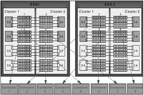
Use DB2 to stripe across containersFigure 1.16 shows how containers should be striped across arrays, across disk adapters, across clusters, and across ESS cabinets. This is done using the striping capabilities of DB2. Figure 1.16. Container placement on IBM ESS. Extent size for ESSTo stripe across multiple arrays in the ESS, assign a logical disk from each array to be used as a DB2 container. During writes , DB2 will write one extent to the first container, the next extent to the second container, and so on, until all eight containers have been addressed before cycling back to the first container. DB2 stripes across containers at the extent level, and the stripe size is specified as the extent size of the table space. Because the underlying ESS stripe size is 32 KB, using an extent size that is an integer multiple of 32 KB allows multiple ESS disks to be used within an array when a DB2 prefetch occurs. However, tests have shown that I/O performance is fairly insensitive to the selection of extent sizes, mostly due to the fact that ESS employs internal sequential detection and prefetch. Prefetch size for ESSThe table space prefetch size determines the degree to which separate containers can operate in parallel to handle I/O requests . Although larger prefetch sizes can enhance throughput of individual queries, mixed applications generally work best with moderately sized prefetch and extent sizes. To obtain maximum throughput, it is important to engage as many arrays as possible in the prefetch. What about logs on ESS?Some database specialists and consultants recommend not using RAID-5 to store database log files. Although this may be true with some RAID-5 implementations, it is not the same with IBM ESS. Some other RAID-5 implementations have not been able to handle database logging efficiently , due to a lack of one or more of the following:
Database logging normally consists of sequences of synchronous sequential writes to disk. These patterns may not be purely sequential, meaning that they may periodically rewrite certain physical records, but they do have a generally sequential trend. The physical record sizes are normally small and typically range between 4 and 64 KB, depending on the frequency of commit points and other factors. Log archiving functions, where an entire log file is copied to an archived space, also tend to consist of simple sequential read and write operations. When DB2 writes a log record, the ESS stores two copies of the log record in its cache (one in the cluster cache and the other in nonvolatile storage). The ESS will immediately indicate that the write is complete, once both copies have been stored safely. At this point, the log record is doubly protected. After a number of log records have been written, ESS will determine that this is a sequential write pattern. When data is moved asynchronously to disk, the cache manager sends one or more full stripes of data to the SSA disk adapter. The ESS cache manager and disk adapter write data to each of the disks in parallel, while at the same time internally calculating the parity and sending it to disk. This technique eliminates the traditional RAID-5 write penalty. Criteria for selecting ESS logical disk sizesIBM ESS can support a high degree of parallelism and concurrency within a single logical disk. Performance tests have indicated that a single logical disk consuming an entire array achieves the same performance as many smaller logical disks on the same array. However, logical disk size also affects systems management. Smaller logical disks allow for more granularity when managing storage, although they increase the number of logical disks seen by the operating system. Select an ESS logical disk size that allows for granularity and growth without proliferating the number of logical disks. TIP Make the DB2 table space prefetch size a multiple of the extent size multiplied by the number of containers in the table space, but do not make it more than 512 pages. Prefetch Size = min (512, Extent Size * Number of Containers) TIP Allocate the table space containers on separate RAID arrays to ensure that multiple arrays can be used in parallel. TIP Try to strike a reasonable balance between flexibility and manageability. A general recommendation is that there should be no fewer than two logical disks in an array, and a minimum logical disk size should be around 16 GB. Use a single logical disk size throughout the ESS. Eight logical disks per RAID array can be a reasonable balance. Smaller logical disks have the following attributes: Advantages:
Disadvantages:
Larger logical disks have the following attributes: Advantages:
Disadvantages:
Use ESS multi-pathingMulti-pathing is the use of hardware and supporting software to provide multiple access paths to the underlying disks from the host computer. When using ESS, this means that there needs to be at least two fibre or SCSI connections to each host computer from any component being multi-pathed. It also involves internal configuration of the ESS host adapters and volumes. Multi-pathing also requires installation of the IBM subsystem device driver (SDD) software on the host computer. Without this software, a single logical disk on multiple paths will appear as multiple different disks to the operating system. There are several benefits from using multi-pathing, including high availability, high bandwidth, and ease of performance management. A high-availability implementation is one in which an application can still access storage through an alternate path if a component on one path should fail. Multi-pathing for bandwidth means that there are enough access paths to the data so that the total bandwidth is not bound by the data throughput that other components of the system (i.e., CPUs) can sustain. Multi-pathing for ease of performance management means allowing multi-pathing software to balance the I/O workload across multiple available access paths automatically. |


EAN: 2147483647
Pages: 121
- The Second Wave ERP Market: An Australian Viewpoint
- The Effects of an Enterprise Resource Planning System (ERP) Implementation on Job Characteristics – A Study using the Hackman and Oldham Job Characteristics Model
- Context Management of ERP Processes in Virtual Communities
- Distributed Data Warehouse for Geo-spatial Services
- Relevance and Micro-Relevance for the Professional as Determinants of IT-Diffusion and IT-Use in Healthcare