Air Conditioning Systems
| In the simplest terms, HVAC units are really big air conditioners, not dissimilar to the air conditioning unit in your car, apartment, or house. The efficiency of a precision air conditioning system is based on two things:
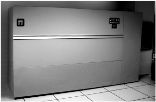
The following figure shows an HVAC unit and controls. Figure 8-1. HVAC Unit Chilled Liquid SystemsThe basic premise of a chilled liquid system is that air goes into the unit through its intake (at the top of most HVAC units) and is passed through a set of filters, some of which are electrically charged to attract dust particles and other contaminants . Once filtered, the air passes through a series of coils that contain fluid at much lower temperature than the air. A heat exchange between the temperature of the air and the temperature of the fluid in these coils occurs, lowering the temperature of the air. The cooled air is passed out of the HVAC unit at higher speed and pressure with fans that force it into the supply plenum (usually the raised floor). HVAC units can also have humidifiers which add an atomized stream of water to the air. This changes the RH of the air to keep it at the appropriate level. The fluid in the coils is sent out of the unit to cooling towers to expel the heat. The HVAC unit will have set points for both ideal temperature and humidity levels, like the thermostat in a house. Sensors located within the data center track both the temperature and humidity of the air. This information is fed back to the HVAC unit and the unit adjusts its heat transfer and the humidifier moisture level to meet its set points. Dry Conditioning SystemsIn areas that have high humidity, a dry conditioning system could be more appropriate than a chilled liquid system. A dry conditioning system uses a lithium chloride solution applied in a constant stream to a saturated cellulose honeycomb material. As outside air comes in contact with this lithium chloride solution, the water vapor in the air reacts with the solution. The solution absorbs humidity and generates heat, which cools and dehumidifies the air. This cooler and less humid air can then be sent to a secondary chilled liquid system. Since the air going into the chilled liquid system has already been partially cooled, less work and energy is expended to bring the air to the needed temperature and RH levels. Portions of the now heated lithium chloride solution are pumped through a filter system and heat exchanger. The heat exchanger drives a heat pump to assist in regenerating the lithium chloride solution, removing the heat and humidity, and prepare the solution to go through the process again. Since this system relies on water vapor to create the chemical reaction and cool the air, it is only appropriate in areas where the ambient humidity in the outside air is well above the ideal 45 percent needed in a data center. Areas like Atlanta, Georgia and Tokyo, Japan, are better suited to this kind of HVAC "preprocessing." It would not be as useful in areas with very low ambient humidity like Las Vegas, Nevada, or Phoenix, Arizona. Planning Air CirculationAir flow planning is critical because it affects the placement of data center racks. The racks have two footprints, physical and cooling. The cooling footprint is what you need to know at this stage of the design. If you have racks that cool side to side, you will need more clearance than if they're cooled top to bottom. You can't place two side-cooling machines next to each other with zero side clearance. Also, if machines are cooled front-to-back, the use of a back-to-back cooling model, alternating hot and cool aisles , is critical. Consider the air flow patterns of the storage and server equipment to be installed in the data center.
Since the equipment from different manufacturers can have different air flow patterns, you must be careful that the different units don't have conflicting patterns, for example, that the hot exhaust from one unit doesn't enter the intake of another unit. Sun equipment is usually cooled front-to-back or bottom-to-top. Bottom-to-top is the most efficient way to cool equipment, drawing directly from the supply plenum and exhausting to the return plenum in the ceiling. It also creates a more economical use of floor space since no open area to the sides of the equipment are needed for free cooling space. For more about air flow in general, see Chapter 6, "Implementing a Raised Floor." Downward Flow SystemOptimally, an air conditioning system with a cold plenum low, return plenum high ("downward") flow should be used. For a small amount of hardware space, appropriate conditions can be maintained with other designs. However, the air flow patterns in the downward flow design allow for the most efficient hardware cooling. These systems work by drawing air into the top of the HVAC unit, either from the room or from the return plenum (return air), where it is cleaned by air filter banks, and passed over a cooling coil. The conditioned air (supply air) is then pushed by large fans at the bottom of the unit into the plenum between the subfloor and raised floor. The forced air is directed into the computer space through cable cutouts , or perforated floor tiles. Once in the ambient room space, the conditioned air mixes with the hardware heat load by passing through the rack, absorbing heat, then flows back to the air conditioners through the return plenum for reconditioning. This produces an efficient air flow pattern using natural convection currents. The downward flow air conditioning system used in data centers is typically incorporated with a raised floor system. The raised floor should be 24 inches (60 cm) above the subfloor to allow space to run network and power cables, and for the passage of air. The modular tile design makes it easy to reconfigure hardware and air distribution patterns. When hardware is added, solid and perforated tiles can be positioned to deliver conditioned air to the hardware intakes. For more information on the raised floor system, see Chapter 6, "Implementing a Raised Floor." Overhead Air HandlersOverhead air introduction or upflow air conditioning should be avoided due to their associated turbulent air flow patterns. The following figure shows an example of the difference in efficiency between an upward and downward air flow system. Figure 8-2. Upward vs. Downward Air Flow Patterns The majority of the hardware in most data centers takes in air for cooling at the front or bottom of the unit and exhausts it out the back or top. Introducing conditioned air from the ceiling causes turbulence when the conditioned air meets the hot exhaust. A higher cooling load is needed to address this inefficiency. Centralized Air HandlingCentralized systems, using a single large air handling unit, should be avoided. The problems with centralized systems are:
Placement of HVAC UnitsHVAC units are placed depending on your heat load criteria, and this is one of the reasons that cooling is part of the RLU specifications. If 25 percent of your data center will contain 50 percent of the heat load, then equally distributing your HVAC units around the data center would not be the most efficient use of your cooling capacity. Where they are placed depends on the capacity of each unit to cool and deliver the air to the correct locations on the floor. You should work with your HVAC engineers to determine the ideal placement of your HVAC units for maximum efficiency. While it is critical to work with all of your contract professionals, it is particularly important to work with knowledgeable HVAC engineers . In many areas there are little or no building code requirements for HVAC systems used in data centers. If the room is a long thin rectangle, you can probably place the HVAC units along the perimeter of this room and get enough cold air volume to the center area. If the room is a large square, you can place units at the perimeter and down the center as well, creating in effect two long thin rectangles within the room. This creates zones of cold air at the required pressure for a given area to meet its cooling requirements. Additionally, software for simulations of air flow and heat transfer is available. "Flovent" software from Flomerics uses Computational Fluid Dynamics (CFD) techniques to allow for HVAC simulation of data center environments. These models can include raised floor height, obstructions under the floor, placement and percentage of perforated tiles, servers, storage systems, and the placement of HVAC units. Most HVAC systems require some liquid like water or coolant to exchange the heat from the air as it goes through the unit, and this liquid is moved outside of the room (and probably the building) to expel the heat it has absorbed. Pipes containing this liquid will be within, or quite close to, your data center. As you know, water and electricity are a nasty combination. If you put HVAC units on the floor, you must ensure that these pipes have troughs or channels to redirect the fluid out of the data center in the case of a pipe failure. One way to do this is to locate as many HVAC units as possible, perhaps all of them, outside the data center. The following figure shows how the mechanical rooms that house the HVAC units are connected just on the outside of the walls for the data center. Figure 8-3. Placement of HVAC Units Outside the Data Center Room All the pipes needed for these units can be located outside the data canter, as well. There should be a 4-inch barrier at the perimeter of the data center to prevent liquid from the pipes from entering the data center if a pipe were to fail. This also gives a clean access to the base of the HVAC unit to pump cold air under the floor with minimal obstruction. Since these units are outside the walls of the data center, the raised floor and dropped ceiling voids can be used as supply and return plenums, respectively. |
EAN: 2147483647
Pages: 142