Section 4.16. The Extensible Firmware Interface
4.16. The Extensible Firmware InterfaceIn this section, we look at the Extensible Firmware Interface (EFI), which is a specification for an interface between operating systems and platform firmware. x86-based Macintosh computers use EFI instead of Open Firmware. EFI is conceptually very similar to Open Firmware. Although it is platform independent in theory, EFI is primarily intended for the IA-32 and IA-64 architectures. 4.16.1. Legacy PainsThe primitive nature of the PC BIOS had long been an industry-wide problem even as the twenty-first century arrived. One reason for the longevity of the BIOS, and for its sustained primitivity, is the extremely successful MS-DOS (and clones), which was built on top of the BIOS. DOS programs call BIOS routines via software interrupts. For example, the BIOS disk routine corresponds to interrupt number 0x13 (INT 0x13). This is similar to many erstwhile Apple systems where the Macintosh ROM contained both low-level code and the higher-level Toolbox. Although the BIOS has seen numerous tweaks, improvements, extensions, and additions over the years, a traditional BIOS in a modern environment still has numerous severe limitations, such as the following.
Regardless of their nature, modern operating systems running on the x86 platform must interact with the BIOS via legacy interfaces at system startup. The processor starts up in real mode and typically remains in real mode even as an operating system kernel gains control, after which the kernel eventually switches the processor into protected mode. A representative legacy BIOS could be visualized as containing three sets of procedures: those that are the same on all BIOSs (the core procedures), those that are specific to chips on the platform (the silicon support procedures), and those that are specific to a system board. There are many "secret-sauce" elements in the BIOS. The BIOS APIs are very limited, and in general it is very hard to extend the BIOSit is a black box both to end users and to those wishing to develop preboot applications. Even if such developers license the BIOS source, the environment is expensive to develop for and deploy in.
4.16.2. A New BeginningThe PC world was rather late to adopt 64-bit computing. With the advent of 64-bit PCsthose based on Intel's Itanium Processor Family, or IA-64, for examplea better solution to the BIOS problem was sought. Even though the x86 real mode can be emulated in the IA-64 architecture, 64-bit PCs were introduced without the legacy BIOS. The IA-64 firmware was divided into three primary components: the Processor Abstraction Layer (PAL), the System Abstraction Layer (SAL), and the Extensible Firmware Interface (EFI). PAL abstracts the processor hardware implementation from the point of view of SAL and the operating system. Different processor models with potential implementation differences appear uniformly via PAL. Examples of the PAL layer's functionality include the following:
PAL has no knowledge of platform implementation details. Note, however, that PAL is part of the IA-64 architecture. The processor vendor supplies the firmware implementation of PAL, which resides in OEM flash memory. SAL provides an abstraction for the platform implementation, without any knowledge of processor implementation details. SAL is not part of the IA-64 architectureit is part of the Developer's Interface Guide for 64-bit Intel Architecture (DIG64). The OEM provides the firmware implementation of PAL.
As on IA-32 systems, Advanced Configuration and Power Interface (ACPI) exists on IA-64 as an interface for allowing the operating system to direct configuration and power management on the computer. ACPI is also a part of the firmwareit could be listed as the fourth primary component besides PAL, SAL, and EFI. Note that since EFI also exists for IA-32, only PAL and SAL are the parts of IA-64 firmware that are specific to IA-64. The remaining componentEFIcould be thought of as the grand solution to the PC BIOS problem. 4.16.3. EFIEFI can be traced back to the Intel Boot Initiative (IBI) program that started in 1998, based on a white paper by Intel engineer Andrew Fish. The EFI specificationdeveloped and maintained by a consortium of companiesdefines a set of APIs and data structures that are exported by a system's firmware and used by clients such as the following:
In a representative EFI system, a thin Pre-EFI Initialization Layer (PEI) might do most of the POST-related work traditionally done by the BIOS POST. This includes operations such as chipset initialization, memory initialization, and bus enumeration. EFI prepares a Driver Execution Environment (DXE) to provide generic platform functions that EFI drivers may use. The drivers themselves provide specific platform capabilities and customizations. 4.16.3.1. EFI ServicesThere are two classes of services available in the EFI environment: boot services and runtime services. Boot ServicesApplications that run only within the preboot environment make use of boot services, which include services for the following:
An operating system loader also uses boot services to determine and access the boot device, to allocate memory, and to create a functional environment for the operating system to start loading. At this point, an operating system loader could call the ExitBootServices() function, after which boot services are not available. Alternatively, an operating system kernel could call this function. Runtime ServicesRuntime services are available both before and after ExitBootServices() is called. This category includes the following types of services:
Although EFI was designed for IA-64-based computers, its scope was widened to include the next generation of IA-32 computers, with provisions for legacy BIOS compatibility through a Compatibility Support Module (CSM). The CSM consists of a series of drivers that cooperate with a legacy BIOS runtime component. It loads into memory in well-known legacy areas (below 1MB). Standard BIOS memory areas such as the BIOS Data Area (BDA) and the Extended BDA are initialized. The Boot Device Selection (BDS) mechanism appropriately selects either EFI or legacy BIOS. Figure 420 shows a conceptual view of the EFI architecture. Figure 420. The EFI architecture 4.16.3.2. EFI DriversEFI drivers can be built into the EFI implementation. Alternatively, they can come from the option ROM of a card or from a device supported natively by EFI. Most EFI drivers would conform to the EFI Driver Model. Such drivers are written in C and operate in a flat memory model. Driver images, which may be converted to EFI Byte Code (EBC), are typically compressed using Deflatea combination of LZ77[30] compression and Huffman coding. Examples of EFI driver types include the following:
EFI also supports drivers that may not conform to the EFI Driver Model. Examples of such drivers include the following:
An EFI protocol is a set of related interfaces. EFI drivers consume various protocols such as PCI I/O, Device Path, USB I/O, and USB Path. They also produce several protocols such as Simple Input, Simple Pointer, Block I/O, UGA Draw, UGA I/O, Simple Text Output, SCSI Block I/O, SCSI Pass-through, Network Interface Identification, Serial I/O, Debug Port, and Load File. EFI drivers are typically needed only for devices that must be used before the operating system starts running. The primary example is that of a storage device on which the operating system resides. The EFI driver for a storage device allows EFI to export block I/O services, which the bootloader uses to load the operating system kernel. 4.16.4. A Sampling of EFILet us now look at a few specific aspects of EFI, including examples of interacting with the EFI environment. 4.16.4.1. EFI NVRAMEFI defines an area of nonvolatile memory, or NVRAM, which is used to store both global and application-specific data in the form of variables. The NVRAM store can be programmatically accessedfor retrieval or storageusing the EFI API. Variables are stored using a two-level namespace: a globally unique ID (GUID) as the first level and variable names as the second level. Thus, it is possible for two variables with the same name to exist in two GUIDs without namespace collision. All architecturally defined global variables use a reserved GUID such as the following: #define EFI_GLOBAL_VARIABLE \ {8BE4DF61-93CA-11d2-AA0D-00E098032B8C}Examples of global variables include the currently configured language code (Lang), the ordered boot-option load list (BootOrder), the ordered driver-load option list (DriverOrder), and the device paths of the default input and output consoles (ConIn and ConOut, respectively). Application-specific variables, which are passed directly to EFI applications, are also stored in the NVRAM. Moreover, the NVRAM may be used for storing diagnostic data or other information that may be useful in failover and recovery scenarios, as long as the NVRAM has enough space to hold such information. 4.16.4.2. The Boot ManagerThe EFI firmware includes an application called the boot manager, which can load EFI bootloaders, EFI drivers, and other EFI applications. The boot manager consults global NVRAM variables to determine what to boot. It accesses bootable files from an EFI-defined file system or via an EFI-defined image-loading service. Figure 421 depicts a representative sequence of actions that occur after an EFI-based system is powered on. The core EFI firmware passes control to the boot manager, which uses the NVRAM facility to display a menu of installed bootable applications. In Figure 421, the user has selected an operating system bootloader for Mac OS X as the application to boot, which is launched by the boot manager. While executing in the EFI environment, the bootloader loads the kernel, collects any parameters that may exist in the NVRAM, and eventually hands off control to the kernel. If a boot application exits, control returns to the boot manager. Figure 421. Booting an operating system through EFI 4.16.4.3. The EFI ShellThe EFI environment optionally includes an interactive shell that allows a user to perform tasks such as the following:
The EFI specification does not cover a shell interface, but a representative EFI shell is a rudimentary command-line interpreteran EFI application implemented in C. Figure 422 shows examples of using an EFI shell (note that specifying the -b option to most commands causes the displayed output to break after one screen). Figure 422. Using the EFI shell
Apple did not include an EFI shell with the first x86-based Macintosh models. However, an EFI shell implementation that runs on these computers can be downloaded from Intel's web site. Note in Figure 422 that it is possible to have network connectivity within EFI's user-visible environment. 4.16.4.4. The GUID-Based Partitioning SchemeEFI defines a new partitioning scheme called the GUID Partition Table (GPT), which must be supported by an EFI firmware implementation. GPT uses GUIDs to tag partitions. Each disk is also identified by a GUID. This scheme includes several features that make it far superior to the legacy MBR-based partitioning scheme. Examples of such features include the following:
Figure 423 shows a GPT-partitioned disk. A dummy MBR is stored at logical block 0 for legacy compatibility. The primary header structure of a GPT is stored at logical block 1, whereas a backup is stored at the last logical block. A GPT header may never span more than one block on the device. Moreover, although GPT does not support nesting of partitions, it is legal to have a legacy MBR nested inside a GPT partition. However, EFI firmware does not execute the boot code on a legacy MBR. Figure 423. A GPT-partitioned disk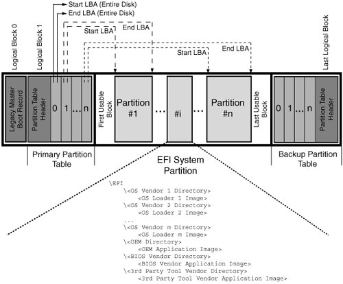
EFI supports a dedicated on-disk system partition called the EFI System Partition (ESP). The ESP uses the FAT-32 file system with support for long filenames. EFI drivers,[31] bootloaders, and other EFI applications can be stored on the ESP. The boot manager can run boot applications from this partition. Figure 424 shows the use of a GPT disk utility (diskpart.efi) to list the partitions on a disk. The Mac OS X gpt command can also be used for this purposewe will see an example of its use in Chapter 11.
Figure 424. Listing the partitions on a GPT-partitioned disk
4.16.4.5. Universal Graphics AdapterGiven the needs of modern preboot applications, VGA-based graphics support in a legacy BIOS environment is both very limited and hard to program with for several reasonsfor example, a maximum resolution of 640x480, a small framebuffer, and the use of palette modes. EFI defines the Universal Graphics Adapter (UGA) specification as a replacement for VGA and VESA. Any graphics device with UGA firmware can be considered a UGA device. It may also contain VGA firmware for compatibility. The EFI execution environment interprets UGA firmware, which is implemented in a high-level language. In particular, programming a UGA device does not require the programmer to deal with low-level details such as hardware registers. In the UGA model, the UGA firmware does not necessarily have to reside on a graphics deviceit may be part of the system firmware if the graphics device is onboard, or it may even reside on a regular storage device. UGA provides a draw protocol[32] for drawing on a video screen and an I/O protocol for creating a device-independent, operating systemspecific driver, which is simply a "lowest common denominator" driver in that it is not meant to replace a high-performance device-specific driver that would normally be part of an operating system. Nevertheless, a generic UGA driver may be used in the post-boot environment in scenarios such as the following:
Unlike VGA, the UGA firmware does not access the graphics hardware directly. It operates within a virtual machine. A vendor may provide a library that implements a thin logical layer above EFI, encapsulating a specific UGA firmware implementation. 4.16.4.6. EFI Byte CodeOption ROMs require different executable images for different processors and platforms. EFI defines an EFI Byte Code (EBC) Virtual Machine to abstract such differences. The firmware includes an EBC interpreter so that EFI images compiled to EBC are guaranteed to function on all EFI-compliant systems. C language source can be compiled into EBC and linked to yield drivers that run under the interpreter. The EBC Virtual Machine uses two sets of 64-bit registers: eight general-purpose registers and two dedicated registers. For data offsets, it uses natural indexing relative to a base addressinstead of a fixed number of bytes as an offset unit, it uses a natural unit defined as the operation sizeof(void *), rather than being a constant. This allows EBC to execute seamlessly on 64-bit and 32-bit systems.
Programs targeted for EBC must follow several restrictions. For example, they must not use floating-point, inline assembly, or C++. 4.16.4.7. Binary FormatEFI uses the PE32 binary format. The executable and object file formats under Microsoft Windows are called Portable Executable (PE) and Common Object File Format (COFF), respectively. A PE file is essentially a COFF file with a header that's compatible with MS-DOS 2.0. An optional header contains a magic number that further designates a PE file as PE32 or PE32+. The header also specifies the entry point for image execution.[33]
The subsystem ID in an EFI PE image header is either 0xa, 0xb, or 0xc, depending on whether an image is an EFI application, an EFI boot service driver, or an EFI runtime driver, respectively. 4.16.5. The Benefits of EFIEFI aims to be a powerful and modular firmware that is readily extensible, even by (power) users. The following list is a summary of key EFI benefits.
Despite having several features found in operating systems, EFI is not meant to be a replacement for a "real" operating system. Despite all its capabilities, EFI is a limited execution environment. Moreover, it is single-threaded and nonpreemptive. Nevertheless, EFI's preboot environment can facilitate robust solutions for secure network booting, secure network resetting, and remote system management. The latter employs bootable EFI programsor agentsthat allow remote firmware management, provisioning, and setup. |

EAN: 2147483647
Pages: 161