Section 4.3. Wireless Links and Transmission
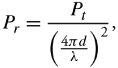
4.3. Wireless Links and TransmissionComputer networks can take advantage of the wireless infrastructure where physical wires cannot be laid out. An obvious example is mobile data communication, whereby mobile users attempt to connect and stay connected to the Internet. Wireless class education is another example; an instructor teaches class through wireless media, and students can follow the lecture with their portable computers from any location within a defined vicinity. One of the key challenges in wireless networking is the efficient utilization of the available transmission spectrum. Because the frequency spectrum available for wireless communication is normally limited, frequencies must be reused within the same geographic area. The spectrum used for wireless communications typically ranges up to several GHz. Security is also a concern in wireless networks. The open -air interface makes it difficult to prevent snooping. The link-level design techniques involve making trade-offs among the various parameters relevant to the link layer. The optimum design would involve the use of minimum bandwidth and transmit power while maintaining a high data rate, low latency, and low bit error rates (BER). These design challenges must be achieved in the presence of channel imperfections, such as flat fading, multipath effects, shadowing, and interference. Wireless links, both guided and unguided, are used for data communications. Wireless links use devices as an antenna for transmitting signals through vacuum , space , air , or substances . Electromagnetic waves can be propagated through the first three, as well as through water and wood. The frequency range depends on the type of substance. The two key challenges faced in overall design of efficient wireless links and transmission systems are the choice of antenna and wireless channels . 4.3.1. Choice of AntennaA good antenna in a wireless system can potentially enhance the signal-to-noise ratio. Antennas are classified in several ways. The two main types of antennas used in wireless systems are isotropic antennas and directional antennas . Isotropic AntennasIsotropic antennas transmit signals equally in all directions. Consider an isotropic transmitter that radiates P t watts equally in all directions, forming a sphere of flux with radius d . Given that the surface area of the sphere is 4 d 2 , power-flux density measured on the surface of the sphere used by a receiver located at distance d is Equation 4.2 At the other end of communication systems, P r , as the captured power, depends on the size and orientation of the antenna with respect to the transmitter. If we let a be the effective area of the receiving antenna, P t and P r are related by Equation 4.3 According to electromagnetic theory, the effective area of an isotropic antenna is obtained by a = Equation 4.4 where » is the wavelength of the signal obtained from Equation (4.1). In most propagation media other than free space, the received signal power varies inversely with d 3 or d 4 , compared to d 2 for free space. Directional AntennasDirectional antennas are used to mitigate unwanted effects. Directional antennas amplify the signal in a small angular range but attenuate the signal at all other angles. This helps reduce the power in the various multipath components at the receiver. Directional antennas can be used to reduce the effects of interference from other users. The antenna must be accurately pointed to the correct user and must follow the user 's path . This fact should lead to the development of smart antennas that can be used to track mobile users accurately by antenna steering. 4.3.2. Wireless ChannelsWireless communication is characterized by several channel impediments. A wireless channel is a portion of transmission bandwidth through which communication can be established. Channels are susceptible to interference and noise. The characteristics of a wireless channel vary with time and user movement. Most commercial wireless systems use radio waves in the ultrahigh frequency (UHF) band for communication. The UHF band ranges from 0.3 GHz to about 3 GHz. Satellite communication typically uses super-high frequency (SHF) band ranging from 3 GHz to 30 GHz. The transmitted signal reaches a receiver via three different paths: direct , scattering , and reflection . Signals arriving at a receiver through scattering and reflection are normally shifted in amplitude and phase. Wireless channels are characterized by four main characteristics: path loss , shadowing , multipath fading , and interference . Path LossPath loss is a measure of degradation in the received signal power. The path loss depends on the transmitted power and the propagation distance. An important measure of the strength of the received signal is the signal-to-noise ratio ( SNR ). If the average noise power at the receiver is P n , the signal-to-noise ratio is given by Equation 4.5 where we defined P r to be the captured power in Equation (4.4). The received signal power decreases for higher frequencies, since these signals carry more power. Thus, the path loss increases with higher frequencies. The error rate in the channel is reduced when the signal-to-noise ratio is maintained at a high level. The path loss, L p , is obtained from Equation (4.6): Equation 4.6 Note that the path loss is the ratio of transmitted power to received power.
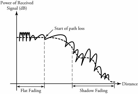
Shadow FadingAs it propagates through the wireless medium, a signal encounters various obstructions, such as buildings , walls, and other objects. Physical obstructions make the transmitted signal face signal attenuation. The variation of the received signal power due to these obstructions is called shadow fading . In typical cases, the variation in the received signal power because of shadow fading follows a Gaussian distribution. From Equation (4.3), the received signal power seems to be the same at equal distance from the transmitter. However, even when d is the same in Equation (4.3), the received signal power varies, since some locations face greater shadow fading than do others. Normally, the transmit power P t should be increased to compensate for the shadow-fading effect. Figure 4.2 shows the shadow-fading effect of a received signal. Figure 4.2. Flat fading, path loss, and shadow fading Flat and Deep FadingAt each wireless receiver, the received signal power fluctuates rapidly with time and slightly with distances, a phenomenon called flat fading . Figure 4.2 shows a received signal power that varies with distance. The figure shows that the received signal power falls from its average value. This phenomenon, whereby the received signal power falls below the value required to meet link-performance constraints, is called deep fading . Doppler Frequency ShiftLet … r be the relative velocity between a transmitter and a receiver. The shift in the frequency of the transmitted signal caused by the relative velocity is called Doppler shift and is expressed by f D : Equation 4.8 where » is the wavelength of the transmitted signal. As the relative velocity changes with time, the Doppler shift also varies. In frequency modulations, this shift could result in an increase in the bandwidth of the signal. In most scenarios, the Doppler shift can be of the order of several Hz, whereas the signal bandwidth is of the order of several KHz. Thus, the effect of Doppler shift is negligible in these cases. InterferenceThe limited frequency spectrum in wireless channels leads to frequency reuse at spatially separated locations. Frequency reuse can lead to interference . The interference can be reduced by using more complex systems, such as dynamic channel allocation, multiuser detection, and directional antennas. Interference can also result from adjacent channels if they occupy frequencies outside their allocated frequency bands, although interference can be reduced by having a guard band between channels. Interference can also result from other users and other systems operating in the same frequency band. Certain filters and spread-spectrum techniques are used to eliminate this type of interference. 4.3.3. Capacity Limits of Wireless ChannelsCluade Shannon derived an analytical formula for the capacity of communication channels. The capacity of a channel in bits per second is given by Equation 4.9 where B is the channel bandwidth, and SNR is the signal-to-noise ratio at the receiver. Shannon's formula gives only a theoretical estimate and assumes a channel without shadowing, fading, and intersymbol interference effects. For wired networks, Shannon's formula gives a good estimate of the maximum achievable data rates. For wireless channels, the achievable data rate is much lower than the one suggested by Shannon's formula. The reason is that the channel characteristics vary with time, owing to shadowing, fading, and intersymbol interference. 4.3.4. Channel CodingChannel coding is a mechanism used to make channels immune to noise and to correct errors introduced by the channel. This process involves adding some redundant bits to the transmitted information. These redundant bits can be used for error detection and correction. The use of channel coding can eliminate the need for retransmissions when channel-errors occur. The redundant bits caused can be used to correct the errors and thereby reduce the transmit power and achieve a lower BER. Forward error correction (FEC) is a commonly used scheme for channel coding. FEC schemes normally increase the signal bandwidth and lower the data rate. The automatic repeat request (ARQ) scheme explained in previous chapters is normally used along with FEC, as FEC is not sufficient for implementing channel coding. Turbo codes have also been successful in achieving data rates near Shannon's capacity. Turbo codes, however, are very complex and have large delays. 4.3.5. Flat-Fading CountermeasuresThe common techniques used to combat flat fading are diversity , coding and interleaving , and adaptive modulation . With diversity multiple independent fading paths are combined at the receiver to reduce power variations. These independent fading paths can be obtained by separating the signal in time, frequency, or space. Space diversity is one of the most commonly used and effective diversity techniques. An antenna array is used to achieve independent fading paths. Antenna elements in the array are spaced at least one-half wavelength apart. Coding and interleaving is another technique used to counter flat fading. In general, flat fading causes errors to occur in bursts. With coding and interleaving, these burst errors are spread over multiple code words. The adjacent bits from a single code word are spread among other code words to reduce the burst of errors, because burst errors affect adjacent bits. The code words passed to the decoder of the interleaving process contain at most one bit error. FEC channel coding can be used to correct these errors. Adaptive modulation schemes adjust to channel variations. The transmission scheme adapts to the varying channel conditions, based on an estimate that is sent back to the transmitter. The data rate, transmit power, and coding scheme are tailored, based on the received channel estimate. The channel estimate varies, depending on the amount of flat fading. These adaptive schemes help reduce BER and increase efficiency. The adaptive schemes do not function properly if a channel cannot be estimated or if the channel characteristics change very rapidly. It should be noted that the feedback scheme for conveying the channel estimate to the transmitter requires additional bandwidth. 4.3.6. Intersymbol Interference CountermeasuresThe techniques used to combat intersymbol interference (ISI) can be classified into signal-processing techniques and antenna solutions. The signal-processing techniques, which attempt to compensate for ISI or reduce the influence of ISI on the transmitted signal, include equalization, multicarrier modulation, and spread-spectrum techniques. The antenna solutions attempt to reduce ISI by reducing the delay between the multipath components and include directive beams and smart antennas. The equalization method compensates for ISI at the receiver through channel inversion. The received signal is passed through a linear filter with inverse frequency response, making ISI zero. The noise has to be reduced before passing the signal through the inverse filter. This is done by a linear equalizer called the minimum mean square equalizer. Given a large variation in the channel frequency response, nonlinear decision-feedback equalizer (DFE) is used. DFE uses the ISI information from the previously detected symbols to achieve equalization. DFE is more complex and achieves a much lower BER. Other equalization techniques are the maximum- likelihood sequence and turbo equalization. These schemes perform better than DFE but are much more complex. The equalizer techniques require an accurate channel estimate to compensate correctly for ISI. As a result, equalizer techniques may not work well for channels in which the characteristics change rapidly. Multicarrier modulation is another technique used to reduce the effect of ISI. The transmission bandwidth is divided into a number of narrow slots called subchannels. The message signal containing the information to be transmitted is also divided into an equal number of slots. Each of these slots is modulated on one of the subchannels. The resulting sequence is transmitted in parallel. The subchannel bandwidth is maintained less than the coherent bandwidth of the channel. This results in a flat fading instead of a frequency-selective fading in each channel, thereby eliminating ISI. The subchannels can be either nonoverlapping or overlapping. The overlapping subchannels are referred to as orthogonal frequency division multiplexing (OFDM). This technique improves the spectral efficiency but results in a greater frequency selective fading, thereby decreasing the signal-to-noise ratio. 4.3.7. Orthogonal Frequency Division Multiplexing (OFDM)In orthogonal frequency division multiplexing (OFDM), transmitters generate both the carrier and the data signal simultaneously . OFDM is not a multiple-access technique, as there is no common medium to be shared. The entire bandwidth is occupied by a single source of data. Instead of being transmitted serially , data is transmitted in parallel over a group of subcarriers. Since the carriers are orthogonal to one another, the nulls of one carrier coincide with the peak of another subcarrier, resulting in the possibility of extracting the subcarrier of interest. Contrary to the traditional FDM technique, the spectrum of channels in OFDM significantly overlap. The process of digital signal generation used in OFDM is based on inverse fast Fourier transform (FFT) (see Figure 4.3). A serial-to-parallel converter (S/P) converts the serial bits to be transmitted into parallel format. The number of subcarriers and the type of digital communication technique used determine the typical number of bits in parallel. Thus, the incoming data is divided into a large number of carriers. Then map and demap act as digital modulator and demodulator, respectively. Typically, a quadrature amplitude modulation (QAM) or quadrature phase shift keying (QPSK) is used as modulator. Figure 4.3. A block diagram of the OFDM technique The heart of this technique is an inverse fast Fourier transform (FFT), in which a carrier frequency is generated based on the location of the stored value. This produces a set of time-domain samples. At the receiver, individual subchannels can be completely separated by FFT only when there is no intersymbol interference in an add cyclic prefix acting as a band guard. Note that as the signal travels through the medium, the signal arrives at the receiver at different instances, owing to multipath propagation, resulting in a delay spread leading to ISI. A simple solution to overcome ISI is to widen the symbol duration. This can be achieved by increasing the number of carriers, causing the distortion to become insignificant. At the receiver, the time waveform is digitized and converted back to a symbol, using FFT. The incoming carrier signal is tracked coherently and sampled in order to be sent to FFT. The time-domain samples are needed at FFT in order to extract the amplitude and phase of the signals. Depending on the amplitude and phase extracted over one symbol time, the frequency-domain representation of the signals obtained. The results are demapped into their original bitstreams, depending on the digital demodulator applied. OFDM signal reception involves a challenging task of time-frequency domains, sampling, and clock synchronization, as well as channel estimations. |
EAN: 2147483647
Pages: 211