Section 15.4. Node-Level Multicast Algorithms
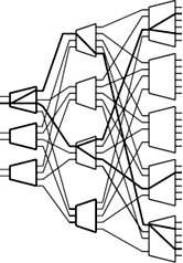
15.4. Node-Level Multicast AlgorithmsMulticasting techniques can also be used at the router level. To implement a multicast connection, a binary tree is normally constructed with the source switch port at the root and the destination switch ports at the leaves . Internal nodes act as relay points that receive packets and make copies. A number of such multicast methods are used. One is a tree-based multicast algorithm using a separate copy network. The Boolean splitting multicast algorithm is used for multistage switches. The third technique the packet recirculation multicast algorithm . The fourth is multicasting in three-dimensional switches . 15.4.1. Tree-Based Multicast AlgorithmImagine that a multicast tree algorithm must be applied on a multistage switch fabric, as shown in the expansion switch in Figure 15.10. Multicasting is implemented as a tree structure. A source generates a packet and sends it out to the first crossbar switch. The packet may have a field that specifies how many copies of this packet are to be made. All copies may be destined for other crossbars, in which more copies of the packet are made, and some packets may move to their destinations. Figure 15.10. Tree-based multicasting in an expansion switch For implementing a tree-based multicast algorithm , the copying tasks in multistage switch fabrics typically involve a copy switch and a routing switch. An example of such systems consists of two Bene Define:
Begin Tree-Based Multicast AlgorithmIn the copy network shown in Figure 15.11, packets are replicated as designated by the initial global number of copies , F , given in the routing-control field of the packet header. The global number of copies refers to the total number of packet copies requested . Let F j be the remaining number of copies of a packet when it arrives at stage j , and let f j be the number of copies made locally at stage j . First, the algorithm initializes F j to F and f j to 1. The copying method is such that the replication of the packets takes place stage by stage within the network in order to distribute the traffic as evenly as possible. The routing is either point to point or multipoint connection. Figure 15.11. Tree-based multicasting through a three-stage copy network followed by a routing network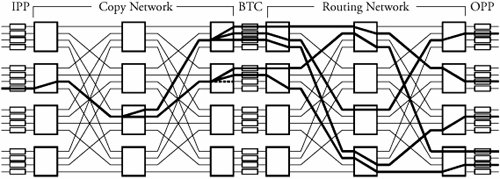 Consider a copy network with k stages. When multipoint connections are requested, a packet is routed randomly in the first k - 1 stages. In the last k stages, the packet is copied . The operation This technique reduces the hardware complexity in the controller. If the final number of copies that appear on the outputs is more than requested, the unnecessary packet copies can be easily thrown away. This task is completed by the broadcast translated circuit (BTC), shown in Figure 15.11. BTCs receive all the copies of a packet. A central monitoring mechanism for all BTCs compares the number of requested copies read from the packet's header and the number of copies made in the copy network. This mechanism then decides to remove unused copies, based on this comparison. For the routing network, routing is similar to that in a point-to-point copy network.
15.4.2. Boolean Splitting Multicast AlgorithmThe Boolean splitting multicast algorithm is a method of copying packets in any space-division switch fabric with n inputs or outputs constructed with 2 x 2 switch elements and therefore with log 2 n stages. Consider a Banyan network in which switching nodes replicate packets based on 2-bit header information. The following algorithm presents multicast steps within a copy network. Define:
Begin Boolean Splitting Multicast Algorithm
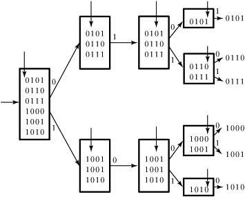
The switch fabric replicates packets according to a Boolean interval-splitting algorithm, based on the address interval in the new header. An output port address of the switch fabric that receives a copy of the packet is represented by two k -bit binary numbers. Suppose that a packet arrives at an arbitrary crossbar at stage j - 1 from a previous crossbar j . If we represent the minimum number by a k -bit address a k ... a 1 and the maximum number by a k -bit address A k ... A 1 , we can make the following observations: If a j = A j = 0 or a j = A j = 1, the packet is sent out on crossbar output 0 or 1, respectively. If a j = 0 and A j = 1, the network replicates the packet and sends both packets out on both links 0 and 1. If replication takes place, the packet header needs to be modified by splitting the original address interval into two subintervals, which can be expressed by the two following main recursions: a j + 1 = a j and A j + 1 = A k ... A k - (j - 1 ) 01 ... 1 for the packet sent out on Link 0, and a j + 1 = a k ... a k - (j - 1 ) 10 ... 0, and A j + 1 = A j for the packet sent out on Link 1. This modification is a routine operation, meaning that it is independent of the header contents and can be considered built-in hardware.
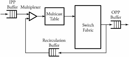
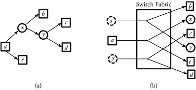
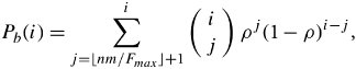
15.4.3. Packet Recirculation Multicast AlgorithmPacket recirculation ( recycling ) is another feasible method for constructing large switching fabrics for broadband switching applications. To implement a multicast connection, a binary tree is constructed with the source port at its root and the destination switch port at its leaves. This technique can be used for almost all kinds of space-division switch fabrics. If a switch fabric is constructed by a multistage interconnected network, internal crossbars can act as relay points to accept packets and recycle them back into the switch fabric after packet relabeling. New labels carry the information about the destination pair, identifying the next two switch ports to which they are to be sent. Figure 15.13 illustrates the recirculation technique. A multicast table provides an output port/IP address pair. This pair is added to the packet header; thus, two additional bits indicate whether the pair is to be recirculated again. An IPP buffer holds packets received from the input link and forwards them to the switching network. An OPP buffer holds packets waiting to be transmitted on outgoing links. A recirculation buffer provides buffering to the packets that need to be recycled. Figure 15.13. Recirculation multicasting Packet recirculation and copying within the switch fabric is straightforward. Figure 15.14 illustrates packet recirculation and copying. Suppose that a is a source that generates packets to be delivered to output ports b , c , d , and e and that x and y are relay points. Suppose that a packet entering at input port a must have several copies. For such a packet, there may be entries of the type ( x , j ) and ( e , k ) in the multicast table. This can be interpreted as making two copies of the packet: one to be recirculated back to port x on address j ; the other one, to port e with address k . The multicast table entry at x may now have entries ( b , n ) and ( y , m ), as seen. Typically, each packet header has 2 bits to indicate whether a packet needs to be recirculated. Figure 15.14. Within the switch fabric of routers: (a) packet recirculation and (b) copying In summary, an end point that is added needs to have a parent. A good candidate is the one that does not have heavy recirculation traffic. Like the parent of the new end point, the intermediate point also is new, so it has to be put into the multicast table entry of another node, which becomes the grandparent of the new end point, whose child will now become a sibling of the new end point. To remove a connection, we can consider two cases. We should examine whether the output to be removed has no grandparent but its sibling has children; in that case, we replace the parent's multicast table entry with the sibling's children. If the output to be removed has no grandparent and its sibling has no children, we simply drop the output to be removed from its parent's multicast table entry, and the connection reverts to a simple point-to-point connection. Note that since packets must be resequenced when they exit from the system, the resequencing buffer at the output port processor (OPP) of a router must be dimensioned to delay packets long enough so that slow packets have a chance to catch up with fast packets. 15.4.4. Multicasting in Three-Dimensional Switches This switch uses a Clos network as a building block module. An n -port Clos network is a nonblocking network if k Figure 15.15. Three-dimensional multiplexed Clos network At the first stage, no routing decision needs to be made. The first-stage switch elements maintain a table that indicates utilization of the center-stage arrays. This table is created on the basis of back-pressure information obtained from the center-stage arrays. A center-stage element least used at any particular time gets the highest priority. In fact, this table can be shared by all the first-stage arrays. Once a multicast packet arrives at the center-stage array, the switch looks at the first g bits of every address, where g = log 2 n/d . The packet is then split according to the number of distinct k bits found. The maximum number of new packets that can be created is n/d . All addresses with the same first g bits are sent to the corresponding switch element in the last stage. Also, since four distinct addresses are identified by the first 2 bits in our example, the packet is split four ways. The final stage (stage 3) looks at the remaining l bits, where l = log 2 n , in each address of the multicast packet received by the last-stage array. The packet is again split according to the number of different sets of l bits found. The maximum number of packets at this stage is l . The packets are then sent to the appropriate output port corresponding to the last l bits. If a packet is split, the header has to be modified. The new header contains the addresses with the same initial g bits. A multicast packet on a particular input port requesting F copies of a packet can distribute the request equally between the parallel planes. This reduces the load on any particular plane, leading to a reduction in the use of buffers. An analysis of a three-dimensional Clos network is based on the blocking probability P b (i) for input number i out of n : Equation 15.1 where is the offered load per input, and F max is the maximum number of copies requested by any packet. For better performance, a priority is assigned to each plane on the basis of usage. Therefore, planes that are being used less, as determined by the back-pressure information, are given higher priorities. The distribution of multicast packets among planes is done by using the following algorithm. Begin Multicast Algorithm in 3-D Switches
A distribution circuit at the input has the processing ability to take the packet header and modify it according to the algorithm for distribution of packets to the planes. Some fields are added on top of the original packet. In fact, an original packet is encapsulated into this new packet with the new packet header. |
 networks for constructing the copying and routing networks. The following algorithm presents the multicast steps within a copy network with
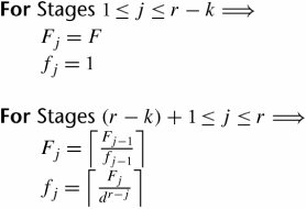


 2
2 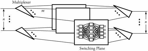
EAN: 2147483647
Pages: 211