IEEE 802.11a: OFDM PHY Specification for the 5 GHz Band
|
|
Supplementto IEEE Standard for Information technology-Telecommunications and information exchange between systems-Local and metropolitan area networks-Specific requirements Part 11: Wireless LAN Medium Access Control (MAC) and Physical Layer (PHY) specifications, High-speed Physical Layer in the 5 GHz Band, IEEE 802.11a-1999.
Concepts and Overview
IEEE 802.11a specifies the PHY entity for an orthogonal frequency division multiplexing (OFDM) system and the additions that have to be made to the base standard to accommodate the OFDM PHY. The radio frequency LAN system is initially aimed for the 5.15-5.25, 5.25-5.35, and 5.725-5.825 GHz unlicensed national information structure (U-NII) bands, as regulated in the United States by the Code of Federal Regulations, Title 47, Section 15.407. The OFDM system provides a wireless LAN with data payload communication capabilities of 6, 9, 12, 18, 24, 36, 48, and 54 Mbps. The support of transmitting and receiving at data rates of 6, 12, and 24 Mbps is mandatory. The system uses 52 subcarriers that are modulated using binary or quadrature phase shift keying (BPSK/QPSK), 16-quadrature amplitude modulation (QAM), or 64-QAM. Forward error correction coding (convolutional coding) is used with a coding rate of 1/2, 2/3, or 3/4.
Scope of the Standard This subclause describes the PHY services provided to the IEEE 802.11 wireless LAN MAC by the 5 GHz (bands) OFDM system. The OFDM PHY layer consists of two protocol functions, as follows (see Figure 6-4):
-
A PHY convergence function, which adapts the capabilities of the physical medium dependent (PMD) system to the PHY service. This function is supported by the physical layer convergence procedure (PLCP), which defines a method of mapping the IEEE 802.11 PHY sublayer service data units (PSDU) into a framing format suitable for sending and receiving user data and management information between two or more stations using the associated PMD system.
-
A PMD system whose function defines the characteristics and method of transmitting and receiving data through a wireless medium between two or more stations, each using the OFDM system.
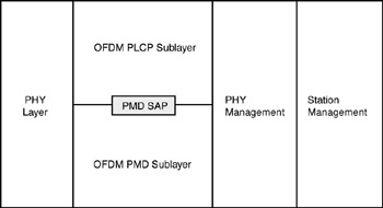
Figure 6-4: PMD layer reference model
OFDM PHY Functions The 5 GHz OFDM PHY contains three functional entities: the (i) PMD function, the (ii) PHY convergence function, and (iii) the layer management function. The OFDM PHY service is provided to the MAC through the PHY service primitives. The service of a layer or sublayer is the set of capabilities that it offers to a user in the next higher layer (or sublayer). Abstract services are specified here through the service primitives and parameters that characterize each service. This definition is independent of any particular implementation.
PLCP Sublayer In order to allow the IEEE 802.11 MAC to operate with minimum dependence on the PMD sublayer, a PHY convergence sublayer is defined. This function simplifies the PHY service interface to the IEEE 802.11 MAC services.
PMD Sublayer The PMD sublayer provides a means to send and receive data between two or more stations. This clause is concerned with the 5 GHz band using OFDM modulation.
PHY Management Entity (PLME) The PLME performs management of the local PHY functions in conjunction with the MAC management entity.
OFDM PHY Specific Service Parameter List
Introduction The architecture of the IEEE 802.11 MAC is intended to be PHYindependent. Some PHY implementations require medium management state machines running in the MAC sublayer in order to meet certain PMD requirements. These PHY-dependent MAC state machines reside in a sublayer defined as the MAC sublayer management entity (MLME). In certain PMD implementations, the MLME may need to interact with the PLME as part of the normal PHY SAP primitives. These interactions are defined by the PLME parameter list currently defined in the PHY service primitives as TXVECTOR and RXVECTOR. The list of these parameters, and the values they may represent, are defined in the specific PHY specifications for each PMD. This subsection addresses the TXVECTOR and RXVECTOR for the OFDM PHY.
TXVECTOR Parameters The parameters in Table 6-9 are defined as part of the TXVECTOR parameter list in the PHY-TXSTART.request service primitive.
| Parameter | Associate primitive | Value |
|---|---|---|
| LENGTH | PHY-TXSTART.request (TXVECTOR) | 1-4,095 |
| DATA RATE | PHY-TXSTART.request (TXVECTOR) | 6, 9, 12, 18, 24, 36, 48, and 54 (Support of 6, 12, and 24 data rates is mandatory.) |
| SERVICE | PHY-TXSTART.request (TXVECTOR) | Scrambler initialization: 7 null bits + 9 reserved null bits |
| TXPWR_LEVEL | PHY-TXSTART.request (TXVECTOR) | 1-8 |
RXVECTOR Parameters The parameters listed in Table 6-10 are defined as part of the RXVECTOR parameter list in the PHY-RXSTART.indicate service primitive.
| Parameter | Associate primitive | Value |
|---|---|---|
| LENGTH | PHY-RXSTART.indicate | 1-4,095 |
| RSSI | PHY-RXSTART.indicate (RXVECTOR) | 0-RSSI maximum |
| DATARATE | PHY-RXSTART.indicate (RXVECTOR) | 6, 9, 12, 18, 24, 36, 48, and54 |
| SERVICE | PHY-RXSTART.indicate (RXVECTOR) | Null |
OFDM PLCP Sublayer
Introduction The mechanism described in this section provides a convergence procedure in which PSDUs are converted to and from PPDUs. During transmission, the PSDU is provided with a PLCP preamble and header to create the PPDU. At the receiver, the PLCP preamble and header are processed to aid in demodulation and delivery of the PSDU.
PLCP Frame Format Figure 6-5 shows the format for the PPDU including the OFDM PLCP preamble, OFDM PLCP header, PSDU, tail bits, and pad bits. The PLCP header contains the following fields: LENGTH, RATE, a reserved bit, an even parity bit, and the SERVICE field. In terms of modulation, the LENGTH, RATE, reserved bit, and parity bit (with six 'zero' tail bits appended) constitute a separate single OFDM symbol, denoted SIGNAL, which is transmitted with the most robust combination of BPSK modulation, and a coding rate of R =1/2. The SERVICE field of the PLCP header and the PSDU (with six 'zero' tail bits and pad bits appended), denoted as DATA, are transmitted at the data rate described in the RATE field and may constitute multiple OFDM symbols. The tail bits in the SIGNAL symbol enable decoding of the RATE and LENGTH fields immediately after the reception of the tail bits. The RATE and LENGTH are required for decoding the DATA part of the packet. In addition, the CCA mechanism can be augmented by predicting the duration of the packet from the contents of the RATE and LENGTH fields, even if the data rate is not supported by the station.
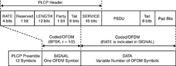
Figure 6-5: PPDU frame format
Overview of the PPDU Encoding Process The encoding process is composed of many detailed steps, which are summarized herewith.
-
Produce the PLCP preamble field, composed of 10 repetitions of a 'short training sequence' (used for AGC convergence, diversity selection, timing acquisition, and coarse frequency acquisition in the receiver) and two repetitions of a 'long training sequence' (used for channel estimation and fine frequency acquisition in the receiver), preceded by a guard interval (GI). Refer to the standard for details.
-
Produce the PLCP header field from the RATE, LENGTH, and SERVICE fields of the TXVECTOR by filling the appropriate bit fields. The RATE and LENGTH fields of the PLCP header are encoded by a convolutional code at a rate of R = 1/2, and are subsequently mapped onto a single BPSK encoded OFDM symbol, denoted as the SIGNAL symbol. In order to facilitate a reliable and timely detection of the RATE and LENGTH fields, six 'zero' tail bits are inserted into the PLCP header. The encoding of the SIGNAL field into an OFDM symbol follows the same steps for convolutional encoding, interleaving, BPSK modulation, pilot insertion, Fourier transform, and prepending a GI as described subsequently for data transmission at 6 Mbps. The contents of the SIGNAL field are not scrambled. Refer to the standard for details.
-
Calculate from the RATE field of the TXVECTOR the number of data bits per OFDM symbol (N DBPS), the coding rate (R), the number of bits in each OFDM subcarrier (N BPSC), and the number of coded bits per OFDM symbol (N CBPS). Refer to the standard for details.
-
Append the PSDU to the SERVICE field of the TXVECTOR. Extend the resulting bit string with 'zero' bits (at least six bits) so that the resulting length will be a multiple of N DBPS. The resulting bit string constitutes the DATA part of the packet. Refer to the standard for details.
-
Initiate the scrambler with a pseudorandom nonzero seed, generate a scrambling sequence, and XOR it with the extended string of data bits.
Refer to the standard for details.
-
Replace the six scrambled 'zero' bits following the 'data' with six nonscrambled 'zero' bits.
(Those bits return the convolutional encoder to the 'zero state' and are denoted as 'tail bits.') Refer to the standard for details.
-
Encode the extended, scrambled data string with a convolutional encoder (R = 1/2). Omit (puncture) some of the encoder output string (chosen according to the 'puncturing pattern') to reach the desired coding rate. Refer to the standard for details.
-
Divide the encoded bit string into groups of N CBPS bits. Within each group, perform an 'interleaving' (reordering) of the bits according to a rule corresponding to the desired RATE. Refer to the standard for details.
-
Divide the resulting coded and interleaved data string into groups of N CBPS bits. For each of the bit groups, convert the bit group into a complex number according to the modulation encoding tables. Refer to the standard for details.
-
Divide the complex number string into groups of 48 complex numbers. Each such group will be associated with one OFDM symbol. In each group, the complex numbers will be numbered 0 to 47 and mapped hereafter into OFDM subcarriers numbered -26 to -22, -20 to -8, -6 to -1, 1 to 6, 8 to 20, and 22 to 26. The subcarriers -21, -7, 7, and21 are skipped and, subsequently, used for inserting pilot subcarriers. The '0' subcarrier, associated with center frequency, is omitted and filled with zero value. Refer to the standard for details.
-
Four subcarriers are inserted as pilots into positions +21, +7, 7, and 21. The total number of the subcarriers is 52 (48 = 4). Refer to the standard for details.
-
For each group of subcarriers +26 to 26, convert the subcarriers to a time domain using an inverse Fourier transform. Prepend to the Fourier-transformed waveform a circular extension of itself thus forming a GI, and truncate the resulting periodic waveform to a single OFDM symbol length by applying time domain windowing. Refer to the standard for details.
-
Append the OFDM symbols one after another, starting after the SIGNAL symbol describing the RATE and LENGTH. Refer to the standard for details.
-
Up-convert the resulting complex baseband waveform to an RF frequency according to the center frequency of the desired channel and transmit. Refer to the standard for details.
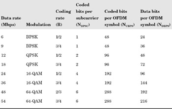
RATE-Dependent Parameters The modulation parameters dependent on the data rate used is set according to Table 6-11.
Table 6-11. Rate-dependent parameters
Timing Related Parameters Table 6-12 is the list of timing parameters associated with the OFDM PLCP.
| Parameter | Value |
|---|---|
| NSD: Number of data subcarriers | 48 |
| NSP: Number of pilot subcarriers | 4 |
| NST: Number of subcarriers, total | 52 (NSD + NSP) |
| DF: Subcarrier frequency spacing | 0.3125 MHz ( = 20 MHz/64) |
| TFFT: IFFT/FFT period | 3.2 µs (1/DF) |
| TPREAMBLE: PLCP preamble duration | 16 µs (TSHORT + TLONG) |
| TSIGNAL: Duration of the SIGNAL PBSK-OFDM symbol | 4.0 mµs (TGI + TFFT) |
| TGI: GI duration | 0.8 µs (TFFT/4) |
| TGI2: Training symbol GI duration | 1.6 µs (TFFT/2) |
| TSYM: Symbol interval | 4 µs (TGI + TFFT) |
| TSHORT: Short training sequence duration | 8 µs (10 x TFFT/4) |
| TLONG: Long training sequence duration | 8 µs (TGI2 + 2 x TFFT) |
Mathematical Conventions in the Signal Descriptions The transmitted signals will be described in a complex baseband signal notation. The signal actually transmitted relates to the complex baseband signal as follows:
r(RF)(t) = Re{r<t>exp<j2pfct>} (1) where Re(.) represents the real part of a cokplex variable. fc denotes the carrier center frequency.
The transmitted baseband signal is composed of contributions from several OFDM symbols.
rPACKET(t) rPREAMBLE(t) + rSIGNAL(t-tSIGNAL ) + rDATA(t-tDATA) (2)
PLCP Preamble (SYNC) The PLCP preamble field is used for synchronization. It consists of 10 short symbols and two long symbols that are shown in Figure 6-6.
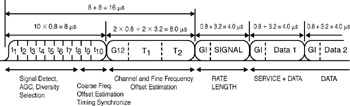
Figure 6-6: OFDM training structure
Figure 6-6 shows the OFDM training structure (PLCP preamble), where t1 to t10 denote short training symbols and T1 and T2 denote long training symbols. The PLCP preamble is followed by the SIGNAL field and DATA. The total training length is 16 µs. The dashed boundaries in the figure denote repetitions due to the periodicity of the inverse Fourier transform. A short OFDM training symbol consists of 12 subcarriers.
Signal Field (SIGNAL) The OFDM training symbol is followed by the SIGNAL field, which contains the RATE and the LENGTH fields of the TXVECTOR. The RATE field conveys information about the type of modulation and the coding rate as used in the rest of the packet. The encoding of the SIGNAL single OFDM symbol is performed with BPSK modulation of the subcarriers and using convolutional coding at R =1/2. The encoding procedure includes convolutional encoding, interleaving, modulation map- ping, pilot insertion, and OFDM modulation. The contents of the SIGNAL field are not scrambled.
The SIGNAL field is composed of 24 bits, as illustrated in Figure 6-7. The four bits 0 to 3 encode the RATE. Bit 4 is reserved for future use. Bits 5-16 encode the LENGTH field of the TXVECTOR, with the least significant bit (LSB) being transmitted first.
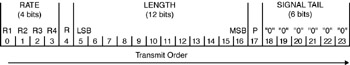
Figure 6-7: SIGNAL field bit assignment
DATA Field The DATA field contains the SERVICE field, the PSDU, the TAIL bits, and the PAD bits, if needed.
Service Field (SERVICE) The IEEE 802.11 SERVICE field has 16 bits, which are denoted as bits 0-15. The bit 0 is transmitted first in time. The bits from 0-6 of the SERVICE field, which are transmitted first, are set to zeros and are used to synchronize the descrambler in the receiver. The remaining nine bits (7-15) of the SERVICE field are reserved for future use. All reserved bits are set to zero. Refer to Figure 6-8.
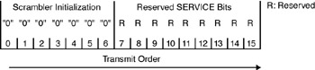
Figure 6-8: SERVICE field bit assignment
PPDU Tail Bit Field (TAIL) The PPDU tail bit field is six bits of '0,' which are required to return the convolutional encoder to the 'zero state.' This procedure improves the error probability of the convolutional decoder, which relies on future bits when decoding and which may be not be available past the end of the message. The PLCP tail bit field is produced by replacing six scrambled 'zero' bits following the message end with six nonscrambled zero bits.
Pad Bits (PAD) The number of bits in the DATA field is a multiple of N CBPS, the number of coded bits in an OFDM symbol (48, 96, 192, or 288 bits). To achieve that, the length of the message is extended so that it becomes a multiple of N DBPS, the number of data bits per OFDM symbol. At least six bits are appended to the message, in order to accommodate the TAIL bits.
Subcarrier Modulation Mapping OFDM subcarriers are modulated by using BPSK, QPSK, 16-QAM, or 64-QAM modulation, depending on the RATE requested. The encoded and interleaved binary serial input data is divided into groups of N BPSC (1, 2, 4, or 6) bits and converted into complex numbers representing BPSK, QPSK, 16-QAM, or 64-QAM constellation points. The conversion is performed according to Gray-coded constellation mappings, illustrated in Figure 6-9. Once again, please refer to the standard for details.
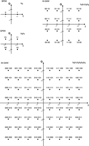
Figure 6-9: BPSK, QPSK, 16-QAM, and 64-QAM constellation bit encoding
PMD Operating Specifications (General) Subclauses 17.3.8.1 through 17.3.8.8 in the standard provide general specifications for the BPSK OFDM, QPSK OFDM, 16-QAM OFDM, and 64-QAM OFDM PMD sublayers. These specifications apply to both the receive and transmit functions and general operation of the OFDM PHY.
Outline Description The general block diagram of the transmitter and receiver for the OFDM PHY is shown in Figure 6-10. Major specifications for the OFDM PHY are listed in Table 6-13.
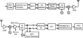
Figure 6-10: Transmitter and receiver block diagram for the OFDM PHY
| Parameter | Value |
|---|---|
| Information data rate | 6, 9, 12, 18, 24, 36, 48, and 54 Mbps (6, 12, and 24 Mbps are mandatory) |
| Modulation | BPSK OFDM QPSK OFDM 16-QAM OFDM 64-QAM OFDM |
| Error correcting code | K = 7 (64 states) convolutional code |
| Coding rate | 1/2, 2/3, 3/4 |
| Number of subcarriers | 52 |
| OFDM symbol duration | 4.0 ms |
| Guard interval | 0.8 µs (TGI) |
| Occupied bandwidth | 16.6 MHz |
Operating Channel Frequencies
Operating Frequency Range The OFDM PHY operates in the 5 GHz band, as allocated by a regulatory body in its operational region. Spectrum allocation in the 5 GHz band is subject to authorities responsible for geographic-specific regulatory domains (global, regional, and national). The particular channelization to be used for this standard is dependent on such allocation as well as the associated regulations for use of the allocations. These regulations are subject to revision or may be superseded. In the United States, the FCC is the agency responsible for the allocation of the 5 GHz U-NII bands.
In some regulatory domains, several frequency bands may be available for OFDM PHY-based wireless LANs. These bands may be contiguous or not, and different regulatory limits may be applicable. A compliant OFDM PHY supports at least one frequency band in at least one regulatory domain.
Channel Numbering Channel center frequencies are defined at every integral multiple of 5 MHz above 5 GHz. The relationship between center frequency and channel number is given by the following equation:
Channel center frequency = 5000 + 5 x nch (MHz)
where nch = 0,1, . . ., 200.
This definition provides a unique numbering system for all channels with 5 MHz spacing from 5 GHz to 6 GHz as well as the flexibility to define channelization sets for all current and future regulatory domains.
Channelization The set of valid operating channel numbers by regulatory domain is defined in Table 6-14.
| Regulatory domain | Band (GHz) | Operating channel numbers | Channel center frequencies (MHz) |
|---|---|---|---|
| United States | U-NII lower band (5.15-5.25) | 36 40 44 48 | 5,180 5,200 5,220 5,240 |
| United States | U-NII middle band (5.25-5.35) | 52 56 60 64 | 5,260 5,280 5,300 5,320 |
| United States | U-NII upper band (5.725-5.825) | 149 153 157 161 | 5,745 5,765 5,785 5,805 |
Figure 6-11 shows the channelization scheme for this standard, which is used with the FCC U-NII frequency allocation. The lower and middle U-NII subbands accommodate eight channels in a total bandwidth of 200 MHz. The upper U-NII band accommodates four channels in a 100 MHz band-width. The centers of the outermost channels are at a distance of 30 MHz from the band's edges for the lower and middle U-NII bands, and 20 MHz for the upper U-NII band. The OFDM PHY operates in the 5 GHz band, as allocated by a regulatory body in its operational region.
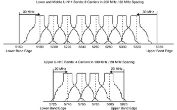
Figure 6-11: OFDM PHY frequency channel plan for the United States
Transmit Power Levels The maximum output power allowable under FCC regulations is shown in Table 6-15.
| Frequency band (GHz) | Maximum output power with up to 6 dBi antenna gain (mW) |
|---|---|
| 5.15-5.25 | 40 (2.5 mW/MHz) |
| 5.25-5.35 | 200 (12.5 mW/MHz) |
| 5.725-5.825 | 800 (50 mW/MHz) |
PLCP Transmit Procedure See Figure 6-12.
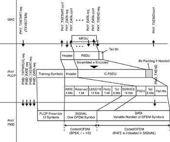
Figure 6-12: PLCP transmit procedure
OFDM PMD Sublayer
Scope and Field of Application This section of the standard describes the PMD services provided to the PLCP for the OFDM PHY. Also defined in this section are the functional, electrical, and RF characteristics required for the interoperability of implementations conforming to this specification (see Table 6-16). The relationship of this specification to the entire OFDM PHY was shown in Figure 6-4.
| Characteristics | Value |
|---|---|
| aSlotTime | 9 ms |
| aSIFSTime | 16 ms |
| aCCATime | < 4 ms |
| aRxTxTurnaroundTime | < 2 ms |
| aAirPropagationTime | << 1 ms |
| aMACProcessingDelay | < 2 ms |
| aPreambleLength | 20 ms |
| aPLCPHeaderLength | 4 ms |
| aMPDUMaxLength | 4,095 |
| aCWmin | 15 |
| aCWmax | 1,023 |
Overview of Service The OFDM PMD sublayer accepts PLCP sublayer service primitives and provides the actual means by which data is transmitted or received from the medium. The combined function of the OFDM PMD sublayer primitives and parameters for the receive function results in a data stream, timing information, and associated received signal parameters being delivered to the PLCP sublayer. A similar functionality is provided for data transmission.
Overview of Interactions The primitives associated with the IEEE 802.11 PLCP sublayer to the OFDM PMD fall into two basic categories (see Figure 6-13):
-
Service primitives that support PLCP peer-to-peer interactions
-
Service primitives that have local significance and support sublayer-tosublayer interactions
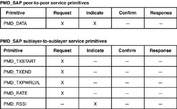
Figure 6-13: Primitives
Example In this section we'll consider an example frame encoded for the OFDM PHY. Encoding goes through the following stages (refer to the standard for a detailed example of the encoding):
-
Generating the short training sequence section of the preamble
-
Generating the long preamble sequence section of the preamble
-
Generating the SIGNAL field bits
-
Coding and interleaving the SIGNAL field bits
-
Mapping the SIGNAL field into a frequency domain
-
Pilot insertion
-
Transforming into a time domain
-
Delineating the data octet stream into a bit stream
-
Prepending the SERVICE field and adding the pad bits, thus forming the DATA
-
Scrambling and zeroing the tail bits
-
Encoding the DATA with a convolutional encoder and puncturing
-
Mapping into complex 16-QAM symbols
-
Pilot insertion
-
Transforming from frequency to time and adding a circular prefix
-
Concatenating the OFDM symbols into a single, time-domain signal
|
|
EAN: N/A
Pages: 88