WWAN Approaches
|
|
This section provides some additional details on WWAN technologies. Up to now, these architectures have focused on voice services or at most low-speed (for example, 9.6 Kbps) circuit-mode data. The plans for the future are to add higher-speed data services. Hotspot networks continue to be best served by WLANs and WPANs for the next two to three years rather than by WWANs.
Current Baseline
As already noted, the major cellular architectures now in place encompass the following:
-
Time Division Multiple Access (TDMA) (IS-136)
-
cdmaOne (see Figure 3-11)
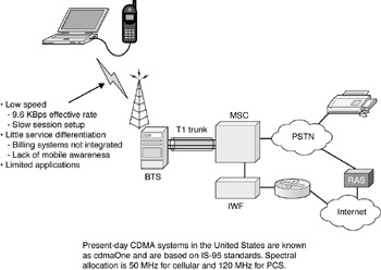
Figure 3-11: Circuit-mode data over cellular phone -
Global System for Mobile Communications (GSM) with General Packet Radio Services (GPRS) (see Figures 3-12 and 3-13)
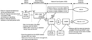
Figure 3-12: GPRS architecture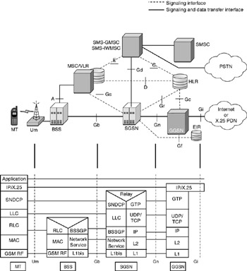
Figure 3-13: GPRS protocol stack
These architectures have rather limited support for data services. Evolving architectures include
-
CDMA2000 Evolving third-generation (3G) in the United States (see Figures 3-14 and 3-15)
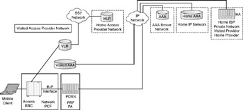
Figure 3-14: CDMA2000 network architecture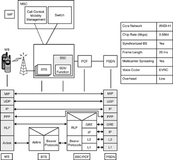
Figure 3-15: CDMA2000 reference model and protocol stack -
Wideband CDMA (W-CDMA) Evolving 3G in the rest of the world
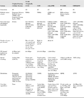
Table 3-5 summarizes some key capabilities of first-generation (1G), second-generation (2G), and 3G WWAN systems.
Table 3-5. Table Key capabilities of 1G, 2G, and 3G systems
Time Division Multiple Access (TDMA)
In the early 1990s, the Telecommunications Industry Association/Electronics Industry Association (TIA/EIA) developed a TDMA standard that became known as IS-54 (1992). Systems based on this technology were introduced in the United States in 1993. This standard was eventually superceded by a newer version called TIA/EIA IS-136.1 and IS-136.2 in 1994. With the standard, a TDMA frame is 40 milliseconds long and consists of six time slots (each, therefore, are 6.67 milliseconds). Three callers can be accommodated in a 30 kHz band. For IS-136, the spectrum allocation is 824 to 849 MHz in the inbound link and 869 to 894 MHz in the outbound link. The approach, therefore, is to use TDMA over each FDMA 30 kHz channel.
cdmaOne
The feasibility of a commercial CDMA-based system based on code division multiplexing techniques that had been used in military communications was demonstrated in 1998. cdmaOne is based on TIA/EIA specifications IS-95A and IS-95B; cellular applications operate at 850 MHz (50 MHz bandwidth) and personal communications service (PCS) applications operate at 1,800 MHz (120 MHz bandwidth). Each caller is assigned a unique pseudonoise (PN) code whose clock rate (that is, the chip rate) is much higher than the user data rate. The PN code modulates the user data and the resulting output phase modulates a carrier. The spectrum is partitioned into a number of channels, each with a bandwidth of 1.25 MHz. CDMA systems have a number of advantages over other systems. They can provide much larger bandwidth per channel, they provide a more robust communication of data services employing efficient channel coding, they make more efficient utilization of the spectrum, and they support better speech quality using low-bit-rate linear predictive coders.
Global System for Mobile Communications (GSM)
GSM was developed in 1990s for European digital cellular communications. GSM-based systems were first deployed in 18 European countries in 1991. By the end of 1993, it was adopted in 9 additional countries of Europe, as well as South America, Australia, and much of Asia. Some deployment also exists in the United States. For example, AT&T Wireless has been converting its network to GSM and the conversion was 60 percent complete by the end of 2002 (the entire network will then run on GSM, though AT&T will keep its older network operational so that customers are not forced to replace their cell phones.) Cingular and VoiceStream also operate on GSM technology. GSM technology is seeing rapid deployment in many parts of the world and is evolving to provide advanced features and data communications. GSM combines FDMA and TDMA access schemes and uses two frequency bands in the 900 MHz area. The reverse link operates at 890 to 915 MHz and the forward link operates at 935 to 960 MHz. Each channel has a bandwidth of 200 kHz and is comprised of eight time slots, each of which is assigned to an individual user.[11] Speech is digitally encoded at 13 Kbps using linear predictive coding (LPC); information is transmitted in frames, which are each 4.615 milliseconds long and divided into eight equal time slots. Table 3-6 identifies the key capabilities of GSM. It supports voice, circuit-switched data, and SMS. MTs can transmit or receive short messages during both idle and active call states. A message can contain up to 160 alphanumeric characters; shorter messages of 93 characters can be broadcast repetitively by a base station to all mobiles in a serving area.
| Service | Features |
|---|---|
| Teleservices | Mobile telephony with interworking with Public Switched Telephone Networks (PSTNs), emergency calling, and voice messaging. |
| Bearer services | Data services and short messaging services. Data services are either circuit mode or packet mode. In circuit-mode data, the Mobile Switching Center (MSC) may be connected to a circuit-switched PSTN via a modem and have speeds up to 9.6 Kbps. In packet-mode data, the MSC is connected to the Internet or a public data network (via a packet assembler/diassembler device [PAD]) and connectivity is supported at 2.4, 4.8, and 9.6 Kbps. Each physical channel is shared by multiple users. Users can request a QoS-based service from the network; however, only a limited number of QoS profiles are supported. |
| Supplementary services | Call forwarding, call hold, call waiting, call transfer, calling number identification, three-party conference calls, and so on. |
GSM supports circuit-switched data services at rates up to 9.6 Kbps (it can support a maximum of 76.8 Kbps data rate by inverse-multiplexing eight channels). The development of standards for providing a packet-mode data service in GSM started in 1994 and was completed in 1997. The new system specified by these standards is called GPRS. GPRS supports a new set of bearer services for GSM. It provides packet-mode transmission within the Public Land Mobile Network (PLMN) environment and allows interworking with Transmission Control Protocol/Internet Protocol (TCP/IP) networks (such as the Internet) and with X.25 networks. GPRS also supports QoS as defined by metrics such as priority (precedence), delay, throughput, and reliability/availability. Table 3-7 depicts the key GPRS protocols and interfaces.
| Interface | Protocol | Notes |
|---|---|---|
| Base station subsystem/mobile terminal (BSS/MT) | Radio Layer Control (RLC) | Defines procedures for the retransmission of unsuccessfully delivered data units |
| MAC | Defines procedures for multiple MTs to share a common transmission link (several MTs on one transmission or one MT to several transmissions) | |
| Gateway GPRS Support Node/Serving GPRS Service Node (GGSN/SGSN) (Gn) | IP/X.25 | Interworks with external data network |
| GPRS Tunneling Protocol (GTP) | Tunnels from/to entry GGSN to/from SGSN supporting the MT | |
| User Datagram Protocol (UDP)/TCP | Transports data and signaling information in the GPRS environment | |
| SGSN/BSS/MT | Subnetwork Data Convergence Protocol(SNDCP) | Supports non-GSM layer 2 services, the compression of headers, and SAR |
| LLC | Supports non-GSM layer 1 services and logical link connections between SGSN and MT | |
| Base Station System GPRS Protocol (BSSGP) | Provisioning at the radio level | |
| Network service | Frame relay |
GPRS aims at making efficient use of valuable air interface resources. In a radio environment, it makes perfect sense to be efficient in transmission; many times designers go out of their way to be super efficient on terabit-per-second optical fiber systems, where it makes no sense to trade bandwidth for complexity - in wireless systems, however, this design criterion is legitimate. GPRS uses excess voice capacity for data transmissions. Unlike standard TDMA systems, with GPRS, radio resources are utilized only when the user is actually sending or receiving data. This approach clearly lowers the cost of data transmission as measured in cost per bit. This also enables the operators to charge fees based on the packets transmitted rather than on air time, if they so choose. This also provides a simpler environment for application development and deployment.
Basic applications include access to the Internet or an intranet. Customers can be given cost-effective access to WAP-based applications. The goal of carriers is to increase the average revenue per user (ARPU). (Vodafone reportedly increased ARPU by 25 percent over five years by offering wireless Internet applications.) Services will be introduced in two phases. Phase 1 will support point-to-point services, interworking with TCP/IP, and X.25 services between the MT and the GGSN (using X.28 between the MT and the GGSN) and between the GGSN and external X.25 networks. Phase 2 is expected to support point-to-multipoint multicast/broadcast services.
Table 3-8 identifies some key elements of today's data WWAN networks. Figure 3-16 shows a typical 2G network, specifically of GSM. The air interface is known as reference point Um; it exists between a mobile station and a base transceiver station (BTS). Each cell is served by a BTS that consists of one or more radio receivers and transmitters. Base station controllers (BSCs) perform radio control functions; this includes power control as received from the mobile station and potential handoff to another cell. Each BSC can connect to one or more BTSs over the A-bis interface. There may be one or more BSCs in a serving area. BTSs and the associated BSCs for a given area are known as a base station subsystem (BSS). (Note that BSS does not stand for basic service set in this context.)
| AuC | Authentication Center-Retains information for the authentication of mobile users and for encrypting the data (and voice) session. |
| BSC | Base station controller-It makes up the guts of a base station. It controls the radio equipment in the BSS. |
| BTS | Base transceiver station-It is the radio portion of the BSS. |
| GMSC | Gateway Mobile Switching Center-Supports switching between the wireline and the wireless networks. |
| HLR | Home Location Register-A system providing subscriber profiles and authorization information in the wireless network. |
| MS | Mobile subscriber |
| MSC | Mobile Switching Center-The (classical) (voicecentric) circuit switch that connects the mobile radio access to the PSTN. |
| SCP | Service control point-The CCSS7 system that contains the information required to complete some kinds of calls (for example, 800/toll free or Advanced Intelligent Network [AIN]). |
| SMS-C | Short Message Service Center-A system to support SMS, which is a globally accepted wireless capability that enables the transmission of messages between MSs and external systems (such as v-mail, e-mail, paging, and so on). |
| VLR | Visitor Location Register-A database that contains temporary information about MSs that is needed by the MSC in order to support visiting subscribers. |
| BSS | Base station subsystem-It includes the BTS and BSC. |
| PSTN | Public Switched Telephone Network-The existing wireline telephone network. |
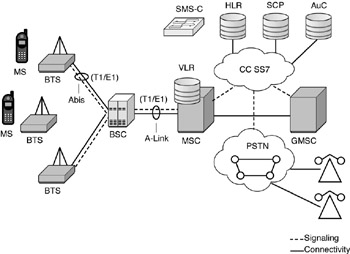
Figure 3-16: Typical 2G network
The MSC is responsible for call controls, call routing to/from PSTNs, call switching, and call handover. The MSC connects to a BSS over the A interface. The MSC interconnects with a number of other systems, namely with the Visitor Location Register (VLR), the Home Location Register (HLR), the Equipment Identity Register (EIR), and the Operations and Maintenance Center (OMC). The MSC also makes use of the Authentication Center (AuC), which is associated with the HLR. The HLR is a database system of all mobile subscribers who are registered in a PLMN. (The HLR may be implemented in a distributed fashion.) The VLR contains the database of all mobile subscribers who are visiting a specified serving area.
Whenever a mobile station roams into a foreign serving area, the VLR[12] of the visited system requests the database of that mobile station from its HLR and saves this information in its memory so that it can serve that mobile as long as it is in that area. At the same time, the MSC of this foreign serving area instructs the HLR of the home system with regards to the location of this mobile station so that the home area of this subscriber can route calls to it when necessary. The AuC authenticates the user at call inception time; the AuC also stores appropriate authentication parameters.
The EIR contains the International Mobile station Equipment Identity (IMEI) numbers of all MSs that are registered. Each mobile station is assigned a unique IMEI number that can be used to determine whether the equipment is legitimate.
The OMC is a centralized network management system that provides the capability of remote system administration and maintenance. The Mobile Application Part (MAP) protocol of Common Channel Signaling System 7 (CCSS7) provides signaling between an MSC, the VLR, the HLR, and the AuC.
GPRS requires two new network elements: an SGSN and GGSN. The SGSN provides GPRS services to a mobile station in the serving area of its associated MSC (when there are multiple SGSNs, they are connected together over an IP-based Gn interface). An SGSN node locates MSs that subscribe to GPRS services and adds this information to the HLR. An SGSN connects to a GGSN via a Gn interface and to its BSS over a Gb interface (this uses a frame relay protocol at layer 2). The GGSN provides an interface between a GPRS network and any external network. The GGSN contains the routing information of all of the mobile stations attached to it and forwards an incoming packet appropriately en route to its destination. In the 2.5G version of the system, GPRS is supported by adding packet-handling capabilities to the BSC. This is done by means of an interface called the packet control unit (PCU). In a 3G system, the interface to a GPRS network is expected to be integrated into the BSS.
Third Generation (3G)
The brief snapshot of 3G technology in this section is based on an exposition of the topic by Zahariadis, Vaxevanakis, Tsantilas, Zervos, from which the following text has been reprinted.[13]
Next-generation mobile/wireless networks are expected to provide a substantially wider and enhanced range of services compared to current WWAN networks. Global convergence, interoperability, and mobility are some of the differentiating factors. Moreover, the inherent IP support will encourage new personalized interactive multimedia services and broadband applications, such as video telephony, videoconferencing, and mobile Internet. Deployment of a global all-IP wireless/mobile network, however, is expected through evolutionary rather than revolutionary steps.
Vendors promote the new profitable IP services that a network will allow, whereas post, telephone, and telegraph (PTT) companies look to maximize the profit and return on investment (ROI) based on existing equipment. As a result, the wireless network infrastructure may be organized in a cell hierarchy based on technology that is either already deployed or still under development, as depicted in Figure 3-17. Starting from the home cell, coverage in private buildings (such as a house or office) or in hotspot locations (such as an airport, train station, or conference center) may be provided by APs. IEEE 802.11, high-performance radio local area network (HIPERLAN), Bluetooth, and HomeRF are alternative technologies that may be deployed. The APs may also provide connectivity in picocells, whereas a combination with pico-GSM or Digital Enhanced Cordless Telecommunications (DECT) can also be considered. Moreover, fixed wireless access via central stations (CSs) and remote stations (RSs) may provide wireless access up to macrocells in suburban areas. Horizontal mobility to MTs that move with different speeds in micro- or macrocells may be provided by utilizing 2G and 2G+ (also known as 2.5G) networks (such as GSM, high-speed circuit-switched data [HSCSD], GPRS, Enhanced Data rates for Global Evolution [EDGE], Cellular Digital Packet Data [CDPD], IS-95, and CDMA). Connectivity and mobility in satellites cells are provided via Geostationary Earth Orbit (GEO), Medium Earth Orbit (MEO), or Low Earth Orbit (LEO), and Fixed Earth Stations (FESs) or mobile satellite terminals (STs).
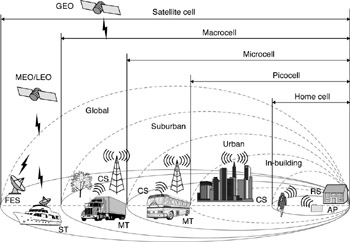
Figure 3-17: Cell hierarchy of a next-generation network
In these environments, roaming is critical. In order to support both horizontal and vertical roaming in such complex environments, the first step is to gain connectivity at the physical layer. In this respect, either multimode or adaptive terminals are considered. For example, terminals equipped with a commercial WLAN (such as IEEE 802.11b), cellular (such as GSM/ GPRS), or satellite network interface cards (NICs) may be introduced. Soft radio techniques have also been proposed. Global roaming, however, requires the integration and interoperation of the mobility management processes of each independent network. IP is the most widely accepted protocol; thus, mobility based on IP will be facilitated by the use of an established technology.
The detailed architecture of an all-IP wireless/mobile network architecture is shown in Figure 3-18. WLAN, 2G and 3G cellular, and satellite networks are selected as alternative radio access networks. Due to different physical and protocol characteristics, each radio access network consists of different base stations and radio control nodes, which are connected to the common core network via a service support node (SSN). This may be an MSC+ for the cellular networks, an IP L1/L2 switch for the WLAN, or an FES. The SSN also provides the VLR or foreign agent (FA) functionality, respectively, in cooperation with an extended HLR+ or home subscriber server (HSS). HSS maintains user profiles and may integrate or cooperate with a Remote Authentication Dial-In User Server (RADIUS) and/or authentication, authorization, and accounting (AAA) server for user authentication and authorization.
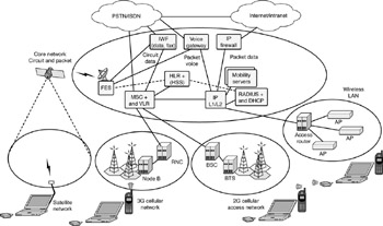
Figure 3-18: An all-IP wireless/mobile network
Interoperability between circuit-switched and packet-based networks is also mandatory; thus, the common core network of the proposed all-IP architecture supports both circuit-based connections and packet-based transmission. Access to both PSTN/Integrated Services Digital Network (PSTN/ISDN) and the Internet is provided via interworking function (IWF) units, voice gateways, firewalls, or generally Gateway Support Nodes (GSNs). Additional servers (such as the Dynamic Host Configuration Protocol [DHCP] and the Domain Name Server [DNS]) provide complementary services in the IP domain, whereas mobility servers provide mapping between Universal Personal Telecommunications (UPT) numbers and dynamic IP addresses.
The architecture is based on enhancements of existing equipment so assume that horizontal roaming will be handled by specific network roaming mechanisms. For example, a direct extension toward roaming of IP traffic in GPRS networks proposed by the GSM Association in the form of a GPRS Roaming Exchange (GRX) architecture that carries traffic between mobile operators' networks. In the vertical roaming scenario, however, the terminal should have a more active role and initiate the specific roaming mechanisms. Starting from the WLAN cell, whenever a terminal is activated, it has to obtain a valid IP address. This may be a preconfigured IP address or most likely a dynamically allocated one via a local or distributed DHCP/DNS server. Moreover, the mobility server responsible for the specific hotspot or AP may authenticate the terminal via a centralized or distributed RADIUS/AAA server.
User/terminal authentication and authorization based on MAC/password pair or Subscriber Identification Module (SIM) card could be considered. The RADIUS+ server communicates with the VLR and/or HLR+ servers and associates the hotspot user with his or her cellular database entry; thus, the user will receive a single bill for all services. After registration and authentication, the user can roam in the hotspot while communicating via the WLAN connection. Moreover, a virtual private network (VPN) can be set up via higher-layer protocols (such as IP security [IPSec] and the Layer 2 Tunneling Protocol [L2TP]), and the MT can access the corporate intranet. When the user moves outside the hotspot coverage area, the terminal has to initiate a vertical roaming mechanism and soft handover to a GSM; a Universal Mobile Telecommunications Service (UMTS) or satellite network can be activated. The mobile network intermediate nodes (node B, RNC in UMTS, BSC, BTS in GSM, and FES in satellite) are considered transparent to mobile Internet traffic because they control radio resources and handover decisions only at the physical level. The terminal communicates with the mobility servers located in the IP part of the network, and a new authentication/authorization process is initialized. After the connection at the physical layer has been established, various Mobile IP extensions may be applied to keep connections uninterrupted.
This topic is revisited in additional detail in Chapter 9, 'Migrating to 3G WWANs.'
[11]GSM operates in the FDD mode, using one band for inbound links and a separate one for outbound links. The 25-MHz spectrum in either direction is partitioned into 125 physical channels, each with a bandwidth of 200 kHz.
[12]There is a VLR for each serving area controlled by an MSC.
[13]T. B. Zahariadis, K. G. Vaxevanakis, C. P. Tsantilas, and N. A., Zervos, 'Global Roaming in Next-Generation Networks,' IEEE Communications Magazine (February 2002): 145 ff.
|
|
EAN: N/A
Pages: 88