Chapter 3: Technologies for Hotspots
|
|
This chapter expands on the discussions of the wireless personal area network (WPAN), wireless local area network (WLAN), and wireless wide area network (WWAN) technology that appeared in Chapter 1, 'Introduction to Wireless Personal Area Networks (WPANs), Public Access Locations (PALs), and Hotspot Services.' This chapter drills down to another level of detail for the major systems that play a role in hotspot networks. It closes with an introduction to antenna technology for hotspot applications.
Wireless Local Area Networks (WLANs)
WLANs can be utilized to replace wired LANs or act as extensions to the wired LAN. 802.11 WLANs support communication between stations and access points (APs) using radio technology that does not require line of sight (LOS) between the AP and station. This technology works well for indoors applications and works fine for controlled outdoors applications. Currently, the Federal Communications Commission (FCC) (and, by extension, most of the regulatory bodies from other countries) allows only two kinds of spread spectrum use: frequency-hopping spread spectrum (FHSS), which is employed by Home Radio Frequency (HomeRF) and Bluetooth, and direct sequence spread spectrum (DSSS), which is used by 802.11b.[1] The radio signal is confined to the 2.4 GHz Industry, Scientific, and Medical (ISM) band.
IEEE 802.11 defines data rates of 1 and 2 Mbps via radio waves using FHSS or DSSS. 802.11b is an enhancement of 802.11 that employs DSSS to achieve a maximum throughput of 11 Mbps.[2] Independent of the data rate (whether it is 1, 2, 5.5, or 11 Mbps), the channel bandwidth for a DSSS system is about 20 MHz; therefore, the ISM band accommodates up to three nonoverlapping channels (see Figure 3-1). The recently defined complimentary code keying (CCK) modulation scheme (IEEE 802.11b) allows speeds of 5.5 and 11 Mbps in the same bandwidth as the original 1 and 2 Mbps DSSS radios. CCK is backward compatible. Table 3-1, which is based directly on the IEEE 802.11 standard, describes key concepts that are applicable to WLANs.
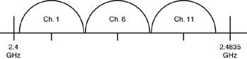
Figure 3-1: Nonoverlapping channels
| Term | Definition |
|---|---|
| Access control | The prevention of unauthorized usage of resources. |
| Access point (AP) | Any entity that has station functionality and provides access to the distribution services via the wireless medium (WM) for associated stations. |
| Ad hoc network | A network composed solely of stations within the mutual communication range of each other via the WM. An ad hoc network is typically created in a spontaneous manner. The principal distinguishing characteristic of an ad hoc network is its limited temporal and spatial extent. These limitations enable the act of creating and dissolving the ad hoc network to be sufficiently straightforward and convenient so as to be achievable by nontechnical users of the network facilities; that is, no specialized technical skills are required and little or no time or additional resources are required beyond the stations that are to participate in the ad hoc network. The term ad hoc is often used to refer to an IBSS. |
| Association | The service used to establish AP/station mapping and enable the station invocation of the distribution system services (DSSs). |
| Authentication | The service used to establish the identity of one station as a member of the set of stations authorized to associate with another station. |
| Basic service area (BSA) | The conceptual area within which members of a BSS may communicate. |
| Basic service set (BSS) | A set of stations controlled by a single coordination function. |
| BSS basic rate set | The set of data transfer rates that all the stations in a BSS will be capable of using to receive frames from the WM. The BSS basic rate set data rates are preset for all stations in the BSS. |
| Broadcast address | A unique multicast address that specifies all stations. |
| Channel | An instance of medium use for the purpose of passing protocol data units (PDUs) that may be used simultaneously in the same volume of space with other instances of medium use (on other channels) by other instances of the same physical layer (PHY). It has an acceptably low frame error ratio due to mutual interference. |
| Clear channel assessment (CCA) function | The logical function in PHY that determines the current state of the WM. |
| Confidentiality | The property of information that is not made available or disclosed to unauthorized individuals, entities, or processes. |
| Coordination function | The logical function that determines when a station operating within a BSS is permitted to transmit and receive PDUs via the WM. The coordination function within a BSS may have one point coordination function (PCF) and will have one distributed coordination function (DCF). |
| Coordination function pollable | A station able to respond to a coordination function poll with a data frame, if such a frame is queued and able to be generated and interpret acknowledgments in frames sent to or from the point coordinator. |
| Deauthentication | The service that voids an existing authentication relationship. |
| Disassociation | The service that removes an existing association. |
| Distributed coordination function (DCF) | A class of coordination function where the same coordination function logic is active in every station in the BSS whenever the network is in operation. |
| Distribution | The service that, by using association information, delivers Medium Access Control (MAC) service data units (MSDUs) within the DS. |
| Distribution system (DS) | A system used to interconnect a set of BSSs and integrated LANs to create an ESS. |
| Distribution system medium (DSM) | The medium or set of media used by a DS for communications between APs and portals of an ESS. |
| Distribution system service (DSS) | The set of services provided by the DS that enable the MAC to transport MSDUs between stations that are not in direct communication with each other over a single instance of the WM. These services include the transport of MSDUs between the APs of BSSs within an ESS, the transport of MSDUs between portals and BSSs within an ESS, and the transport of MSDUs between stations in the same BSS in cases where the MSDU has a multicast or broadcast destination address or where the destination is an individual address, but the station sending the MSDU chooses to involve DSS. DSSs are provided between pairs of IEEE 802.11 MACs. |
| Extended rate set (ERS) | The set of data transfer rates supported by a station (if any) beyond the ESS) basic rate set. This set may include data transfer rates that will be defined in future PHY standards. |
| Extended service area (ESA) | The conceptual area within which members of an ESS may communicate. An ESA is larger than or equal to a BSA and may involve several BSSs in overlapping, disjointed, or both configurations. |
| Extended service set (ESS) | A set of one or more interconnected BSSs and integrated LANs that appears as a single BSS to the Logical Link Control (LLC) layer at any station associated with one of those BSSs. |
| Gaussian frequency shift keying (GFSK) | A modulation scheme in which the data is first filtered by a Gaussian filter in the baseband and then modulated with a simple frequency modulation. |
| Independent basic service set (IBSS) | A BSS that forms a self-contained network and in which no access to a DS is available. |
| Infrastructure | The infrastructure includes the DSM, AP, and portal entities. It is also the logical location of distribution and integration service functions of an ESS. An infrastructure contains one or more APs and zero or more portals in addition to the DS. |
| Integration | The service that enables the delivery of MSDUs between the DS and an existing, non-IEEE 802.11 LAN (via a portal). |
| MAC management protocol data unit (MMPDU) | The unit of data exchanged between two peer MAC entities to implement the MAC management protocol. |
| MAC protocol data unit (MPDU) | The unit of data exchanged between two peer MAC entities using the services of the PHY. |
| MAC service data unit (MSDU) | Information that is delivered as a unit between MAC service access points (SAPs). |
| Minimally conformant network | An IEEE 802.11 network in which two stations in a single BSA are conformant with ISO/IEC 8802-11: 1999. |
| Mobile station | A type of station that uses network communications while in motion. |
| Multicast | A MAC address that has the group bit set. A multicast MSDU has a multicast destination address. A multicast MPDU or control frame has a multicast receiver address. |
| Network allocation vector (NAV) | An indicator, maintained by each station, of time periods when transmission onto the WM will not be initiated by the station whether or not the station's CCA function senses that the WM is busy. |
| Point coordination function (PCF) | A class of possible coordination functions in which the coordination function logic is active in only one station in a BSS at any given time that the network is in operation. PCF is an optional extension to DCF. For example, it can provide a time-division capability to accommodate time-bounded, connection-oriented services such as cordless telephony. |
| Portable station | A type of station that may be moved from location to location, but that only uses network communications while at a fixed location. |
| Portal | The logical point at which MSDUs from a non-IEEE 802.11 LAN enter the DS of an ESS. |
| Privacy | The service used to prevent the content of messages from being read by someone other than the intended recipient. |
| Reassociation | The service that enables an established association (between the AP and station) to be transferred from one AP to another (or the same) AP. |
| Station | Any device that contains an IEEE 802.11 conformant MAC and PHY interface to the WM. |
| Station basic rate | A data transfer rate belonging to the ESS basic rate set that is used by a station for specific transmissions. The station basic rate may change dynamically as frequently as a search MPDU transmission attempt based on local considerations at that station. |
| Station service (SS) | The set of services that support the transport of MSDUs between stations within a BSS. |
| Time unit (TU) | A measurement of time equal to 1,024 ms. |
| Unauthorized disclosure | The process of making information available to unauthorized individuals, entities, or processes. |
| Unauthorized resource use | The use of a resource that is not consistent with the defined security policy. |
| Unicast frame | A frame that is addressed to a single recipient, not a broadcast or multicast frame. |
| Wired Equivalent Privacy (WEP) | The optional cryptographic confidentiality algorithm specified by IEEE 802.11 used to provide data confidentiality that is subjectively equivalent to the confidentiality of a wired LAN medium that does not employ cryptographic techniques to enhance privacy. |
| Wireless medium (WM) | The medium used to implement the transfer of PDUs between peer PHY entities of a WLAN. |
Figure 3-2 depicts the basic topology of an IEEE 802.11 environment. A basic service set (BSS) consists of two or more wireless stations that have recognized each other and have established communications. Within a given cell coverage area, stations communicate directly with each other on a peer-to-peer basis; this type of network is usually established on a temporary timeframe and is commonly referred to as an ad hoc network or an independent basic service set (IBSS). More typically, the BSS contains an AP. The AP operates as a bridge between the wireless and wired LAN. APs are fixed-location network elements and are considered part of the wired network infrastructure. When an AP is present, the stations do not communicate on a peer-to-peer basis, but communicate through the AP instead. A BSS with APs is said to be operating in the infrastructure mode. All station clocks within a BSS are synchronized by the periodic transmission of timestamped beacons. Beacons are used to convey network parameters such as hop sequence. Probe requests and responses are utilized to join a network.
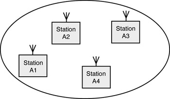
Figure 3-2: IBSS
There are two power-saving modes defined for stations: awake and doze. In the awake mode, stations can receive packets at any time. In the doze mode, stations must 'wake up' periodically to listen for beacons that indicate that the AP has queued messages. Stations must inform the AP before entering the doze state.
Figure 3-3 depicts an extended service set (ESS). The ESS consists of a group of overlapping BSSs (each containing an AP) connected together via a distribution system (DS). Although the DS can be any type of network, it is often an Ethernet LAN. Mobile stations can roam between APs and seamless coverage is maintained. The IEEE standard identifies the basic message formats to support roaming, but the details are left up to network vendors.
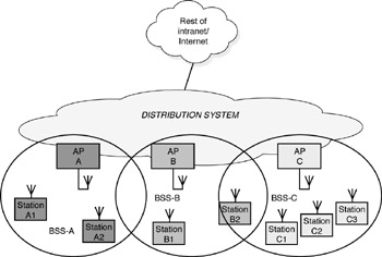
Figure 3-3: ESS
802.11 uses carrier sense multiple access/collision avoidance (CSMA/ CA). Although 802.3 uses carrier sense multiple access/collision detection (CSMA/CD), which has a 100 percent collision-detect mechanism to support reliable data transfer, the CA apparatus is better optimized to an environment where there are large differences in signal strengths. With CA, collisions can only be inferred after the fact. The transmitter fails to get a response and the receiver sees corrupted information via the cyclic redundancy check (CRC). This topic is revisited later in the section 'Multiple Access.'
Multipath fading can inhibit signal reception. Multiple antennas can be used to minimize this problem via spatial separation of orthogonality. This is called antenna diversity.
Wireless PHYs
Spread Spectrum Most WLAN systems[3] use spread spectrum technology, a wideband radio frequency (RF) technique developed by the military for use in reliable, secure, mission-critical communications systems. Some PHYs provide only one channel, whereas others provide multiple channels; examples of channel types are shown in Table 3-2.
| Single Channel | n-channel |
|---|---|
| Narrowband RF channel | Frequency division multiplexed channels |
| Baseband infrared (IR) | DSSS with Code Division Multiple Access (CDMA) |
Spread spectrum is designed to trade off bandwidth efficiency for reliability, integrity, and security. That is, more bandwidth is consumed than in the case of narrowband transmission, but the trade-off produces a signal that is easier to detect, provided that the receiver knows the parameters of the spread spectrum signal being broadcast. If a receiver is not tuned to the correct frequency, a spread spectrum signal looks like background noise. As noted previously, there are two types of spread spectrum radio: FHSS and DSSS.
FHSS Technology A narrowband radio system transmits and receives user information on a specific RF. Narrowband radio keeps the radio signal frequency as narrow as possible just to pass the information. Undesirable crosstalk between communications channels is avoided by coordinating different users on different channel frequencies. In a radio system, privacy and noninterference are accomplished by the use of separate radio frequencies. The radio receiver filters out all radio signals except the ones on its designated frequency. FHSS uses a narrowband carrier that changes frequency in a pattern known to both the transmitter and receiver. Properly synchronized, the net effect is to maintain a single logical channel. To an unintended receiver, FHSS appears to be short-duration impulse noise (see Figure 3-4).
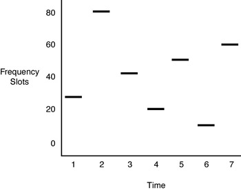
Figure 3-4: FHSS
DHSS Technology DHSS generates a redundant bit pattern for each bit to be transmitted. This bit pattern is called a chip (or chipping code). The longer the chip, the greater the probability that the original data can be recovered (and, of course, the more bandwidth is required). Even if one or more bits in the chip are damaged during transmission, statistical techniques embedded in the radio can recover the original data without the need for retransmission. To an unintended receiver, DSSS appears as low-power wideband noise and is ignored by most narrowband receivers (see Figure 3-5).
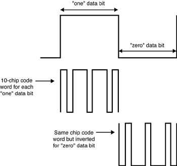
Figure 3-5: DSSS
In a DSSS system, each information bit is combined via an exclusive OR (XOR) function with a longer pseudorandom numerical sequence. The result is a high-speed digital stream that is then modulated onto a carrier frequency using differential phase-shift keying (DPSK). Receive-end electronics remove the PN sequence and recover the original data stream. The high-rate modulation method is called CCK. The effects of using pseudorandom numerical sequence codes to generate the spread spectrum signal are shown in Figure 3-6.[4] As illustrated in Figure 3-6a, the pseudorandom numerical sequence spreads the transmitted bandwidth of the signal and reduces the peak power. (Note, however, that the total power is unchanged.) Upon reception, the signal is correlated with the same pseudorandom numerical sequence to reject narrowband interference and recover the original binary data (see Figure 3-6b).
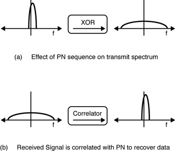
Figure 3-6: DSSS signal operation
Infrared (IR) Technology IEEE 802.11 also specifies an IR PHY. IR systems use very high frequencies just below visible light in the electromagnetic spectrum to carry data. Like light, IR cannot penetrate opaque objects; it is either directed (LOS) or diffuse technology. Inexpensive directed systems provide very limited range (three feet) and are typically used for PANs, but occasionally are used in specific WLAN applications. High-performance directed IR is impractical for mobile users and is therefore used only to implement fixed subnetworks. Diffuse (or reflective) IR WLAN systems do not require LOS, but cells are limited to individual rooms.
Multiple Access
The 802.11 MAC layer is based on two methods: the DCF for asynchronous contention-based access and the PCF for centralized contention-free access. The former is considered to be the default access mechanism; the latter is an optional function envisaged to support collision-free and time-bounded services.[5] DCF permits automatic medium sharing between compatible PHYs through the use of CSMA/CA and a random backoff time following a busy medium condition. In addition, all directed traffic uses an immediate positive acknowledgment (ACK) frame where retransmission is scheduled by the sender if no ACK is received.[6]
The CSMA/CA protocol is designed to reduce the collision probability between multiple stations accessing a medium at the point where collisions would most likely occur. Just after the medium becomes idle following a busy medium (as indicated by the Carrier Sense [CS] function) is when the highest probability of a collision exists. This is because multiple stations could have been waiting for the medium to become available again. This situation necessitates a random backoff procedure to resolve medium contention conflicts.
CSMA/CA mechanisms rely on physical carrier sense; namely, the underlying assumption is that each station can hear all other stations. CSMA/CA requires each station to listen for other users. If the channel is idle, the station is allowed to transmit; if the channel is busy, each station must wait until transmission stops and then can enter into a backoff procedure. The backoff randomization procedure prevents multiple stations from seizing the medium immediately after completion of the preceding transmission. Packet reception requires an acknowledgement procedure that entails the transmission of ACK frames (these frames have a higher priority than other traffic). The time interval between the completion of packet transmission and the transmission of the ACK frame is one short interframe space (SIFS). See Figure 3-7.
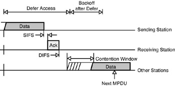
Figure 3-7: DCF procedure
Data frame transmissions (other than ACKs) can occur only after at least one DCF interframe space (DIFS). More specifically, if a transmitting station senses a busy channel, it determines a random backoff period. The timer is an integer number of slot times beyond the expiration of a DIFS; that is, the timer begins to decrement after one DIFS. When the timer reaches zero, the station may begin transmission. Note that if the channel is seized by another station before the timer at the station in question reaches zero, the timer is retained at the current decremented value for a subsequent transmission.
There are situations where every station cannot hear all other stations. In this hidden node situation, the probability of collision has significantly increased. To address this issue, an additional carrier sense mechanism is available. The virtual carrier sense mechanism enables a station to reserve the channel for a specified period of time through the use of Request to Send/Clear to Send (RTS/CTS) frames. Here, Station 1 (STA-1) sends an RTS frame to the AP, but the RTS is not heard by Station 2 (STA-2). The RTS frame contains a Duration/ID field that specifies the period of time that the channel is reserved for a follow-on transmission. The reservation information is maintained in the NAV of all stations receiving the RTS frame. When the AP receives an RTS, it responds with a CTS frame that also contains a Duration/ID field that specifies the period of time for which the channel is reserved. Although STA-2 did not receive the original RTS, it will be able to receive the CTS and update its NAV.
The RTS/CTS procedure is invoked based on a user-specified parameter. The procedure can always be used, never be used, or be used for packets that exceed a defined length. The RTS/CTS mechanism need not be used for every data frame transmission. Because the additional RTS and CTS frames add overhead inefficiency, the mechanism is not always justified, especially for short data frames.
Therefore, the virtual carrier sense mechanism is achieved by distributing reservation information announcing the impending use of the medium. The exchange of RTS and CTS frames prior to the actual data frame is one means of distributing this medium reservation information. The RTS and CTS frames contain a Duration/ID field, which defines the period of time that the medium is to be reserved to transmit the actual data frame and returning ACK frame. All stations within the reception range of either the originating station (which transmits the RTS) or the destination station (which transmits the CTS) can learn about the medium reservation. Thus, a station may be unable to receive from the originating station, yet it still knows about the impending use of the medium to transmit a data frame.
Another means of distributing the medium reservation information is the Duration/ID field in directed frames. This field gives the time that the medium is reserved, either to the end of the immediately following ACK or, in the case of a fragment sequence, to the end of the ACK following the next fragment.[6]
The RTS/CTS exchange also performs a type of fast collision inference and transmission path check. If the return CTS is not detected by the stations originating the RTS, the originating station may repeat the process (after observing the other medium-use rules) more quickly than if the long data frame had been transmitted and a return ACK frame had not been detected. Another advantage of the RTS/CTS mechanism can be found where multiple BSSs utilize the same channel overlap. The medium reservation mechanism works across the BSA boundaries. The RTS/CTS mechanism may also improve operation in a typical situation where all stations can receive from the AP, but cannot receive from all other stations in the BSA. The RTS/CTS mechanism cannot be used for MPDUs with broadcast and multicast immediate addresses because there are multiple destinations for the RTS and thus potentially multiple concurrent senders of the CTS in response.
The nominal peak throughput offered to the Internet Protocol (IP) layer for a maximum transmission unit (MTU) of 1,500 bytes is shown in Table 3-3 for four IEEE 802.11/11b rates.5 As the table indicates, 44 percent signaling rate consumption is encountered when 11 Mbps is used, mainly due to the overhead of the preamble and physical header in IEEE 802.11, which appears quite large in relation to the payload transmission time. In order to guarantee compatibility with lower rates, these 24 bytes of PHY preamble and header overhead have to be transmitted at 1 Mbps for the four supported rates, which consumes 192 ms for each data or acknowledgment frame. Because this overhead is constant for every data packet transmitted, the loss in throughput efficiency becomes more pronounced with shorter data packets. It has been recommended to implement the short preamble and header (which lasts only half as long as the long one) defined as an optional feature within the standard.[7]
| Bit Rate (Mbps) | Nominal Throughput (Mbps) | Bit Rate (%) |
|---|---|---|
| 11 | 6.2 | 56 |
| 5.5 | 3.9 | 71 |
| 2 | 1.7 | 85 |
| 1 | 0.9 | 90 |
Since the IEEE 802.11b specification was finalized in 1999, the 802.11 Work Group is also developing other specifications such as 802.11a for data rates up to 54 Mbps (using orthogonal frequency division multiplexing [OFDM] at the 5 GHz band) and 802.11e for quality of service (QoS) and multimedia traffic support. In particular, the aim of these last specifications is to add some new traffic management policies and error control mechanisms (such as forward error correction [FEC] and selective retransmission) to the high-rate extensions of the 802.11 standard.
IEEE 802.11 provides for security via two methods: authentication and encryption. Authentication is the mechanism by which one station is verified to have authorization to communicate with a second station in a given coverage area; in the infrastructure mode, authentication is established between an AP and each station. IEEE 802.11 defines two subtypes of authentication service: open system and shared key. The subtype invoked is indicated in the body of authentication management frames. Therefore, authentication frames are self-identifying with respect to the authentication algorithm. All management frames of subtype authentication are unicast frames as authentication is performed between pairs of stations (that is, multicast authentication is not allowed). Management frames of subtype deauthentication are advisory and may, therefore, be sent as group-addressed frames.
A mutual authentication relationship exists between two stations following a successful authentication exchange. Authentication is used between stations and the AP in an infrastructure BSS. Authentication may be used between two stations in an IBSS. In an open system, any station may request authentication. The station receiving the request may grant authentication to any request or only those from stations on a user-defined list. In a shared key system, only stations that possess a secret encrypted key can be authenticated. Shared key authentication is only available to systems having the optional encryption capability.
Next we discuss encryption. Eavesdropping is a familiar problem that users of other types of wireless technology face. IEEE 802.11 specifies a WEP data confidentiality algorithm. WEP was designed to protect authorized users of a WLAN from casual eavesdropping. This service is intended to provide functionality for the WLAN that is equivalent to that provided by the physical security attributes inherent to a wired medium. Data confidentiality depends on an external key management service to distribute data enciphering/deciphering keys. The IEEE 802.11 standards committee specifically discourages running an IEEE 802.11 LAN with privacy but without authentication. Although this combination is possible, it leaves the system open to significant security threats. Encryption (see Figure 3-8) is intended to provide integrity and confidentiality.
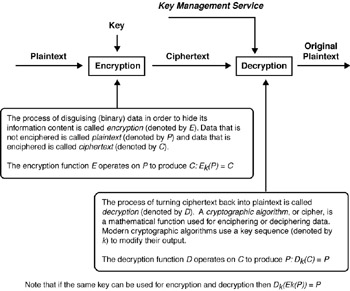
Figure 3-8: Basics of encryption
The following section is reprinted material from the ANSI/IEEE 802.11 standard, 1999 Edition.[6]
The WEP feature uses the Ron's Code 4 Pseudorandom Number Generator (RC4 PRNG) algorithm from RSA Data Security, Inc. The description that follows is based directly on the IEEE 802.11 specification. Viewing from left to right in Figure 3-9, enciphering begins with a secret key that has been distributed to cooperating stations by an external key management service. WEP is a symmetric algorithm in which the same key is used for coding and decoding. The secret key is concatenated with an initialization vector (IV) and the resulting seed is input to a PRNG. The PRNG outputs a key sequence k of pseudorandom octets equal in length to the number of data octets that are to be transmitted in the expanded MPDU plus four (because the key sequence is used to protect the integrity check value [ICV] as well as the data). Two processes are applied to the plaintext MPDU. To protect against unauthorized data modification, an integrity algorithm operates on the plaintext P to produce an ICV.
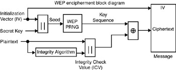
Figure 3-9: WEP
Enciphering is then accomplished by mathematically combining the key sequence with the plaintext concatenated with the ICV. The output of the process is a message containing the IV and ciphertext. The WEP PRNG is the key component of this process because it transforms a relatively short secret key into an arbitrarily long key sequence. This simplifies the task of key distribution as only the secret key needs to be communicated between stations. The IV extends the useful lifetime of the secret key and provides the self-synchronous property of the algorithm. The secret key remains constant while the IV changes periodically. Each new IV results in a new seed and key sequence; thus, there is a one-to-one correspondence between the IV and k. The IV may be changed as frequently as every MPDU and because it travels with the message, the receiver will always be able to decipher any message. The IV is transmitted in the clear because it does not provide an attacker with any information about the secret key and its value must be known by the recipient in order to perform the decryption.
When choosing how often to change IV values, implementers should consider that the contents of some fields in higher-layer protocol headers as well as certain other higher-layer information are constant or highly predictable. When such information is transmitted while encrypting with a particular key and IV, an eavesdropper can readily determine portions of the key sequence generated by that (key, IV) pair. If the same (key, IV) pair is used for successive MPDUs, it may substantially reduce the degree of privacy conferred by the WEP algorithm, enabling an eavesdropper to recover a subset of the user data without any knowledge of the secret key.
Changing the IV after each MPDU is a simple method of preserving the effectiveness of WEP in this situation. The WEP algorithm is applied to the frame body of an MPDU. The (IV, frame body, ICV) triplet forms the actual data to be sent in the data frame. For WEP-protected frames, the first four octets of the frame body contain the IV field for the MPDU. The PRNG seed is 64 bits. Bits 0 through 23 of the IV correspond to bits 0 through 23 of the PRNG seed, respectively. Bits 0 through 39 of the secret key correspond to bits 24 through 63 of the PRNG seed, respectively. The numbering of the octets of the PRNG seed corresponds to that of the RC4 key. The IV is followed by the MPDU, which is followed by the ICV. The WEP ICV is 32 bits. The WEP integrity check algorithm is CRC-32. As stated previously, WEP combines k with P using bitwise XOR.
As noted in Chapter 1, WEP has been found to have holes. Chapter 4, 'Security Considerations for Hotspot Services,' will explore the solutions available to control them.
[1]Glenn Fleishman, 'New Wireless Standards Challenge 802.11b,' www.oreillynet.com/pub/a/wireless/2001/05/08/standards.html, June 8, 2001.
[2]Princy C. Mehta, 'Wired Equivalent Privacy Vulnerability,' http://rr.sans.org/wireless/equiv.php, April 4, 2001.
[3]Material for this subsection has been reprinted from promotional information from Wireless LAN Association (www.wlana.com/learn/ educate1.htm). The Wireless LAN Association is a nonprofit educational trade association comprised of the thought leaders and technology innovators in the local area wireless technology industry. Through the vast knowledge and experience of sponsor and affiliate members, WLANA provides a clearinghouse of information about wireless local area applications, issues, and trends, and serves as a resource to customers and prospects of wireless local area products and wireless personal area products and to industry press and analysts.
[4]Jim Zyren and Al Petrick, 'IEEE 802.11 Tutorial,' www.wirelessethernet.org/downloads/IEEE_80211_Primer.pdf.
[5]L. Munoz, M. Garcia, J. Choque, R. Aguero, and P. Mahonen, 'Optimizing Internet Flows over IEEE 802.11b Wireless Local Area Networks: A Performance-Enhancing Proxy Based on Forward Error Correction,' IEEE Communications Magazine (December 2001): 60 ff.
[6]ANSI/IEEE 802.11 Standard, 1999 Edition [ISO/IEC 8802-11: 1999].
[7]M. G. Arranz et al., 'Behavior of UDP-Based Applications over IEEE 802.11 Wireless Networks,' 12th IEEE International Symposium on Personal Indoor and Mobile Radio Communication, San Diego, September 2001.
[6]ANSI/IEEE 802.11 Standard, 1999 Edition [ISO/IEC 8802-11: 1999].
|
|
EAN: N/A
Pages: 88
- Chapter IV How Consumers Think About Interactive Aspects of Web Advertising
- Chapter XI User Satisfaction with Web Portals: An Empirical Study
- Chapter XIII Shopping Agent Web Sites: A Comparative Shopping Environment
- Chapter XIV Product Catalog and Shopping Cart Effective Design
- Chapter XVII Internet Markets and E-Loyalty