Rendering Animated Meshes

What you want to do now is to render your animated character. The rendering method itself appears deceptively simple, so add the code from Listing 13.8 to your class now.

Listing 13.8 Rendering Your Animated Character
 protected override void OnPaint(System.Windows.Forms.PaintEventArgs e) {     ProcessNextFrame();     device.Clear(ClearFlags.Target | ClearFlags.ZBuffer,         Color.CornflowerBlue, 1.0f, 0);     device.BeginScene();     // Draw our root frame     DrawFrame((FrameDerived)rootFrame.FrameHierarchy);     device.EndScene();     device.Present();     this.Invalidate(); } 

As you can see, the method is quite simple. Process the next frame, clear the device, draw the root frame, and you're done. A lot of things need to happen in these steps, though. First, look at the things that need to be done to process the next frame:

 private void ProcessNextFrame() {     // Get the current elapsed time     elapsedTime = DXUtil.Timer(DirectXTimer.GetElapsedTime);     // Set the world matrix     Matrix worldMatrix = Matrix.Translation(objectCenter);     device.Transform.World = worldMatrix;     if (rootFrame.AnimationController != null)         rootFrame.AnimationController.AdvanceTime(elapsedTime, null);     UpdateFrameMatrices((FrameDerived)rootFrame.FrameHierarchy, worldMatrix); } 

First, the current elapsed time is stored. Next, the world matrix for the root frame is created. Simply translate to the object's center, and update the device. Assuming this mesh has animation, you should advance the time, using the stored elapsed time. Finally, each of combined transformation matrices needs to be updated. Look at the following method:

 private void UpdateFrameMatrices(FrameDerived frame, Matrix parentMatrix) {     frame.CombinedTransformationMatrix = frame.TransformationMatrix *         parentMatrix;     if (frame.FrameSibling != null)     {         UpdateFrameMatrices((FrameDerived)frame.FrameSibling, parentMatrix);     }     if (frame.FrameFirstChild != null)     {         UpdateFrameMatrices((FrameDerived)frame.FrameFirstChild,             frame.CombinedTransformationMatrix);     } } 

In this method, the current frame's combined transformation matrix is calculated by multiplying the frame's transformation matrix along with its parent's transformation matrix. Each of the siblings uses the same parent matrix that the current frame does. Each of the children should use the current frames combined transformation matrix to combine with their own. This forms a "chain" of matrices where the final child has its own transformation matrix, combined with each of its parents.

The next frame has been processed, so now you can actually draw it. The DrawFrame method is actually quite simple, and should look at least somewhat familiar:

 private void DrawFrame(FrameDerived frame) {     MeshContainerDerived mesh = (MeshContainerDerived)frame.MeshContainer;     while(mesh != null)     {         DrawMeshContainer(mesh, frame);         mesh = (MeshContainerDerived)mesh.NextContainer;     }     if (frame.FrameSibling != null)     {         DrawFrame((FrameDerived)frame.FrameSibling);     }     if (frame.FrameFirstChild != null)     {         DrawFrame((FrameDerived)frame.FrameFirstChild);     } } 

You simply walk the tree like normal, only this time, you will attempt to draw every mesh container the frame has a reference to. This method is where the bulk of the work will take place. Use Listing 13.9 to add this method to your application.

Listing 13.9 Rendering a Mesh Container
 private void DrawMeshContainer(MeshContainerDerived mesh, FrameDerived frame) {     // Is there skin information?     if (mesh.SkinInformation != null)     {         int attribIdPrev = -1;         // Draw         for (int iattrib = 0; iattrib < mesh.NumberAttributes; iattrib++)         {             int numBlend = 0;             BoneCombination[] bones = mesh.GetBones();             for (int i = 0; i < mesh.NumberInfluences; i++)             {                 if (bones[iattrib].BoneId[i] != -1)                 {                     numBlend = i;                 }             }             if (device.DeviceCaps.MaxVertexBlendMatrices >= numBlend + 1)             {                 // first calculate the world matrices for the current set of                 // blend weights and get the accurate count of the number of                 // blends                 Matrix[] offsetMatrices = mesh.GetOffsetMatrices();                 FrameDerived[] frameMatrices = mesh.GetFrames();                 for (int i = 0; i < mesh.NumberInfluences; i++)                 {                     int matrixIndex = bones[iattrib].BoneId[i];                     if (matrixIndex != -1)                     {                         Matrix tempMatrix = offsetMatrices[matrixIndex] *                             frameMatrices[matrixIndex].                             CombinedTransformationMatrix;                         device.Transform.SetWorldMatrixByIndex(i, tempMatrix);                     }                 }                 device.RenderState.VertexBlend = (VertexBlend)numBlend;                 // lookup the material used for this subset of faces                 if ((attribIdPrev != bones[iattrib].AttribId) ||                     (attribIdPrev == -1))                 {                     device.Material = mesh.GetMaterials()[                         bones[iattrib].AttribId].Material3D;                     device.SetTexture(0, mesh.GetTextures()[                         bones[iattrib].AttribId]);                      attribIdPrev = bones[iattrib].AttribId;                 }                 mesh.MeshData.Mesh.DrawSubset(iattrib);             }         }     }     else // standard mesh, just draw it after setting material properties     {         device.Transform.World = frame.CombinedTransformationMatrix;         ExtendedMaterial[] mtrl = mesh.GetMaterials();         for (int iMaterial = 0; iMaterial < mtrl.Length; iMaterial++)         {             device.Material = mtrl[iMaterial].Material3D;             device.SetTexture(0, mesh.GetTextures()[iMaterial]);             mesh.MeshData.Mesh.DrawSubset(iMaterial);         }     } } 

This method looks at least somewhat intimidating. Once it's broken down, though, you'll see it really isn't that complicated. First, the skin information member is checked. If this mesh container has no skeletal information, the mesh will be rendered exactly like our meshes have been in the past. If there is skeletal information, however, the rendering path is much different.

USING ANIMATED MESHES WITH NO SKELETON

Just because a mesh has no skeletal information does not mean the mesh has no animation. If the only animation included in the mesh is a standard matrix operation (for example, scale, translate, or rotate), there is no need for any bones or skeleton. However, the animation system will still update the matrices for your mesh, so rendering them like normal will still produce the desired results.

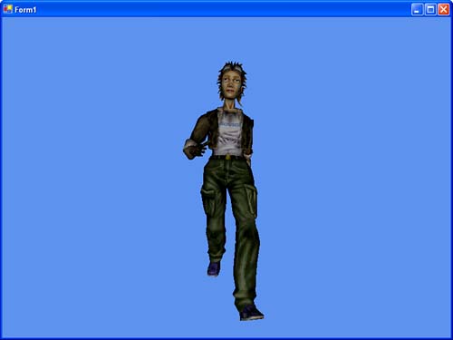
For every attribute entry (set of materials, textures, and so on) in this mesh, a number of operations will need to be performed. First, you must scan through the bone combination table and determine the number of blend weights the mesh will use. The file being used in the example on the included CD uses a maximum of four blend weights, which is what the device creation tests against; however, this code still ensures that the device has the capabilities to blend this many matrices, in case the mesh file has been changed.

Once you've determined that your device can render your mesh with these blend weights, you will need to set the world transforms. For each item you find in the bone id member of your bone combination table, you will combine the offset matrix with the frames combined transformation matrix and set the currently indexed world matrix transform to this resulting matrix. This will allow Direct3D to render each blended vertex with the appropriate world transforms.

Once that's been completed, you set the vertex blend render state to the number of blends this mesh expects. Finally, you set the material and texture of this subset and draw it.

With that, you are ready to run the application. You should expect to see a model walking toward you. See Figure 13.1.

Figure 13.1. An animated mesh.

graphics/13fig01.jpg

SHOP TALK: USING AN INDEXED MESH TO ANIMATE THE BONES

We talked earlier about how rendering vertex data with an index buffer could improve performance by reducing the number of triangles that need to be drawn, and the memory consumption of the triangles already there. In complex characters such as the one being rendered here, the performance benefits of using an indexed mesh are quite noticeable. On top of that, the code is a little shorter as well.

Before you can update the mesh to be an indexed mesh, you will need to make a few changes elsewhere. First, you'll need to add a new member to your derived mesh container class:

 private int numPal = 0; public int NumberPaletteEntries {     get { return numPal; } set { numPal = value; } } 

This will store the number of bone matrices that can be used for matrix palette skinning when we convert our mesh. Next, since we will no longer be using standard vertex blending for our animation, you will need to update the initialization method that ensures your device has this support. Instead, replace that check, with this one:

 if (hardware.MaxVertexBlendMatrixIndex >= 12) 

All that's required now is to replace the generate mesh call (to generate our indexed mesh instead), and then the actual drawing call will need to be replaced. First, see Listing 13.10 for the mesh generation:

Listing 13.10 Generating a Mesh

[View full width]

 public void GenerateSkinnedMesh(MeshContainerDerived mesh) {     if (mesh.SkinInformation == null)         throw new ArgumentException();     int numMaxFaceInfl;     MeshFlags flags = MeshFlags.OptimizeVertexCache;     MeshData m = mesh.MeshData;     using(IndexBuffer ib = m.Mesh.IndexBuffer)     {         numMaxFaceInfl = mesh.SkinInformation graphics/ccc.gif.GetMaxFaceInfluences(ib,             m.Mesh.NumberFaces);     }     // 12 entry palette guarantees that any triangle (4 independent     // influences per vertex of a tri) can be handled     numMaxFaceInfl = (int)Math.Min(numMaxFaceInfl, 12);     if (device.DeviceCaps.MaxVertexBlendMatrixIndex + 1 >= graphics/ccc.gif numMaxFaceInfl)     {         mesh.NumberPaletteEntries = (int)Math.Min((device.DeviceCaps.             MaxVertexBlendMatrixIndex+ 1) / 2,             mesh.SkinInformation.NumberBones);          flags |= MeshFlags.Managed;     }     BoneCombination[] bones;     int numInfl;     m.Mesh = mesh.SkinInformation.ConvertToIndexedBlendedMesh(m graphics/ccc.gif.Mesh, flags,         mesh.GetAdjacencyStream(), mesh.NumberPaletteEntries, out graphics/ccc.gif numInfl,         out bones);     mesh.SetBones(bones);     mesh.NumberInfluences = numInfl;     mesh.NumberAttributes = bones.Length;     mesh.MeshData = m; } 

Here, the first thing we do is get the maximum number of face influences in this mesh. Once we have that number, we make sure it is at least 12 (since 12 would be the magic number of 4 vertex blends for each vertex in a triangle). Assuming our device supports this (which our initialization method does check), we calculate the number of palette entries we expect to use (which is either the number of bones, or half the max face influences supported).

Now, we can convert our mesh to an indexed blended mesh and store the same data we used in our non-indexed version. Look at the changes to the draw call. For brevity, this will only include the code inside the block where the skin information member isn't null (see Listing 13.11):

Listing 13.11 The draw Call

[View full width]

 if (mesh.NumberInfluences == 1)     device.RenderState.VertexBlend = VertexBlend.ZeroWeights; else     device.RenderState.VertexBlend = (VertexBlend)(mesh graphics/ccc.gif.NumberInfluences - 1); if (mesh.NumberInfluences > 0)     device.RenderState.IndexedVertexBlendEnable = true; BoneCombination[] bones = mesh.GetBones(); for(int iAttrib = 0; iAttrib < mesh.NumberAttributes; iAttrib++) {     // first, get world matrices     for (int iPaletteEntry = 0; iPaletteEntry < mesh graphics/ccc.gif.NumberPaletteEntries;         ++iPaletteEntry)     {         int iMatrixIndex = bones[iAttrib].BoneId[iPaletteEntry];         if (iMatrixIndex != -1)         {             device.Transform.SetWorldMatrixByIndex(iPaletteEntry,                 mesh.GetOffsetMatrices()[iMatrixIndex] *                 mesh.GetFrames()[iMatrixIndex].                 CombinedTransformationMatrix);         }     }     // Setup the material     device.Material = mesh.GetMaterials()[bones[iAttrib] graphics/ccc.gif.AttribId].Material3D;     device.SetTexture(0, mesh.GetTextures()[bones[iAttrib] graphics/ccc.gif.AttribId]);     // Finally draw the subset     mesh.MeshData.Mesh.DrawSubset(iAttrib); } 

This method is much less complicated. First, you set the vertex blend render state to the number of influences minus one. Next, if there are influences (which you should expect in a skeletal animation), set the render state to enable indexed vertex blending.

With that, the rest of the code is similar to the last method. For each palette entry, set the corresponding world matrix at that index to the combined offset matrix and frames combined transformation matrix. Once the world matrices are set, you can set the materials, textures, and draw each subset.

Using the indexed blended mesh rather than the normal mesh can show an increase in performance of 30% or even more, depending on the data.


Managed DirectX 9 Graphics and Game Programming, Kick Start
Managed DirectX 9 Kick Start: Graphics and Game Programming
ISBN: B003D7JUW6
EAN: N/A
Year: 2002
Pages: 180
Authors: Tom Miller

flylib.com © 2008-2017.
If you may any questions please contact us: flylib@qtcs.net