Section 15.4. Hardware and Execution Environment Nodes
15.4. Hardware and Execution Environment NodesA node is drawn as a cube with its type written inside, as shown in Figure 15-12. The stereotype <<device>> emphasizes that it's a hardware node. Figure 15-13 shows an Application Server node. Those familiar with enterprise software development will recognize this as a type of execution environment since it's a software environment that provides services to your application. The stereotype <<executionEnvironment>> emphasizes that this node is an execution environment. Figure 15-12. A Sun Blade Server hardware node marked with the stereotype <<device>>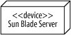 Figure 15-13. An Application Server node marked with the stereotype <<executionEnvironment>>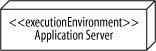 Execution environments do not exist on their ownthey run on hardware. For example, an operating system needs computer hardware to run on. You show that an execution environment resides on a particular device by placing the nodes inside one another, nesting them as shown in Figure 15-14. Figure 15-14. An Application Server node is shown nested in a Sun Server node, meaning that the Application Server runs on Sun Server hardware.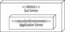 It's not strictly necessary in UML 2.0 to distinguish device nodes from execution environment nodes, but it's a good habit to get into because it can clarify your model.
15.4.1. Showing Node InstancesThere are times when your diagram includes two nodes of the same type, but you want to draw attention to the fact that they are actually different instances. You can show an instance of a node by using the name : type notation as shown in Figure 15-15. Figure 15-15. Showing the name and type of a node; an instance of a Sun Blade Server named svr1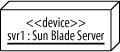 Figure 15-16 shows how two nodes of the same type can be modeled. The nodes in this example, svr1 and svr2, are assigned different types of traffic from a load balancer (a common situation in enterprise systems). Figure 15-16. One node gets read traffic and the other gets write traffic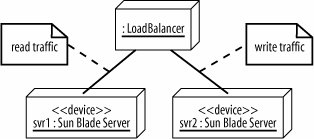 |

EAN: 2147483647
Pages: 175