8.1 Arbitration Protocol
| The structure of a 1394 serial bus is unique in that the transmission media, consisting of many point-to-point connections between pairs of individual ports, are shared through the repetition of packets received on one port to other active ports by each node. The topology of a 1394 serial bus resembles a tree with many intermediate nodes located at branching joints and a single node at the root. All requests for transmission are either filtered out by intermediate nodes or propagated to the root node for an arbitration decision. A permission to transmit is granted by the root node and delivered through intermediate nodes. The configuration of the tree structure and the election of a root node are automatically carried out during the initialization process and after each bus reset whenever a new port joins the 1394 serial bus. An isochronous packet transmission interval is allocated ahead of the asynchronous interval during each cycle, and these transmission cycles are repeated under the guidance of the cycle master who periodically sends cycle start packets. 8.1.1 TopologyThe FireWire transmission system is also called Serial Bus in the IEEE 1394-1995 standards document. A serial bus is different than a serial connection such as RS232, which makes point-to-point connections only. A serial bus is not a conventional bus where multiple devices share a common transmission medium directly. A serial bus connects devices over multiple sections of serial links organized by a communications protocol. The USB (Universal Serial Bus) is another instance of a serial bus. The FireWire serial bus technology addresses both backplane (interior to a computer or communication device) and cable-based transmission physical layers. We only discuss the cable-based physical layer in this chapter. A communication or computing device can have more than one FireWire port. A tree and branch topology is formed when these FireWire ports are interconnected among multiple devices as shown in Figure 8.1. A device can talk to another via these connections. Once permission is granted, a device transmits a packet to its direct neighbors, and they repeat the transmission to their neighbors located further away. Such a device can reach another over multiple devices and links in between. Figure 8.1. Configuration Topology (From IEEE Std. 1394-1995. Copyright © 1995 IEEE. All rights reserved.)
A conventional FireWire cable consists of two shielded twisted pairs, capable of transmitting and receiving in either direction, and one pair of power wires. A conventional FireWire cable is about 4.5 m long. Twisted signal pairs have 28 AWG stranded copper wires inside, and stranded copper power wires are 22 AWG. Each stranded wire consists of seven conductors; 36 AWG for twisted signal pairs and 30 AWG for power wires. There is another shield covering all twisted pairs and power wires as shown in Figure 8.2. Figure 8.2. FireWire Shielded Twisted Pair Cable (From IEEE Std. 1394-1995. Copyright © 1995 IEEE. All rights reserved.)
Because of this unique random tree and branch topology, a connection might need to pass through multiple ports of a device. These power wires are necessary to keep those ports active even when the associated communication or computing device is not powered on. A FireWire cable with power wires is terminated by a unique six-pin plug at each end as shown on the left side of Figure 8.3. Shields of twisted pairs are connected to the power ground while the external shield is linked to metal parts of plugs at both ends. Another type of four-pin plug for terminating FireWire cables without power wires is shown on the right side of Figure 8.3 Figure 8.3. FireWire Cable Plugs
A device with FireWire ports can be considered as a node in the tree branch configuration. A node with only one connection is called a leaf, and a node with more than one connection is called a branch. A node can have a parent port and a number of child ports. A leaf has only one active parent port. A branch has one active parent port and a number of active child ports. The root of the tree has only active child ports. The role of each node, be it a leaf, a branch, or a root, is identified during the serial bus initialization process when multiple devices are interconnected and powered on. After each node is identified, the request for packet transmission over this serial bus is passed up to the root, and the decision for which device to transmit is initiated at the root. 8.1.2 Initialization ProcessThe serial bus initialization process is carried out in three phases: bus initialization, tree identification, and self-identification. The initialization process starts when two nodes are initially connected and repeats whenever a new node joins in. During the bus initialization phase, a bus reset signal forces all nodes into a special state that clears all topology information and thereafter identifies only if each node is a branch, a leaf, or not connected, as indicated by Figure 8.4. In this example, three nodes with only one active port each are identified as leaves, and two nodes with more than one active port are identified as branches. Figure 8.4. A Serial Bus After Bus Initialization (From IEEE Std. 1394-1995. Copyright © 1995 IEEE. All rights reserved.)
A node is elected as the root during the tree identification phase, and all active ports of other nodes are identified as either a parent or a child port depending on whether their connected port is closer to the root as shown in Figure 8.5, where "p" and "ch" stand for parent and child ports, respectively. To elect a root, all leaf nodes send parent notifications to their connected ports first. Branch nodes that received parent notifications from leaf nodes send child notifications as confirmations. Meanwhile, branch nodes send parent notifications through remaining ports. A branch node that received a parent notification before sending out its own parent notification over the same port confirms the child-parent relationship by acknowledging with a child notification. A root contention process starts when two branch nodes exchanged their parent notifications. Each branch node waits a random time before sending out another parent notification during the root contention process. The node that received a parent notification first becomes the parent of the pair in the contention. Figure 8.5. A Serial Bus After Tree Identification (From IEEE Std. 1394-1995. Copyright © 1995 IEEE. All rights reserved.)
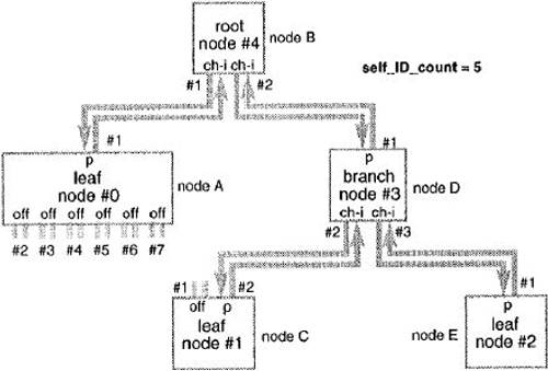
During the self-identification phase, each node selects a unique ID number and sends one to four short self-identification packets over the serial bus to any management entity. These short packets might include timing, power, and transmit throughput information of the sending node. The root starts the self-identification process by asking its first child to do so, and the first child of the root in turn asks its children to do so. The root passes the task of self-identification to its next child after the previous child and all its children have finished and repeats until all its children have finished. The root identifies itself last. The unique ID number of a particular node is the number of times it has noticed that another node has finished its self-identification process. As shown in Figure 8.6, the first child of the root was asked to do self-identification first and has an ID number of 0. Two other leaves obtained ID numbers of 2 and 3 in accordance with the order of doing their self-identification. The root has the highest ID number because it finished the self-identification task last. Figure 8.6. A Serial Bus After Self-identification (From IEEE Std. 1394-1995. Copyright © 1995 IEEE. All rights reserved.)
8.1.3 Media Access via ArbitrationIn the 1394 standards document, the delivery of a packet is called a subaction. 1394 is designed for both asynchronous and isochronous packet delivery. Asynchronous packets carry traditional data information while the delivery of isochronous packets provides channels for digital sound, instrumentation, or other time-sensitive communications. The access to and, thereafter, the delivery of a packet over the transmission media is resolved through an arbitration process among all connected devices. Each FireWire transceiver has two signal pairs, both of which are capable of either transmitting or receiving. During normal signaling, one pair carries a binary data sequence and the other carries a strobe sequence. The clock associated with the data sequence can be recovered by exclusive OR of data and strobe sequences. During arbitration, on the other hand, a node having a pending packet pulls the data pair with its parent to a zero level while examining the signal level on the strobe pair. A parent either grants its children permission to send a packet by pulling its data pair (strobe pair of its child) to a zero level or denies the permission by pulling it to a one level. A parent only relays a request to transmit from its children to its parent and a permission to transmit from its parent to its children. Only one request, the first request in time among all children, is recognized by a parent. The root decides which of its children is granted a permission to transmit. The permission is granted to the child who made the first request in time. Figure 8.7 shows timing relationships of delivering isochronous packets. The transmission of an isochronous packet starts with the arbitration process, which includes the originating node sending a zero level all the way to the root and the root responding with a zero level all the way back. After the permission is granted, the originating node switches to the data prefix signal with a one level on the data pair and a zero level on the strobe pair before signaling of the pending packet. The transmission of an isochronous packet ends by a data end signal with a zero level on the data pair and a one level on the strobe pair. Denied by their parents, all other nodes withdraw their transmission requests and wait for the signal from their parents to disappear. After a silence interval of isochronous gap, those nodes that still have pending packets can send requests to transmit a signal to their parents again. This arbitration process is repeated until all pending isochronous packets are transmitted. Figure 8.7. Delivery of Isochronous Packets (From IEEE Std. 1394-1995. Copyright © 1995 IEEE. All rights reserved.)
Figure 8.8 shows timing relationships of delivering asynchronous packets. A node with a pending asynchronous packet needs to wait for a subaction gap before sending a request to transmit to its parents. Since the subaction gap is bigger, taking a longer time, than the isochronous gap, pending asynchronous packets have to wait until all isochronous packets have been delivered. After they have been delivered, the reception of each asynchronous packet is acknowledged by a short packet within an acknowledge gap. An acknowledge gap is the time required for a receiving transceiver to detect the end of the received packet and to switch to the transmit mode of operation. Isochronous and acknowledge gaps last between 40 to 50 ns while the subaction gap takes about 10 µs. At a velocity of about 5 ns/m, the transmission delay over a 4.5-m FireWire cable is about 22.5 ns. The arbitration time lasts about 2.6 µs because it involves voltage-level relaying over multiple nodes and cables. The data prefix time lasts between 40 and 160 ns and the data end time lasts from 240 to 260 ns. At a transmission throughput of 100 Mbps, a packet of 2000 bytes, or 16,000 bits, lasts about 160 µs. Figure 8.8. Delivery of Asynchronous Packets (From IEEE Std. 1394-1995. Copyright © 1995 IEEE. All rights reserved.)
Because of their time-sensitive nature, isochronous packets are delivered periodically following a special cycle start packet delivered by the cycle master, which maintains a common clock. The nominal cycle period is 125 µs, at an equivalent cycle frequency of 8 kHz, as shown in Figure 8.9. The cycle start packet also contains information on delays, from the scheduled delivery time, caused by extended uses of the media by asynchronous packets. We have isochronous gaps between isochronous packets, acknowledge gaps between asynchronous packets and corresponding acknowledge packets, and subaction gaps between acknowledge packets and next asynchronous packets. Figure 8.9. Cycle Period Structure (From IEEE Std. 1394-1995. Copyright © 1995 IEEE. All rights reserved.)
Let us go through a detailed arbitration examination of two leaves sending to their parents requests to transmit, based on the configuration shown in Figure 8.10. As parents, root and node 3 deny permission of their other children by sending them data_prefix signals while node 3 also relays its children's request to its parent as shown in Figure 8.11. The root then grants the children that sent the first request-to-transmit a permission-to-transmit while node 3 relays the denial from its parent to its child as shown in Figure 8.12. Node 0 starts transmission after the reception of the permission by sending data_prefix as shown in Figure 8.13. The root withdraws the grant signal, and node 0 is ready to send the packet via data and strobe signaling as shown in Figure 8.14. Figure 8.10. Two Leaves Competing for Transmission (From IEEE Std. 1394-1995. Copyright © 1995 IEEE. All rights reserved.)
Figure 8.11. Parents' Responses (From IEEE Std. 1394-1995. Copyright © 1995 IEEE. All rights reserved.)
Figure 8.12. Root Grants a Permission (From IEEE Std. 1394-1995. Copyright © 1995 IEEE. All rights reserved.)
Figure 8.13. Start Transmission (From IEEE Std. 1394-1995. Copyright © 1995 IEEE. All rights reserved.)
Figure 8.14. Root Withdraws the Grant (From IEEE Std. 1394-1995. Copyright © 1995 IEEE. All rights reserved.)
Because there is no collision, for at least one request is granted immediately among multiple devices having pending packets, and no random backoff procedure is involved, the efficiency of the FireWire multiple access process can be calculated based on arbitration duration a, gap time g, and packet length p. We have Equation 8.1
For, a = 2.6, ms, g = 10 ms, and a long packet of p = 160 ms, the efficiency is about Equation 8.2
The efficiency decreases when the packet becomes shorter as a result of fewer bits or higher transmission throughput. For example, for p = 40 ms, representing a transmission throughput of 400 Mbps, we have Equation 8.3
|

EAN: 2147483647
Pages: 97
- Chapter II Information Search on the Internet: A Causal Model
- Chapter VI Web Site Quality and Usability in E-Commerce
- Chapter VII Objective and Perceived Complexity and Their Impacts on Internet Communication
- Chapter VIII Personalization Systems and Their Deployment as Web Site Interface Design Decisions
- Chapter XVIII Web Systems Design, Litigation, and Online Consumer Behavior