4.4 Noise Environment
4.4.1 Noise SourcesWithout electromagnetic shielding, power line cables are sensitive to ingress noises from radio frequency devices and other electromechanical equipment. Partially unbalanced wiring resulting from two-phase appliances and three-way switches makes the noise pickup a little worse. On the other hand, many household appliances, except light bulbs, make severe quasi-stationary or transient noise. Some of them are synchronized to the 60-Hz AC cycle, and others are impulses. Many of them can also come from nearby neighbors sharing the same transformer. From time to time, the noise level from a nearby appliance can exceed the transmit signal level. Information needs to be spread in both time and frequency domains to establish reliable communication links. Information spread in the time domain can be realized using error correction coding techniques while broadband signal should be designed in frequency domain. Some field measurements have shown that a stationary background noise exists at a level of between 150 and 140 dBm/Hz [10] that is 20 to 30 dB above the thermal noise floor of about 170 dBm/Hz. Above the background noise, ingress noise from radio sources can be observed. Some ingress noises are leakages from nearby electrical or industrial equipment and can be characterized by a broad bandwidth and a moderate intensity of about 10 dB above the background noise level. Other ingress noises are from radio stations. Radio station ingresses are characterized by a narrow bandwidth and a high intensity. Clusters of radio stations can be identified within particular bands from ingress noise measurements. Depending on its distance, a radio station ingress noise can be 30 to 40 dB above the background noise. Their intensities also vary depending on the time of the day with the worst ingresses occurring during the late night and early morning when the ionosphere provides the best conditions for radio transmission. Depending upon the proximity, noises from appliances can be very disturbing. A blender with its motor running can raise the noise floor to 80 dBm/Hz, which is 60 to 70 dB above the background noise. Brush motors of appliances such as a blender or a hair dryer generate nonsynchronized noise, while appliances using brushless motors can generate noises synchronized to 60 Hz AC when some TRIACs are in action. Another example of a synchronized noise source is the light dimmer. 4.4.2 Measurement with LISNThe noise level on a power line can be measured using a spectrum analyzer. A special coupling device called LISN (Line Impedance Stabilization Network) is normally used to connect the 50-ohm input of a spectrum analyzer to the power line. A transient limiter might also be required to prevent surge current from entering the spectrum analyzer as shown in the middle of Figure 4.24. A preamplifier might also be necessary between the transient limiter and the spectrum analyzer because many spectrum analyzers have a relatively high noise floor of around 110 dBm/Hz. Depending on the noise floor of the spectrum analyzer, a gain of up to 40 dB might be required for the preamplifier. Figure 4.24. Power Line Noise Measurement
The internal circuit of a part of LISN is shown in Figure 4.25. This circuit shows either the hot or the neutral wire part of an LISN. A switch in the front panel of an LISN can select either the hot or the neutral wire. When selected, either the hot or the neutral wire is connected to the spectrum analyzer via a C-L-C-R network giving a stabilized impedance of 50 ohms at above 100 kHz. Figure 4.25. A Half Internal Circuit of a LISN
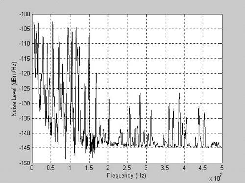
Using an LISN, power line to ground but not differential noise level is measured. A special balanced coupling circuit can be constructed as shown in Figure 4.26 to measure the differential noise level. Figure 4.27 shows a typical power line noise measurement [10]. Figure 4.26. A Balanced Coupling Circuit
Figure 4.27. A Typical Power Line Noise Measurement
4.4.3 Noise ModelsThis measured noise environment on power lines can also be modeled using the controlled random variables method developed in Chapter 3 for the coaxial cable. This noise environment is a combination of the background noise floor at a level of about 145 dBm/Hz, a frequency-dependent radio background noise, strong radio interference carriers within short-wave radio frequency bands, and randomly distributed radio interference carriers. Figure 4.28 shows the ingress noise model. The MATLAB file for generating this noise model appears at the end of this chapter. Figure 4.28. A Power Line Noise Model
|
EAN: 2147483647
Pages: 97