3.7 Noise Environment
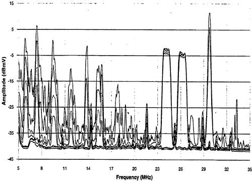
| Transmission characteristics have been extensively field-tested for the purpose of implementing cable modem and other digital services [5]. In the reverse channel frequency band between 5 and 40 MHz, ingress noise level is relatively high. It was found that ingress spectral contents are confined to narrow frequency ranges. Sources of ingress include short-wave broadcasts, HAM band transmission, and CB traffic. In general, the spectral energy density decreases as frequency increases. Figure 3.11 shows one example of many field-collected measurements. There are seven visible plots representing minimum, first decile, first quartile, third quartile, ninth decile, 99th level, and maximum, respectively, in Figure 3.11. In real time, many of these noise peaks show noticeable amplitude vibration. This might be related to the analog modulation nature of these interference signals. Figure 3.11. Ingress Noise Measurements
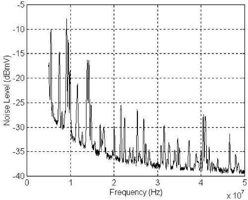
This measured ingress noise environment can be modeled using controlled random variables for transmission performance simulation studies. This noise environment is a combination of a background noise floor at a level of about 40 dBµV, a frequency-dependent radio background noise, strong radio interference carriers within short-wave radio frequency bands, and randomly distributed radio interference carriers. In the implementation of this ingress noise model, a mask for short-wave radio frequency bands is first established according to FCC regulations. In addition, eight groups of random radio inteference frequencies, each of which contains 30 random frequencies, are generated representing eight different interference magnitudes. These additional 240 random radio interference frequencies are incorporated into the short-wave radio mask. Random numbers are then generated representing amplitudes of potential interference carriers at every (discrete) frequency point. These random amplitudes are then applied to interference carriers within short-wave radio bands and those at another 240 random frequencies. The result is further filtered to emulate the bandwidth of interference carriers. Figure 3.12 shows this ingress noise model. Figure 3.12. Noise Environment Model
A digital filter can be constructed according to this noise model. Colored noise can then be generated by passing white noise through this ingress noise filter for simulation studies. For relatively narrow band transmission systems occupying only a part of the frequency spectrum, this ingress noise model can be multiplied with bandpass filters. The combined narrow band ingress noise filter might be easier to implement for simulation studies. In the frequency band between 40 and 52 MHz, the ingress noise level is close to the noise floor of 40 dBµV. Interference carriers in this particular frequency band are also relatively few. |
EAN: 2147483647
Pages: 97