Setting Up and Testing a Two-Tier Cluster Environment
We've assumed that you have installed Microsoft Application Center 2000 (Application Center) on several test computers, and that you are familiar with:
- The Application Center user interface.
- The Registry Editor.
- The Internet Information Services 5.0 (IIS) and COM+ user interfaces.
- The Web Application Stress tool (WAS).
The approach that we're going to take for building our multi-tier environment is to develop the infrastructure in two phases. In phase one we'll build and test the Web tier; in phase two we'll build and test the COM+ application tier.
We'll start by creating a simple Web cluster and running a cross-section of tests to validate the operational consistency of Application Center in this test environment.
NOTE
This section is based on the Pre-Flight Manual, which was developed by the product test team and is included on the Resource Kit companion CD. In addition to the set-up and testing process, they created the sample pages, components, and executables. They've also provided a document named "AC_PreflightCheck.doc" that provides detailed information about the configurations that the team created and tested in the lab.
Build the Web Tier
First we have to create the Web cluster that serves as the front-end tier for a multi-cluster environment. After we've created and tested the Web cluster, we can move on and set up the COM+ applications, or component server cluster. Although you're not restricted to using Microsoft Windows 2000 Network Load Balancing (NLB), we'll use this load-balancing solution on the test cluster.
Create the Load-Balanced Web Cluster
Before starting the cluster creation process, make sure that the following prerequisites have been met.
Prerequisites
In order to create a cluster that uses NLB for load balancing, each server should be running Windows 2000 Server or Windows 2000 Advanced Server; in either case, Service Pack 1 (SP1) and the additional hot fixes need to be installed. These hot fixes are pre-Windows 2000 SP2 and are required for Application Center to run correctly.
Each server must have two network adapters. (See Chapter 5, "Load Balancing.")
The first, or front-end, adapter handles all the public traffic between the cluster members and either Internet or intranet clients. NLB uses the front-end adapter for balancing client requests across the cluster. Since this is the first member we're configuring and it will be the cluster controller, it should have two static IP addresses bound to the adapter. The first IP address is the dedicated, or management, IP address that enables us to communicate directly with each member without using the back-end adapter. The second IP is the cluster IP address—some times referred to as the virtual IP address—which is mapped to the Web site's URL and is common to all the cluster members. All incoming client requests are directed to the cluster IP address.
The second, or back-end, adapter is used for private traffic and outbound traffic to Web clients. Application Center uses this adapter for intra-cluster communications and for supporting its features (such as cluster synchronization) transmitting Application Center heartbeats, and obtaining performance data. This adapter also carries the traffic to back-end databases and/or component servers. In addition to the Application Center cluster services traffic, a typical cluster will access the following network services via the back-end adapter: the domain controller, DHCP server, DNS server, and the Windows Internet Name Service (WINS) server. You can use either static or DHCP-provided IP addresses on the back-end adapter. In this case, we've used an IP address provided by a DHCP server.
The basic cluster configuration looks like the one shown in Figure 8.2, but without the additional member.
NOTE
The configuration in Figure 8.2 does not show additional elements of the network infrastructure, such as switches, routers, hubs, and firewalls. These elements are omitted for the sake of simplicity. All the IP addresses shown are for the purpose of illustration only.
After you've enabled your adapters and bound the IP addresses to them, you can check the adapter configuration by entering the ipconfig command at the Windows 2000 command prompt, and then pressing ENTER. You should get a display that's similar to the one that follows. Notice that we've labeled the two adapters as the "Back-end" and "Front-end"; this isn't required, but it makes it easier to keep track of adapters and their settings in a multi-adapter configuration.
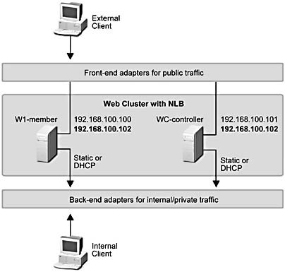
Figure 8.2 Typical network adapter configuration for load-balanced (NLB) cluster members
D:\>ipconfig Windows 2000 IP Configuration Ethernet adapter Back-end: Connection-specific DNS Suffix . : IP Address. . . . . . . . . . . . : 192.168.100.104 Subnet Mask . . . . . . . . . . . : 255.255.255.0 Default Gateway . . . . . . . . . : 192.168.28.1 Ethernet adapter Front-end: Connection-specific DNS Suffix . : IP Address. . . . . . . . . . . . : 192.168.100.100 Subnet Mask . . . . . . . . . . . : 255.255.255.0 IP Address. . . . . . . . . . . . : 192.168.100.102 Subnet Mask . . . . . . . . . . . : 255.255.255.0 Default Gateway . . . . . . . . . : 192.168.28.1
Create a Web Cluster
Now that the server's been configured to function as a cluster controller, we can create the cluster.
- Open the Application Center snap-in: click the Windows 2000 Start button, point to Application Center, point to Programs, and then click Administrative Tools.
- In the Application Center snap-in, in the console tree, right-click Application Center, and then click Connect.
The Connect to Server dialog box appears.
- In the Server name box, enter localhost as the name of the server to connect to and leave the default connection option as Manage cluster for this server, and then click OK.
You can identify the server by providing a valid BIOS name, DNS name, or IP address.
- The New Server dialog box appears, which gives you the option of creating a new cluster or joining an existing cluster.
NOTE
We logged on to the server with an account that has administrative privileges, so it's not necessary to select the Connect as check box and provide administrative credentials. - Create a new cluster, which is what we want to do, is selected by default in the New Server dialog box.
- Click OK to launch the New Cluster Wizard.
- Step through the New Cluster Wizard pages and provide the information requested in each page.
Table 8.2 lists the information we provided when creating and configuring our cluster.
Table 8.2 New Cluster Wizard Configuration Information
| Wizard page | Configuration information, comments |
|---|---|
| Welcome to the New Cluster Wizard | Click Next |
| Cluster Name and Description | Cluster name: RKWebCluster |
| Cluster description: A Web cluster. | |
| Cluster Type | Keep default: General/Web cluster |
| Load Balancing | Keep default: Network Load Balancing (NLB) |
| Monitoring Notifications | E-mail address: someone@microsoft.com E-mail server name: smarthost |
| Completing the New Cluster Wizard | Click Next |
At the end of this process, we have a cluster named RKWebCluster, consisting of the cluster controller, ACDW516AS, which was our localhost system. (Figure 8.3 shows the Application Center snap-in after adding additional members.) The next thing we want to do is increase the size of the cluster by adding two members.
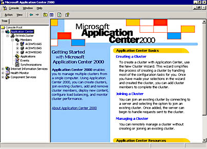
Figure 8.3 The RKWebCluster
Secure your server
A good time to secure the server is after you've created the initial cluster. At this point you can implement some basic security settings for the operating system and the Web server. For information about site hardening and checklists for securing both Windows 2000 and IIS, see Chapter 12, "Security for Administrators and Developers."As a test to show how Application Center replicates IIS settings, try the following. Open the Internet Information Services snap-in on the cluster controller (ACDW516AS in our test cluster), and set the following for all the Web sites:
- Connections limited to 1,000
- Bandwidth throttling enabled
After you add a cluster member, you can check these settings on the member to see if they've been replicated.
The next step in creating our test environment is scaling out the Web tier by adding cluster members.
Add a Member
Adding another server to a cluster only takes a couple of steps. Use Figure 8.3 as a guide for the following steps.
- Right-click Members, on the pop-up menu, point to All Tasks, and then click Add Cluster Member.
The Add Cluster Member Wizard appears.
- On the Welcome to the Add Cluster Member Wizard page, click Next.
- The Name and Credentials page provides a dialog box for identifying the server that you want to add to the cluster.
- You have to provide the name of the computer as well as logon information (User name, Password, and Domain) for an account with administrative privileges on the specified system. (In my test environment, the server I'm adding is ACDW518AS.) When you've finished providing the required information, click Next.
- On the Controller Name page, enter the cluster controller name (or localhost), and then click Next.
After analyzing the configuration of the target system, the Load Balancing Options page appears.
- Accept the page defaults (Set this server to be part of automatic synchronization and Bring the server online after initial synchronization), and then click Next.
- On the last page of the Add Cluster Member Wizard, click Finish.
Application Center replicates all settings to the member, and then the new member adds to the cluster.
At this point we have a two-node Application Center Web server cluster. If you want to add more members, simply repeat the previous procedure.
If you configured the security settings as indicated in the preceding sidebar, you can verify that the controller's settings were replicated to a new member by using the following steps. (Use Figure 8.3 as a guide.)
- Right-click the IIS node, and then on the pop-up menu, click Connect.
- Specify the name of the server to which you want to connect.
This action adds the IIS snap-in for the server that you specify. Through the Application Center user interface, you can use the IIS snap-in for every cluster member.
TIP
You can use this technique to add the Component Services snap-in for each cluster member. On the controller, expand the Component Services node to reveal the Computers folder; right-click, and then when prompted, enter the name of the computer to add. The advantage of adding the snap-ins for cluster members to the controller console tree is that it provides a single interface for managing your cluster. - Open the snap-in for a member, and verify that the settings you established for the cluster controller were replicated when the member was added to the cluster.
Figure 8.4, shows the Default Web Site Properties dialog box (Performance tab) for the default Web site on ACDW802AS. Notice that bandwidth throttling, enabled on the controller, was set on the new member.
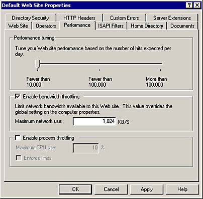
Figure 8.4 IIS settings, which are replicated from the controller to a new member
Validate the Configuration: Visibility
In this validation step, we check to see whether cluster members are visible from within the cluster and from outside the cluster.
Visibility Inside the Cluster
These steps verify server name resolution and connectivity.
From the Controller
- In Windows 2000, open a command prompt, and then use the ping command to verify the presence of the other cluster members.
Each ping should succeed and display results similar to those that follow.
- Ping each of the members by using their machine names:
D:\>ping -a acdw802as Pinging ACDW802AS [192.168.100.104] with 32 bytes of data: Reply from 192.168.100.104: bytes=32 time<10ms TTL=128 Reply from 192.168.100.104: bytes=32 time<10ms TTL=128 Reply from 192.168.100.104: bytes=32 time<10ms TTL=128 Reply from 192.168.100.104: bytes=32 time<10ms TTL=128 Ping statistics for 192.168.100.104: Packets: Sent = 4, Received = 4, Lost = 0 (0% loss), Approximate round trip times in milli-seconds: Minimum = 0ms, Maximum = 0ms, Average = 0ms D:\>
The name should resolve to the back-end adapter's (DHCP or static) IP address (boldface in the preceding display).
- Ping the controller by using its dedicated IP address.
- Ping the virtual IP address.
From All of the Members
- On each member, in Windows 2000, open a command prompt, and then use the ping command to verify the presence of each member on the cluster.
Each ping should succeed with and display results that are similar to the ones shown in the previous example.
- Ping the controller by using its machine name.
The name should resolve to the back-end adapter's IP address.
- Ping each of the other cluster members by using their computer names.
Each name should resolve to the IP address assigned to the corresponding back-end adapter.
- Ping the virtual IP address.
- Optionally, ping the dedicated IP address on each member's front-end adapter.
Visibility Outside the Cluster
From an Internal Client
- On a server outside of the cluster, in Windows 2000, open a command prompt, and then use ping to verify visibility of the cluster members.
- Each ping should succeed with the IP address resolution described next.
- Ping the cluster controller by using its name.
- The name should be resolved to the back-end adapter's IP address.
- Ping each member by using its name.
Each name should be resolved to the corresponding back-end adapter's IP address.
From an External Client
- In Windows 2000, open a command prompt, and then use ping to verify visibility of the cluster members.
- Each ping should succeed with the results described next.
- Ping the controller by using the dedicated IP address on the front-end adapter.
- Ping each member by using the dedicated IP address on the front-end adapter.
- Ping the cluster's virtual IP address.
- Open Microsoft Internet Explorer, and then make an HTTP request to the cluster controller's dedicated IP address (for example, http://192.168.100.102).
- The default Web page for the IIS Default Web Site should be displayed. On a new cluster, such as this one, you should see "This page is under construction".
- Update the page several times by pressing F5 to force the client to retrieve the page from the server rather than from the client's local cache.
- Repeat the preceding test for each of the cluster members, using their dedicated IP addresses.
- As before, the default Web page of the Default Web Site should be displayed with the under construction message.
- Update the page several times.
- Make an HTTP request to the cluster's virtual IP address, and then do the same by using the cluster's virtual IP.
- As before, the default Web page of the Default Web Site should be displayed with the under construction message.
- Update the page several times.
Validate the Configuration: Monitoring
The purpose of this step is to verify that the Application Center monitoring feature works and that the system has access to the logging database via the Microsoft SQL Server Desktop Engine (SQL desktop engine).
NOTE
We've made the assumption that you installed with the monitoring option enabled. If you didn't install this feature, then skip this series of tests and go to "Validate the Configuration: Replication" later in this chapter.
All of the following tests are conducted on the cluster controller by using the Application Center snap-in.
Performance Counters
- Open the Application Center snap-in; in the console tree, expand the cluster node, and then click on the cluster controller name.
- Add three performance counters: Processor Utilization, Web Service GET Requests per second, and ASP Requests per second.
The chart generated by these performance counters should be displayed in the details pane for the cluster controller. (See Figure 8.5.)
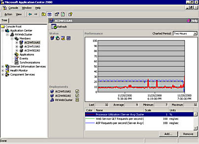
Figure 8.5 The RKWebCluster with performance counters added to the cluster controller
- Repeat the preceding process for each of your cluster members; add the same counters, and then verify that they are installed.
- Finally, click the cluster node (RKWebCluster in our case), and then add the counters.
Application Center will take the data from each member and roll it up to plot an average for processor utilization and totals for GET and ASP Requests per second.
You should get a display similar to the one shown in Figure 8.5 for each of the members.
Events
- Under the cluster controller name, click Events.
- Verify that events from the event log are displayed.
- Enter some filters for Product, Type, and Source, as shown in Figure 8.6.
- Click Filter to apply these filters.
- Verify that the Application Center event system filters the events properly.
- Restore the Events view to its initial state.
- Click Filter.
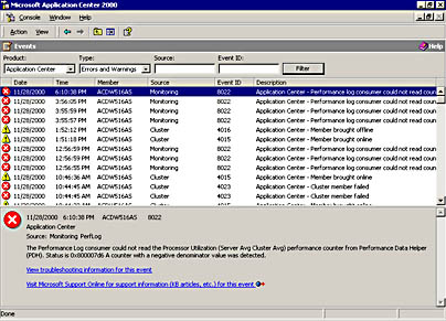
Figure 8.6 Using filters to display Application Center event
- Repeat the event feature testing on each of the cluster members.
Monitors
- Click the cluster controller name, and then click Monitors.
- In the Monitors view, click Check Now.
- Verify that all the icons for the default monitors are green.
NOTE
The default monitors that are installed and enabled by Application Center are:- Cluster Service
- Health Monitor Action Failure
- Memory
- Processor
- Request Forwarding Failure
- Server Offline
- Synchronization Session Failure
- W3SVC
- Repeat this process for each cluster member.
Validate the Configuration: Replication
In this validation step our goal is to verify that the major replication engines are correctly installed and functioning normally. We will use sample Web pages and COM+ components as part of our testing. First, we have to do some preparation by installing sample files that are located on the Resource Kit CD. If you ran the Resource Kit Setup program, these files are installed in the following default directory:
C:\Program Files\Microsoft Application Center 2000 Resource Kit\Pre-Flight Manual
Preparation
This section describes how to install a simple set of Web pages and COM+ components, how to create a simple virtual Web directory, and how to declare them as Application Center resources. They will be used to perform basic replication tests.
On the Cluster Controller
- Locate the file named ACPF.EXE in the Pre-Flight Manual folder. This file is a self-extracting ZIP file that contains all the elements for the Pre-Flight application.
- Execute ACPF.EXE to the partition where Windows and Application Center are installed.
When extracted, ACPF will consist of three folders that contain a collection of Web pages, batch files, configuration files, and executables. You can prepare the cluster controller manually or automate this process by using the batch files that you installed in C:\ACPF directory. (See sidebar.)
Automated setup
You can set up the test Web site, COM+ components, and the Application Center application by running the batch files provided on the CD and extracted to C:\ACPF.
- In Windows 2000, open a command prompt, and then navigate to C:\ACPF.
- Create two COM+ applications, and install six components by running:
C:\ACPF\Files\PFSetupCOM.bat- Create a Web virtual directory under the Default Web Site by running:
C:\ACPF\Files\PFSetupWeb.bat- Create the Application Center application (ACPFApp), and then add the COM+ applications, the Web virtual directory, and the application resources by running:
C:\ACPF\Files\PFSetupAC.bat
NOTE
We recommend the manual approach first to increase your familiarity with the Application Center user interface. Later, you can use the batch files to update configurations on test computers.
Let's step through a manual preparation of the cluster controller. We'll start by creating the two COM+ applications and installing the test components.
In the Application Center snap-in, expand the Component Services node down to, and including, the COM+ Applications folder.
- Right-click the COM+ Applications folder; on the pop-up menu, point to New, and then click Application.
- The COM+ Application Install Wizard appears.
- Click Next.
- On the Install or Create a New Application page, click Create an Empty Application.
- On the Create Empty Application page, for application name, enter AC_PF_VB; for Activation type, use the default setting, Server Application; and then click Next.
- On the Set Application Identity page, use the default setting, Interactive user, and then click Next.
WARNING
In a properly secured production environment, you should not use Interactive user but should specify a specific user. For example, Application Center specifies ACL_servername as the user for its COM+ applications. - On the last wizard page, click Finish to create your new application.
- Expand the newly created AC_PF_VB node; right-click the Components folder; and on the pop-up menu, point to New, click Component to launch the COM Component Install Wizard, and then click Next.
- On the Import or Install a Component page, click Install new component(s).
The wizard opens a file explorer so that you can select the files that you want to install.
- Navigate to the C:\ACPF\Components directory, click PFComponent.dll, and then click Open.
The files that you selected are displayed in the Install new components page.
- Click Next to continue installing the .dll and the PFComp COM+ component.
- On the last page of the wizard, click Finish.
- Repeat the preceding steps to create a second application named AC_PF_VC, and then install TestCOM.dll in this application.
Now we'll build the Web application.
- Expand the IIS node, and then expand the cluster controller node.
- Right-click Default Web Site; on the pop-up menu, point to New, and then click Virtual Directory.
- On the Virtual Directory Creation Wizard Welcome page, click Next.
- On the Virtual Directory Alias page, in the Alias On box, enter ACPFWeb and then click Next.
- On the Web Site Content Directory page, click Browse, locate C:\ACPF, identify it as the content directory, and then click Next.
- On the Access Permissions page, accept the defaults, select the Write check box, and then click Next.
- On the last wizard page, click Finish.
At this point we have a Web site that contains the pages described in Table 8.3.
Table 8.3 Test Files in the ACPFWeb Site
| File name | Description |
|---|---|
| PFWelcome.ASP | Creates a simple COM+ component that calls a method to obtain the server name, and then releases the component. It returns and displays a short message containing the name of the server that returned the page. |
| PFStatic1.HTM through PFStatic5.HTM | This set of static HTML pages is used to display short messages on the screen. |
| PFDynamic1.ASP through PFDynamic5.ASP | This collection of ASP pages displays a short message as well as the name of the server that returned the page. |
| PFDynaCOM1.ASP through PFDynaCOM5.ASP | This collection of Active Server Pages (ASP) randomly creates one of five COM+ components, calls a method on the component, and then releases the component. Each page displays a short message and the name of the server that returned the page, as well as the name of the component that was created. |
The final step in preparing the controller is to create an Application Center application we can use to identify all of the specific resources that are associated with our test application.
NOTE
Application Center applications provide a very useful mechanism for identifying and compartmentalizing application resources for deployment from a stager to multiple cluster tiers.
- In the console tree, under the cluster node, click Applications, and then in the Applications view, click New.
- In the Create a new application dialog box, for the application name, enter ACPFApp, and then click OK.
- In the upper part of the Applications view, click ACPF, click the down arrow to the right of Resource Type, click Web Site and Virtual Directories, and then click Add to activate the Add Resource dialog box.
- Browse down the Web Sites and Virtual Directories tree until ACPFWeb is displayed, click ACPFWeb, and then click OK to add this resource.
- Click the down arrow to the right of Resource Type, click COM+ Applications, and then click Add.
- In the Add Resource dialog box, click AC_PF_VB, and then click OK.
- Repeat the preceding two steps, and add AC_PF_VC as a COM+ Application resource.
- Click the down arrow to the right of Resource Type, click File System Paths, and then click Add.
- Use the Add Resource browser to locate the ACPF folder, and then add the ACPF folder to the application resource list.
NOTE
This resource is not necessary for deploying the Pre-Flight COM+ applications or Web site; however, adding this directory will allow us to test file replication, and there are some scripts in it that will be useful to have on the cluster controller.
When you're finished, your new application and its associated resources will look similar to the one shown in Figure 8.7.
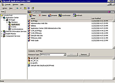
Figure 8.7 The ACPFApp custom application and associated resources
NOTE
You'll notice that the file system path identified as a resource in Figure 8.7 is pointing to the D drive. This isn't an error or mandatory, it's simply the way the test computers are set up for the cluster RKWebCluster. Although we used different partitions, the drive mappings are homogenous on all our test servers and the drives are NTFS formatted.
Although the controller has been prepared by adding our sample files, we should test our installation before proceeding with testing. We'll use the browser to verify that the site we created is functioning correctly.
On an External Client
- Open Internet Explorer.
- Connect to the controller's Web server by specifying the front-end adapter's dedicated IP address in the following URL:
http:// ControllerDedicatedIPAddress/ACPFWeb/PFWelcome.asp
You should see a screen similar to the one shown in Figure 8.8.
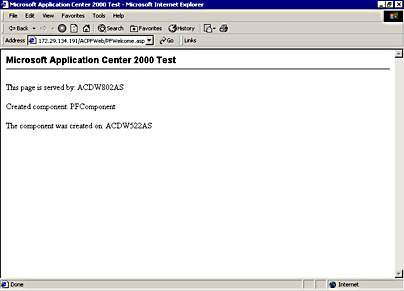
Figure 8.8 Test page served from the cluster controller
Now that we know the site's functioning correctly, let's start replication testing with file replication.
File Replication
Manually Synchronize an Application
- In the console tree, click Applications, and then in the Applications view, click ACPFApp to identify the application.
- Click Synchronize, and then when prompted for confirmation to synchronize the application, click OK.
- In the console tree, click the RKWebCluster node.
- In the details pane, under Synchronization, observe the synchronization icon for ACPFApp.
When the synchronization is finished, the animated icon will change to a check mark.
NOTE
If you open the Synchronizations node in the console tree you can obtain more detailed status information about the synchronization job. For more information about synchronization monitoring and events, see Chapter 6, "Synchronization and Deployment." - Click the cluster controller name to view CPU utilization (it should increase) in the performance chart and the status of the synchronization.
- When the synchronization is finished, verify that the directory and all of its files is replicated on all members.
Trigger an Automatic Synchronization
- Copy some test files to the ACPF directory on the controller.
- Observe to see that the files are automatically replicated.
The Synchronizing icon, under Status for the cluster controller, should change, indicating that an automatic synchronization is taking place.
- Check the ACPF directory on each member to verify that your test files were replicated to each member.
COM+ Replication
Application Center doesn't handle COM+ replication in the same manner as HTML pages or configuration settings. Because the controller doesn't automatically synchronize these components across a cluster, we have to use another approach to getting them on the cluster members.
NOTE
Log on to one of the members, and then open the Application Center snap-in. Expand the Component Services node down to, and including, the COM+ Applications folder. You'll see that the components we registered on the controller are not on the member.
Components can be copied to and registered on cluster members by using the Application Center New Deployment Wizard. The next set of steps is used to deploy the ACPFApp application.
In the Application Center snap-in:
- In the console tree, right-click the Applications node, and then click Deploy Applications.
The New Deployment Wizard appears.
- Click Next to proceed.
The Deployment Target Options page appears.
- By default, the Deployment Target Options page enters the current time and date as the deployment name.
- Enter your own deployment name or keep the default.
The other default on the Deployment Target Options page is to deploy content inside the current cluster, which is what we're going to do.
- Click Next.
- On the Deployment Targets Within the Cluster page, which enables us to specify where we want to deploy the application, click to highlight the member names that are listed, and then click Next.
NOTE
In RKWebCluster, the member names are ACDW518AS and ACDW802AS, so these were selected.The Deployment Content page, which allows you to deploy the entire server image or a specific application(s), appears.
- Because we want to deploy a specific application, leave the default option button selected; in the list of available applications, click ACPFApp; and then click Next.
- Because we don't want to use the default selection on the Deployment Options page (folder and file permissions) but we do want to deploy COM+ applications instead, change the selection, and then click Next.
- Click Finish to start the deployment.
You can monitor the deployment process by selecting the cluster controller node in the console tree and watching the counters and status messages that appear in the details pane for the controller. The Synchronizations view provides extensive information about deployments. After the deployment is finished, check the Component Services COM+ Applications folder for each member and verify that the sample components were copied to the members and registered.
Optional Replication Test
- Remove one or more COM+ components from the AC_PF_VC application or change a component's properties (for example, transaction affinity, synchronization, or object pooling).
- Deploy the ACPFApp application again.
- After the cluster is synchronized, check the members to see if the changes are implemented on the local copy of the components.
- When you're finished testing, restore the original configuration because we need these settings for additional tests.
Registry Replication
- On the controller, start the Registry Editor, and then create a new key (for example, HKEY_LOCAL_MACHINE\Software\TestKey).
- Add a value (for example, TestValue) of the data type REG_SZ, string.
- For the key's value, enter a test string, such as A test key.
- In the console tree, click the Applications node, and then in the Applications view, click ACPFApp.
- Next, add the test registry key to this application as a resource. In the Resource Type box, click Registry Keys, and then click Add.
- Navigate the registry by using the Add Resource dialog box to locate TestKey, and then click OK to add the key to the ACPFApp resource list.
- In the upper part of the Applications view, click ACPFApp, and then click Synchronize.
- After the application is replicated to the members, check the settings on each member to verify that this synchronization worked.
- You can check the individual registry settings on each member as well as the resource list for ACPFApp on each member.
- You should repeat this test a couple of times; try adding another test key, deleting a test key, or changing the values of a test key.
Metabase Replication
We'll test the replication of metabase settings by altering some of the values stored by IIS.
- Click on the Internet Information Services node in the Application Center UI, and expand it down to and including Default Web Site for the cluster controller (ACDW516AS in RKWebCluster).
- Right-click on ACPFWeb to open the ACPFWeb Properties page.
- Change a property, such as Execute permissions, and click OK to save the changes.
- Synchronize the cluster.
- Check the metabase settings for the ACPFWeb directory on each of the members.
- Restore the original settings on the cluster controller, and synchronize the cluster again. Verify that the original settings were restored on each member by this synchronization.
Validate the Configuration: Request Forwarding
This series of tests will verify that request forwarding works, as well as demonstrate this feature.
Preparation
We'll start by verifying that the cluster is accessible via the cluster or virtual IP address that's shared by all the members. Open Internet Explorer on a system outside the cluster, and provide the following URL, using the cluster IP address in the root:
http://<cluster_ IP_address>/ACPFWeb/PFWelcome.asp
After the screen is displayed, refresh it several times to confirm that the cluster is serving this page correctly.
NOTE
Use Ctrl-F5 to refresh pages in the browser. This forces the browser to retrieve the requested page from the server rather than pulling it out of a cache.
We created this cluster using NLB with a client affinity set at Single. For the next set of tests, we need to change this affinity to Custom (None). The reason for doing this is that we need to ensure that no session stickiness, which can trigger the request forwarder, is maintained.
TIP
In general you should use an affinity setting of Custom (None) when conducting localized testing of clustered Web servers. This is due to the nature of the algorithms that NLB uses to distribute load using IP address ranges. Typically, clients on the same internal subnet—provided that you're using Class C affinity—will end up getting balanced to the same server in a cluster. And, if you're using Single affinity, internal clients will always have their requests sent to the same Web server and you won't be able to observe request forwarding. Chapter 10, "Working with Performance Counters," covers this subject in more detail.
- Right-click on the cluster name in the Console tree, and select Properties.
- Change the cluster client affinity by selecting Custom (none) in the Network Loading Balancing options drop-down, and click OK. This change in client affinity, and the load-balancing algorithm, will be replicated to the cluster members.
Static Content – Not Forwarded
Now we'll test static content that isn't forwarded. Open the Web browser on an external system, and connect to the cluster, using the cluster IP address in the following URL to retrieve "PFStatic1.htm":
http://<cluster_IP_address>/ACPFWeb/PFStatic1.htm
After the screen displays, refresh the screen 10 - 20 times. Open the Web server log file on the controller and the members to verify that this page was opened on different servers. The log files are in the following path: C:\WINNT\system32\LogFiles\W3SVC1.
Dynamic Content – Forwarded by Default
Use the Web browser on the external client to connect to the cluster using the cluster IP address in the following URL to retrieve "PFDynamic1.asp":
http://<cluster_ IP_address>/ACPFWeb/PFDynamic1.asp
Verify that the page is properly displayed. The page returns short text with the server name. Refresh the screen 5 _ 10 times. In every instance you should see the same server name displayed. Remember, with request forwarding enabled, subsequent requests from the same client are always returned from the server that initially handled the request.
Dynamic Content – Not Forwarded When Request Forwarding Is Turned Off
Now we'll disable request forwarding. Once again, we're working in the controller user interface. Right-click on the cluster name, and select Properties. When the cluster properties page appears with the General tab displayed, click the Advanced button that's located in the Load balancing options section. This will bring up the Advanced Load Balancing options screen, and you can deselect the Enable request forwarding check box. Click OK to apply the change.
Use the browser on your external client to connect to the cluster, using the cluster IP address in the following URL to retrieve "PFDynamic1.asp":
http://<cluster_ IP_address>/ACPFWeb/PFDynamic1.asp
Verify that the page is properly displayed. The page returns short text with the server name. Refresh the screen 5 – 10 times. Because request forwarding is turned off, you should see different server names displayed.
NOTE
Remember to restore the Single affinity setting and to turn request forwarding back on at the end of your testing.
Validate the Configuration: Put Load on the Cluster
Now that we've verified that all of Application Center's major features are functioning correctly, we'll apply some load to the cluster as a final step in validating the configuration.
Preparation
Before running any tests, we have to do some preparation, starting with an external client.
On an External Client
Since we use the Web Application Stress tool (WAS), you'll have to obtain a copy and install it on the client system that you're going to use for testing. If you don't already have a copy, you can download the latest version from http://webtool.rte.microsoft.com.
NOTE
The WAS tool is used extensively in Chapter 10, "Resolving Performance and Capacity Issues." Refer to this chapter for more detailed information about configuring and using this tool.
Locate the file named ACPreflight.mdb in the ACPF directory. This file is a Web Application Stress database that contains a script that the test team designed to test the configuration we've created. It loops through calls to the pages described earlier, randomly specifying COM+ components to create.
Start WAS, and open ACPreflight.mdb to load the test script. You'll have to edit this script for your test environment as follows:
- Specify the cluster IP address for the cluster you created.
- Change the duration of the test from one minute to 15 minutes, the minimum time for counter performance graphs.
- Since this particular application doesn't use sessions, you can disable the "Use users, passwords, and save cookies" option. This prevents skewing of the results.
NOTE
Turning off the "users, passwords, and save cookies" feature in WAS is fine for quick and dirty tests; as long as the application does not use cookies (not session cookies), no authentication is required, and the %USERNAME% and %PASSWORD% string replacements are not used in the query string. Additionally, static headers are fine as long as the application does not use dynamic cookies. However, a better approach is to leave these WAS settings enabled, and use the cluster configuration settings contained in the next section, "On the Cluster Controller."
Each of the tests in the script is executed on the cluster using a simulated load, and the results are stored in a report that WAS generates after a test run.
On the Cluster Controller
If you're using internal WAS clients, you should set the client affinity to Custom (None) in order to get better load distribution on the cluster. To do this, right-click on the cluster node, select Properties, and on the General tab, use the drop-down list for the NLB client affinity option to choose Custom (None).
Disable Request Forwarding by right clicking on the cluster node, select Properties, choose the Request Forwarding tab, and uncheck "Enable Web request forwarding". There are two reasons for doing this.
First, unless you're running WAS clients through a proxy server and the application that you're testing requires request forwarding, leaving Request Forwarding enabled serves no purpose.
Second, disabling Request Forwarding is, in most test scenarios, the preferred alternative to turning off the "Use users, passwords, and save cookies" feature in WAS is to disable Request Forwarding. This is preferable since many Web applications do require string replacements in the querystring, do require authentication, and do use cookies. Also, the request header size is a more accurate when monitoring bandwidth (303 bytes instead of 202 or 185).
Basic Tests with Load on Cluster
Before conducting any testing, follow the next set of steps to verify that the ACPreflight script is functioning correctly:
- Start the script.
- Use the Application Center user interface to observe the performance counters that you set for Processor utilization and GET requests for on each cluster server. The performance graphs for each server should all be within the same range, indicating the requests are being load-balanced across the cluster.
NOTE
Processor utilization for the controller will be slightly higher, which is to be expected. - Check the cluster performance monitor—notice how the counters for the individual servers are rolled up and averaged, providing a cluster-wide view of performance.
After the script is finished running, check the WAS report file that was generated. It contains information such as the number of requests, requests per second, socket errors, and error codes.
Some Tests to Try
Run the test script against your cluster, and carry out the following activities. In each case, observe the effect that each activity has on controller, member, and cluster-wide performance.
- Set a member offline from load balancing. Right-click on the member name, and select Set Offline. Since we're running in a test environment, there's no need to drain connections—choose the Take offline now option on the Set Offline screen, and click OK. Processor utilization should increase on the remaining servers.
- Reverse the preceding process, and bring a server online. Processor utilization should come down for the original two servers.
- Remove one of the members from the cluster. Right-click on the member name, and click on Remove Cluster Member under All Tasks. Click OK to confirm the removal, and provide the required credentials when prompted. Click OK. After the member is removed, processor utilization should be higher on the remaining servers.
- Nominate one of the members to be the cluster controller. Right-click on the member name, and select All Tasks, Designate as Controller. Observe the impact that this action has on processor utilization as the Application Center reconfigures the cluster.
- Repeat the replication and deployment steps that you conducted earlier.
- Change the cluster's bandwidth, and process throttling settings.
- Turn request forwarding on and off.
Scale Out the Web Tier
For a final test of the product's features, try scaling out the Web tier by adding a new system that has Application Center installed but hasn't been used on a cluster. For our test environment, we added one more server (ACDW802AS), so the final Web cluster consists of the following servers in the Figure 8.1 architecture:
- ACDW516AS, cluster controller (WC)
- ACDW518AS, a cluster member (W1)
- ACDW802AS, a cluster member (W2)
Add the new member's snap-ins—that is to say, IIS and Component Services—to the cluster controller's console, and verify that the configuration settings and application installs that you did in the preceding sections were replicated to the new member. Figure 8.9 shows the controller console in the RKWebCluster after all the snap-ins were added.
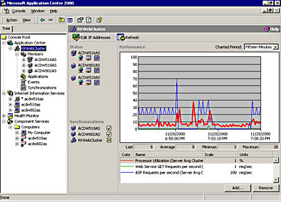
Figure 8.9 The RKWebCluster controller console tree with member snap-ins added
The few tests that we've described provide the foundation for verifying that your cluster is functioning correctly, as well as give you a preliminary understanding of cluster performance. Your own situation may require custom testing that reflects the needs of your platform and applications.
Let's move on and build the back-end tier of our environment—the COM+ application cluster for serving out-of-process components to the front-end Web tier.
Build the COM+ Tier
In this step, we'll create a two-member cluster that will be used to serve COM+ components to Web servers on the front tier. After creating the COM+ cluster, we have to configure the Web cluster members so that they will route requests to the component cluster. CLB in fact, is implemented on the Web tier rather than the COM+ tier.
Create the COM+ Cluster
Before starting the cluster creation process, make sure that the following prerequisites have been met.
Prerequisites
The configuration, shown in Figure 8.10 requires the same software as the Web cluster. The notable difference is that because this cluster doesn't use NLB, only one static IP address is required on the front-end adapters. Unlike members in the Web cluster, component servers don't share a cluster/virtual IP and media access control (MAC) address. When a Web server needs to route a request to a component server, it uses the component server's machine name. Once again, the back-end adapters, which are not a requirement, could be used for carry Application Center-specific traffic.
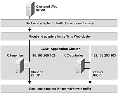
Figure 8.10 Typical network adapter configuration for a COM+ application cluster
Before opening the Application Center snap-in and creating the cluster, you should use ping to verify the visibility of the computers on the network.
Create a COM+ Application Cluster
Now that the server's been configured to function as a cluster controller, we can create the cluster. Because the steps that you're going to take to create this cluster are identical to those used for creating the Web cluster, we've provided the following summary.
- On the computer that you want to use as the cluster controller, open the Application Center snap-in.
- Connect to the computer as localhost, and then in the New Server dialog box, click New Cluster to launch the New Cluster Wizard.
- Step through the screens in the New Cluster Wizard.
Because we're not implementing NLB on this cluster, refer to Table 8.4 and take note of the slightly different configuration information that we used to build RKCOMCluster, our test component server cluster.
Table 8.4 New Cluster Wizard Configuration Information for the COM+ Application Cluster
| Wizard page | Configuration information, comments |
|---|---|
| Welcome to the New Cluster Wizard | Click Next |
| Cluster Name and Description | Cluster name: RKCOMCluster |
| Cluster description: A COM+ application cluster. | |
| Cluster Type | Click COM+ application cluster |
| COM+ Application Clients | Kept default: Server applications |
| Monitoring Notifications | E-mail address: someone@microsoft.com E-mail server name: yourmailserver |
| Completing the New Cluster Wizard | Click Next |
At the end of this process we have a cluster named RKCOMCluster, consisting of the cluster controller, ACDW522AS. The next thing we want to do is increase the size of the cluster by adding one member.
Add a Member
Adding another cluster member only takes a couple of steps. Repeat the steps you used to add a member to the Web cluster. (The assumption is that you are doing this while logged on to the cluster controller.) In brief:
- Right-click the cluster controller node; on the pop-up menu, point to All Tasks, and then click Add Cluster Member to launch the Add Cluster Member Wizard.
- Identify the server to add, and provide valid credentials.
- Enter the cluster controller name.
- Complete the wizard steps.
At this point we have a two-node Application Center COM+ application cluster. If you want to add more members, simply repeat the previous procedure.
For our test environment, the final cluster consists of the following servers in the Figure 8.1 architecture:
- ACDW522AS, cluster controller (CC)
- ACDW811AS, a cluster member (C1)
As a final set up step, we added the IIS and Component Services snap-ins for ACDW811AS to the controller console tree so that we could have a single management console for the cluster, in the same fashion as the Web cluster controller.
Validate the Configuration
You should take the time to test the cluster configuration before installing any applications. You can do this by repeating most of the tests described for testing the Web cluster. The key difference is that HTTP- and NLB-related tests aren't relevant for the COM+ cluster. You don't have to worry about request forwarding, which is an advanced load balancing option, because load balancing isn't enabled for this cluster.
However, you can install performance counters—processor utilization as a minimum—as well as verify that monitoring is working.
Install the Components
Now we have to install the same COM+ applications that went on the Web tier to the component servers. (If you haven't already done so, execute the Pre-Flight Manual's ACPF.EXE to the partition where Application Center is installed.)
- Navigate to the ACPF\Files directory.
- In Windows 2000, open a command prompt, and then type:
C:\ACPF\Files\PFSetupCOM.bat
Create an application named ACPFApp and add the test COM+ applications as resources for this application. Once again, we'll use a batch file to do this.
- In Windows 2000, from the command line, type:
C:\ACPF\Files\PFSetupACCom.bat
- At this point we have two COM+ applications, and one Application Center application that has both the COM+ applications registered as resources. Now we have to deploy ACPFApp to the cluster member in order to replicate the COM+ applications and install them correctly. In the Application Center snap-in, right-click the cluster name, and then on the pop-up menu, click Deploy Applications to deploy ACPFApp to the member by using the New Deployment Wizard.
NOTE
Make sure you specify Deploy COM+ applications on the Deployment Options page. - When the deployment is finished, do a visual check on the member and verify that the COM+ application is installed correctly.
The final step involves configuring the Web cluster controller so that the test components will be load balanced and their activations will occur on the COM+ servers.
Enable CLB on the Web Cluster
- Log on to the Web cluster controller, and then open the Application Center snap-in.
- Expand the Component Services snap-in for the controller and verify that both the AC_PF_VB and AC_PF_VC applications have their components installed.
After we enable the components in both applications for load balancing, we'll create the routing list needed to forward component requests to the COM+ cluster members.
Enable CLB
In the console tree, expand the Component Services node down to the component level, and in the AC_PF_VB application, reveal PFComponentPFComp. Figure 8.11 illustrates the fully expanded component snap-in on the RKWebCluster controller.
To enable load balancing:
- Right-click PFComponentPFComp, and then on the pop-up menu, click Properties to open the object Properties dialog box.
- Click the Activation tab.
- Select the Component supports dynamic load balancing check box, as illustrated in Figure 8.11, and then click OK to save your changes.
Next we have to enable load balancing for the components in the other test application.
- Under the AC_PF_VC node, expose the components, and then repeat the preceding steps to enable load balancing for each of the components (TestCOM.TestCOM1 through TestCOM.TestCOM5) in this application.
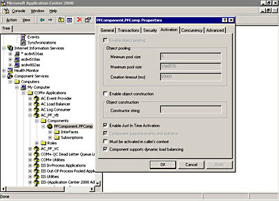
Figure 8.11 The dialog box for enabling dynamic load balancing on a COM+ component
Automated CLB configuration
You can also mark all the test components for dynamic load balancing by using a batch file provided with the Pre-Flight Check Application. In Windows 2000, open a command prompt, type the following batch file name, C:\ACPF\Files\PFSetupCOMDLB.bat, and then press Enter.
The next step in enabling CLB on our Web cluster is creating a routing list that references the COM+ cluster members.
Create the Routing List
- Right-click the cluster node (RKWebCluster in our cluster), and then on the pop-up menu, click Properties.
The RKWebCluster Properties dialog box appears (Figure 8.12).
- Click the Component Services tab.
- Add the name of each member in the COM+ cluster, and then click OK to save this configuration.
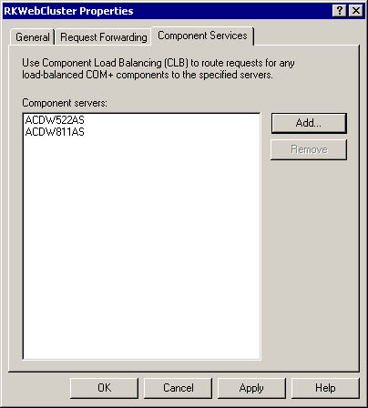
Figure 8.12 A routing list identifies component servers that handle component requests
As you can see in Figure 8.12, we identified both of the RKCOMCluster members as targets for object instantiation requests.
Finally, we have to copy all the configuration information that we just did on the controller to the other Web cluster members. Once again, we use the deployment wizard and cluster synchronization to do this. The wizard copies the components and their new settings to each member, and synchronization copies the cluster routing list information to the members.
Use the following steps:
- Deploy the ACPFApp application from the controller to the members; remember to specify Deploy COM+ applications on the Deployment Options page.
- Perform a visual check, and verify that the newly installed components have dynamic load balancing enabled.
- Synchronize the cluster (right-click the controllername, and then on the pop-up menu, click Synchronize) to make sure that each member has the updated routing list.
At this point CLB is enabled on our two-tier cluster environment and we can proceed with some basic testing.
Validate the Configuration: Load-Balanced Components
You should perform the following tests to verify that component creation is taking place on the COM+ tier, and that these instantiations are being load balanced between the two component servers.
On the External Client
Use the following steps to verify how the configuration works.
- Open the Web browser, and then use the cluster IP address to connect to the Web cluster.
- Use the following URL to open the PFWelcome.asp page:
http://WebclusterClusterIPAddress/ACPFWeb/PFWelcome.asp
- Verify that your test environment correctly serves the Web page, which shows:
- The name of the Web server that returned the page.
- The name of the COM+ component that was instantiated.
- The name of the COM+ application cluster member that created the component.
- Update the screen several times by pressing CTRL+F5.
You should see different Web and COM+ server names as you generate requests.
NOTE
Your Web cluster should have request-forwarding disabled, and as mentioned earlier, should use an affinity setting of Custom (None).
Validate the Configuration: Put Load on the Clusters
We also want to apply some load to our multi-tier configuration so that we can observe how the servers on both tiers respond. Start WAS, and run the test script that we used earlier. While the stress test is running, you should:
- Observe processor utilization and ASP Requests per second on the Web servers.
- Check the processor utilization on the members in the component cluster.
- Open the Component Services snap-in on one of the component members, and verify that both applications are running and all of the COM+ components are created at least once.
When the script finishes running, examine the report that's generated for the run:
- Check for errors.
- Check for failed connections.
NOTE
It may be necessary to apply more load to the clusters. You can install WAS on other clients and add their names to the client list on the system that ran the ACPreflight stress test script. This allows you to manage stress tests from a single console.
Once again, you can conduct more extensive testing by running the WAS script against the clusters and trying different tasks, such as setting members online and offline in the Web tier, or removing members.
The RKWebCluster under load
In our test environment, the load results (running two WAS clients against the cluster) clearly showed that one of our members, ACDW802AS, could not handle the same load as the other two members. Even the controller, which also had to handle the various Application Center services, showed processor utilization that was at least 10 percent lower than ACDW802AS. In Chapter 10, "Working with Performance Counters," you'll see how these members can be tuned for better performance, as well as how you can re-distribute cluster traffic to compensate for lower capacity members.
Summary
Up to this point we've been working with test clusters that weren't actively serving content to clients. In this situation it didn't really matter if services such as COM+ or IIS got reset because it didn't affect live users. In a production situation, however, you can't do this—a staging and deployment process and platform is essential for installing or refreshing applications on a production cluster. In the following section we'll set up an Application Center stager that we'll use for deploying applications.
EAN: N/A
Pages: 183