Application Center and Load Balancers--Concepts
Application Center uses a slightly different representation and terminology for clusters than that used by the different load-balancing device manufacturers. The principle difference between the way that Application Center views a cluster and the way a load-balancing device views a cluster is the absence of a server-grouping concept.
NOTE
The Application Center view of a cluster is due to the fact that Windows Network Load Balancing does support load balancing of multiple virtual IP addresses. However, it does not implement port differentiation, which is to say, having one virtual IP address with two different ports, each one representing a different cluster.
The other notable conceptual difference relates to services and members. Table 13.2 provides a mapping between the Application Center concept of a cluster, service (for example, HTTP and FTP), and member and the supported devices.
Table 13.2 Application Center and Device Conceptual Mapping
| Application Center | Alteon WebSystems 180E | Cisco Systems LocalDirector | F5 Networks BIG-IP | Intel NetStructure 7175 and 7185 |
|---|---|---|---|---|
| Cluster | Virtual Server | Virtual Server | Virtual Server | Policy Group |
| Service1 | Real Server Group | Pool | Service | |
| Member | Real Server | Real Server | Member | Server |
1 This release of Application Center does not support the concept of a service.
The following sections provide an overview of each device and show how each maps to the Application Center concept of a cluster and its members.
Alteon WebSystems 180E
Figure 13.2 shows how Alteon WebSystems 180E device settings map to the main elements of an Application Center cluster: the cluster, the virtual or cluster IP address, and cluster members.
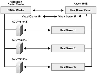
Figure 13.2 Architectural mapping between Application Center and the Alteon WebSystems 180E load balancer
Table 13.3 summarizes the Alteon WebSystems 180E server management entities and their available configuration options.
Table 13.3 Server Management Entities for the Alteon WebSystems 180E Device
| Entity | Configuration options |
|---|---|
| Virtual Server | Server name IP address Port number Pool(s) |
| Real Server Group | Name Load-balancing mode Members |
| Real Server | IP address Port number Load-balancing weight |
Cisco Systems LocalDirector
Figure 13.3 shows how Cisco Systems LocalDirector device settings map to the main elements of an Application Center cluster: the cluster, the virtual or cluster IP address, and cluster members.
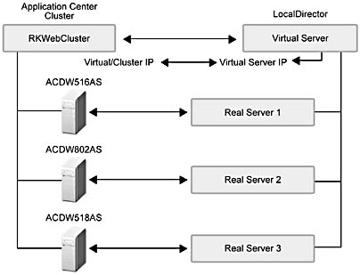
Figure 13.3 Architectural mapping between Application Center and the Cisco Systems LocalDirector load balancer
Table 13.4 summarizes the Cisco Systems LocalDirector server management entities and their available configuration options.
Table 13.4 Server Management Entities for the Cisco Systems LocalDirector Device
| Entity | Configuration options |
|---|---|
| Virtual Server | Name IP address Port number Pool(s) |
| Real Server | IP address Port number |
F5 Networks BIG-IP
Figure 13.4 shows how F5 Networks BIG-IP device settings map to the main elements of an Application Center cluster: the cluster, the virtual or cluster IP address, and cluster members.
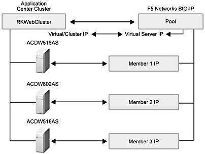
Figure 13.4 Architectural mapping between Application Center and the F5 Networks BIG-IP load balancer
Table 13.5 summarizes the F5 Networks BIG-IP server management entities and their available configuration options.
Table 13.5 Server Management Entities for the F5 Networks BIG-IP Device
| Entity | Configuration options |
|---|---|
| Virtual Server | Name IP address Port number Pool(s) |
| Pool | Name Load-balancing mode Members |
| Member | IP address Port number Load-balancing weight Priority |
Intel NetStructure 7175 and 7185
Figure 13.5 shows how Intel NetStructure 7175 and 7185 device settings map to the main elements of an Application Center cluster: the cluster, the virtual or cluster IP address, and cluster members.
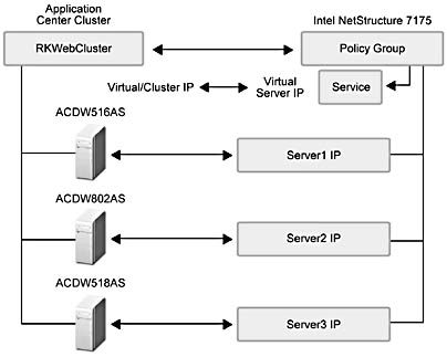
Figure 13.5 Architectural mapping between Application Center and the Intel NetStructure 7175 and 7185 load balancer
Table 13.6 summarizes the Intel NetStructure 7175 and 7185 server management entities and their available configuration options.
Table 13.6 Server Management Entities for the Intel NetStructure 7175 and 7185 Device
| Entity | Configuration options |
|---|---|
| PolicyGroup | Name Service(s) |
| Service | Virtual IP address Port number Balancing mode Server(s) |
| Server | IP address Port number |
EAN: N/A
Pages: 183