Lesson 3: ROM BIOS
In addition to the chip set, you will find other chips called ROM BIOS. A ROM BIOS chip contains data that specifies the characteristics of hardware devices, such as memory and hard disk and floppy disk drives, so the system can properly access them. This lesson explores ROM BIOS and what it does.
After this lesson, you will be able to:
- Identify the different types of ROM.
- Modify the CMOS settings in a computer.
- Identify POST codes and take appropriate corrective action when a problem is identified.
Estimated lesson time: 30 minutes
ROM BIOS
ROM (read-only memory) is a type of memory that stores data even when the main computer power is off. This is necessary so that the system can access the data it needs to start up. When stored in ROM, information that is required to start and run the computer cannot be lost or changed. The BIOS, software in the form of programs stored on ROM chips, is used during the startup routine to check out the system and prepare to run the hardware. The system BIOS is a ROM chip on the motherboard used by the computer during the startup routine (boot process) to check out the system and prepare to run the hardware. The BIOS is stored on a ROM chip because ROM retains information even when no power is being supplied to the computer. The downside of storing data in an older computer's ROM is that we have to change a chip to update information.
More recent systems use a technology called flash ROM or flash BIOS that allows code in the core chips to be updated by software available through the BIOS or motherboard supplier. Check the Internet site for the supplier if you suspect your ROM chip has flash ROM technology; the software and instructions are generally downloadable.
CAUTION
Upgrade a BIOS only when necessary! Be sure to follow all precautions included with the motherboard manual and instructions for the upgrade. Improper installation can render the motherboard useless.
BIOS (also referred to as firmware) can be subdivided into three classes, depending upon the type of hardware it controls.
- The first class, called core chips, includes support for hardware that is common to all computers, is necessary, and never changes.
- The second class, called updatable chips, encompasses hardware that is also common and necessary, but that might change from time to time.
- The third class of chips includes anything that is not included in one of the first two classes.
Core Chips
Look on any motherboard: ROM chips for the core chips are found everywhere. They are distinctive because they are in DIP (dual inline package) form and are almost always labeled. These chips are commonly used for the keyboard, parallel ports, serial ports, speaker, and other support devices. Each ROM chip contains between 16 and 64 KB of programming.
Updatable Chips
Several devices on a computer often contain their own flash BIOS or updatable ROMS. These include SCSI controllers and video cards. Because this information is subject to change (for instance, you can upgrade a hard disk drive or change a video card), it is stored on a special chip called the CMOS (complementary metal-oxide semiconductor). This chip gets its name from the way it is manufactured, not from the information it holds.
Unlike other ROM chips, CMOS chips do not store programs; they store data that is used by the BIOS for the programs needed to talk to changeable hardware. The CMOS chip also maintains date and time information when power to the computer is off.
The CMOS chips can store about 64 KB of data. However, to store the data needed to boot a computer requires only a very small amount of memory: about 128 bytes. If the data stored on the CMOS is different from the hardware it keeps track of, the computer, or part of it, will probably not work. For example, if the hard disk drive information is incorrect, the computer can be booted from a floppy disk, but the hard disk drive might not be accessible. The technician or owner will have to reset the CMOS values before the computer can use the device if it is not properly defined in the CMOS registry.
The information contained in a CMOS chip will depend on the manufacturer. Typically, CMOS contains at least the following information:
- Floppy disk and hard disk drive types
- CPU
- RAM size
- Date and time
- Serial and parallel port information
- Plug and Play information
- Power Saving settings
IMPORTANT
It is critical that the core information on a CMOS chip be correct. If you change any of the related hardware, the CMOS must be updated to reflect those changes.
Updating CMOS
To make changes to a CMOS chip, you need to run a CMOS setup program. This application is independent of the operating system, because it must work even if an operating system is not loaded, or even if there is no form of disk drive. The way to start this program depends on the manufacturer of the BIOS, not the manufacturer of the computer. Manufacturers of motherboards purchase the BIOS from other companies, most of which specialize in making these chips. Many different computer suppliers use the same BIOS. The BIOS manufacturer and version number is the first thing you see displayed when you boot up your computer. Figure 6.3 shows examples of startup information for three different types of BIOS chips.
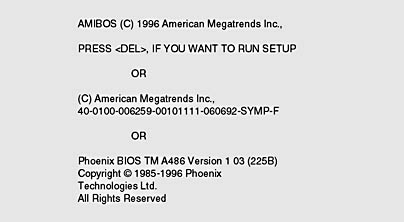
Figure 6.3 BIOS information
Although several companies write BIOS code and sell it to computer makers, three companies—American Megatrends (AMI), Phoenix, and Award—dominate the BIOS market. Motherboard vendors might use one supplier for a series of products; however, it is not uncommon for a manufacturer to change sources within a series due to design or cost considerations. A good technician should be familiar with the basic CMOS setup procedures for BIOSs manufactured by all three.
Because of its flexibility, the Hi-Flex BIOS, manufactured by AMI, has taken a large share of the computer market. Motherboard manufacturers can purchase a basic BIOS from AMI and then add setup parameters to meet the needs of their products. For this reason, the number of setup parameters available on one computer can differ from those on another computer that is based on the same motherboard. Award competes directly with AMI, providing very flexible BIOS chips. Award was the first BIOS to heavily support PCI (Peripheral Component Interconnect) motherboards.
Phoenix is considered a manufacturer of high-end BIOS. Phoenix creates individual BIOS chips for specific machines. As a result, Phoenix BIOS chips have fewer setup parameters available. These chips are commonly used in machines with proprietary motherboards, such as laptops. Vendors can tune the BIOS for performance, basing new code on the Phoenix core.
There are several ways to determine who the BIOS manufacturer is:
- Watch the monitor when the computer boots. A BIOS screen will usually be displayed, indicating the manufacture and version number. (This screen might not be visible if the computer is warm-booted. In that case, power off the unit and restart.)
- Check the computer or motherboard manual. Most include a section on entering the setup program and setting options.
- Remove the cover of the computer and look at the chip. Most BIOS chips have a manufacturer's label.
- Try a good third-party utility program. These products are available at almost any software store. A Web search for a key phrase such as "BIOS diagnostic" will yield the names of a number of them.
- Reboot the computer and hold down several keys at once or unplug a drive. This will often cause an error and prompt you to get into the setup program. Unplugging the keyboard will accomplish the same goal with less work; however, you won't be able to make adjustments on most systems with the keyboard inoperative.
A Typical CMOS Setup
Every CMOS setup program looks slightly different. Do not be too concerned about the differences—all BIOS routines contain basically the same information. Take your time and be comfortable searching around the setup programs. Most of the CMOS setup programs are text-based, so you will have to use keystrokes to navigate through the information. However, some newer machines use a Windows-like CMOS setup (they have the look of a Windows environment and will let you use a mouse to select changes).
The Most Common Ways to Access BIOS Setup Programs
- For AMI, press DELETE when the machine first begins to boot.
- For Phoenix, press CTRL+ALT+ESC or F2 when requested.
- For Award, you can usually follow either of the first-mentioned procedures.
Motherboard makers can change the key combinations to access the CMOS setup. This can be especially true for brand-name computers, and manufacturers are not likely to publish the information on the start-up screen.
NOTE
If all else fails, try any of these key combinations: CTRL+ALT+INSERT, CTRL+A, CTRL+S, CTRL+F1, and F10.
Let's look at some typical screens from a Phoenix BIOS setup program. They are good examples of how typical CMOS settings are presented and adjusted.
Figure 6.4 shows the first screen of this CMOS setup. From this point, you can select alternate pages (Advanced, Security, Power) or adjust any of these individual items: floppy disk drive, hard disk drive, date and time, or RAM settings.
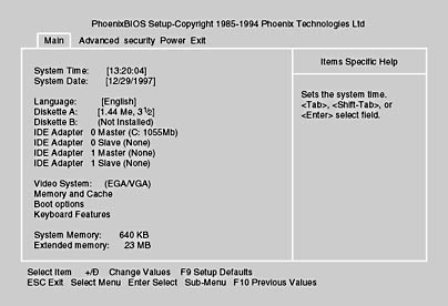
Figure 6.4 Main screen
The hard disk drive setup screen (Figure 6.5) is where individual hard drive parameters are set. Today, most hard drives based on IDE (Integrated Device Electronics) can be automatically detected by the BIOS. The CMOS settings are then made by the BIOS automatically. However, you should still know how to do this manually, to be able to work with an older machine and in case the setup program fails in its recognition.
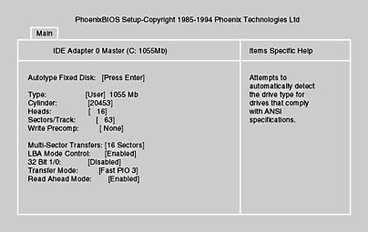
Figure 6.5 Hard disk drive setup screen
The Advanced screen (Figure 6.6) leads to more advanced setup parameters. A lot of customization can be achieved using these settings. Pay careful attention to any warnings that come up before you make any changes to device settings. If you don't understand a setting, it is best to leave it on the default option.
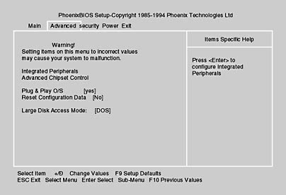
Figure 6.6 Advanced screen
The Security screen allows you to set security parameters. Be careful: once you set a password, you have to remember that password to change the security parameters. If you encounter a situation in which an owner has set and forgotten a password, you will have to flush and reset the CMOS to the factory default settings. Check the motherboard manual for information on how to do this. It usually involves changing jumper settings twice.
Notice in Figure 6.7 that the virus check reminder option is disabled. If you find a CMOS virus checker enabled, turn it off. This is especially important during operating system and program installation. If you are certain that no virus software is on the computer, yet you continue to get error messages warning you to turn off all antivirus software, the CMOS virus checker is the source of these erroneous messages. If you find this happening, disable the CMOS virus checker. Of course, if you still get the message you should check for a real virus. Figure 6.7 shows a Security screen.
TIP
These built-in CMOS virus checkers actually do very little to protect your system. For the best possible protection against viruses, be sure to install a good Windows 95 or 98 antivirus program and update it regularly.
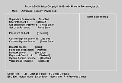
Figure 6.7 Security screen
The Power screen, shown in Figure 6.8, allows the user to set up any power conservation options provided by the manufacturer. These features typically include setting a time limit for reducing power to the monitor and hard disk drive.
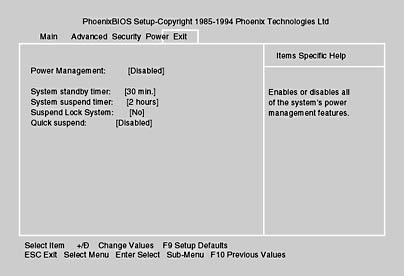
Figure 6.8 Power screen
Maintaining CMOS
Losing CMOS information is, unfortunately, a common problem. If the information on the CMOS chips is erased or corrupted, the computer will not be able to boot and/or you'll get nasty-looking errors. Some of the more common reasons that CMOS data is lost include the following:
- The on-board battery has run out.
- Cards have been removed or inserted without regard to preventing ESD.
- Improper handling of the motherboard has caused electrical short circuits or failure due to ESD.
- Something has been dropped on the motherboard.
- There is dirt on the motherboard.
- The power supply is faulty.
- There have been electrical surges.
The following types of errors indicate lost or corrupt CMOS data:
- CMOS configuration mismatch
- CMOS date/time not set
- No boot device available
- CMOS battery state low
- Cannot locate hard disk drive or floppy disk drive
It is wise to back up the CMOS setup just as you back up important data. One way to do this is to write down the information (especially before making hardware changes). There are many third-party CMOS save-and-restore utility programs available.
NOTE
Many newer machines that run Windows 95 and 98 and offer Plug and Play place less emphasis on the CMOS. The BIOS information is stored with the device and is automatically detected at boot.
The CMOS Battery
The CMOS chip requires a small trickle voltage from a battery to keep its memory alive. When the battery gets low or runs out of current, the computer will experience a sudden memory loss and thus lose settings. It might not be able to find the floppy disk or first hard disk drive and therefore signify an error indicating that it cannot find the system or non-system disk.
The voltage of CMOS batteries ranges from 3 to 6 volts. Check the motherboard or the motherboard documentation to determine the actual battery requirements. Batteries come as either on-board (NiCad batteries, soldered in place or in a fixture, that last from five to seven years) or external (nonrechargeable AA alkaline batteries that last from two to four years). The 3-volt lithium watch battery is becoming very popular with motherboard suppliers. Many of these are mounted in a special holder so that the battery can be easily changed; however, some manufacturers solder them in place.
The first clue that the battery is weakening is that the CMOS clock begins to slow down. Go to a C prompt and type time. If you notice the clock is slow, it's time to change the battery.
NOTE
Remember that an MS-DOS machine (this includes one running Windows 95 or 98) uses the CMOS clock only to get the date upon startup. After the computer is running, MS-DOS uses the memory refresh timer on the memory controller to keep time. This works well, but because the refresh timer is not very accurate about seconds, you will lose one or two seconds per day. If you never turn off a computer, it could lose time. Do not confuse this with a bad battery. When you reboot, the computer will update itself to the correct time from the CMOS. If the CMOS battery is low, it will still show the incorrect time.
When the CMOS battery dies completely, you will get lost CMOS errors, as previously described. If you reload the CMOS data and the errors return, you must change the battery. Although the computer will hold CMOS information during the week, sometimes, over the weekend—when the computer is turned off for two days—the CMOS data will be lost. Do not let these seemingly "intermittent" problems fool you. And sometimes, before a battery dies, but after it has started to fail, it will still be able to hold CMOS settings for a short time after the computer is off. Any time a computer loses the CMOS information more than once in a week, replace the battery immediately—if only to eliminate the battery as the source of the problem. After replacing the battery, you must run the setup utility and restore any CMOS settings.
NOTE
The CMOS chip contains a capacitor that allows replacement of the battery without losing data. For motherboards with soldered on-board batteries, there is usually a connection that allows you to add an external battery to replace a worn-out internal one. Be sure that the external battery has the same voltage as the on-board battery you are replacing. Some of the older PCs use a battery pack with four AA cells or a single nine-volt battery. These should be replaced with a special PC battery pack to ensure longer life.
The best source of information about replacing a CMOS battery is the documentation that comes with the motherboard.
Today's computers are becoming less reliant on battery backup for CMOS. With Windows 95 and 98 and Plug and Play technology, devices come with their own BIOS, which the system reads each time the computer is booted. This does not eliminate the need for CMOS or batteries, but it minimizes the impact of a battery failure. At the very least, you will still need to retain the date-and-time information.
All Other Chips
It would be impossible to put all the necessary BIOS information for every conceivable piece of hardware on one chip. It would also be impractical, as new devices are released almost monthly. Upgrading a machine would require a new BIOS chip (or a new version of the flash BIOS) every time. Fortunately, there are other ways to handle this challenge.
ROM Chips with BIOS
BIOS can be put on the hardware device itself. Many new add-on boards such as display adapters, network interfaces, and sound cards have their own on-board ROM chip. Since the system BIOS doesn't have a clue about how to talk to the device, this card brings its own BIOS.
Loading Device Drivers
Did you ever wonder why (almost) every newly purchased device comes with an installation disk? Did you ever notice the line(s) DEVICE= in the CONFIG.SYS file (a text file found in the root directory of the hard disk drive) or how often a program writes information to Windows 98 or 2000 Registry?
Using device drivers is the most popular way to provide BIOS support for hardware. A device driver is a program that acts as an interface between the operating system and the control circuits that operate the device. For example, Windows has "generic" code that opens a file, but the driver for the disk drive takes care of low-level tasks like positioning the read head, reading or writing blocks of data, and so on. Thus, applications programmers don't usually have to worry about these details and can assume that any hardware supported by a device driver will work. Every time the computer is booted up, the CONFIG.SYS file is read and the device drivers are loaded from the hard disk drive into RAM.
Some examples of device drivers in CONFIG.SYS are:
DEVICE=C:\DOS\HIMEM.SYS DEVICE=C:\DOS\EMM386.EXE NOEMS DEVICEHIGH =C:\SCSI\ASPIPP3.SYS /D /Z DEVICEHIGH =C:\DOS\DRVSPACE.SYS DEVICEHIGH =C:\CDROM\MTMCDAI.SYS /L=001 |
Loading device drivers in CONFIG.SYS is a requirement for machines running MS-DOS. The Windows 95, 98, and 2000 operating systems have their own drivers that are loaded as part of startup. (Drivers are covered in more detail in Chapter 15, "Software: MS-DOS and Windows 3.x," and Chapter 16, "Windows 95 and Beyond.") Occasionally, drivers become outdated or have problems. You can obtain new drivers directly from the device manufacturer (frequently from their Web sites).
NOTE
Even hardware that installs without a setup disk can be changing the registry if it is a Plug and Play device that is recognized by the operating system. Erratic problems can occur if a device is improperly identified. Under Windows 95, 98, or 2000, check under the System section of Control Panel to identify possible conflicts.
POST—Power-On Self Test
Every time a PC is turned on or reset using the Reset button or Windows Restart command, the computer is rebooted and reset to its basic operating condition. The system BIOS program starts by invoking a special program (stored on a ROM chip) called the POST (power-on self test). The POST sends out standardized commands that check every primary device (in more technical terms, it runs an internal self-diagnostic routine).
The POST has two stages:
- Test 1 occurs before and during the test of the video.
- Test 2 occurs after the video has been tested.
This division determines whether the computer will display errors by beeping or showing them on the screen. The POST does not assume the video works until it has been tested. The POST does assume that the speaker always works, but in order to let you know that the speaker is working, all computers beep on startup. Depending on the BIOS type, the POST might also sound a single beep when it's done, to let you know the boot process was successful. If something goes wrong, the POST sends a series of beep codes to let you know what the problem is or where to start looking for it.
Beep Codes Before and During the Video Test
The purpose of the first POST test is to check the most basic components. The exact order, number of tests, and error states will vary from product to product. In a healthy system, the POST reports by using a series of beep codes and screen messages to convey that all components are working. Then it transfers control to the boot drive, and the operating system is loaded. The POST is a good indication that the hardware is in working order.
If a problem occurs, the POST routine attempts to report the problem. This is also done by beep codes and (if possible) screen prompts. Some error codes are specific to chip sets or custom products, and the exact message and its meaning can vary from system to system. (See the POST code references in the system manual that shipped with the PC or the motherboard to obtain references for detailed error messages and beeps.) The following table lists the basic beep codes for AMI and Phoenix BIOSs.
| Number of Beeps | Possible Problem |
|---|---|
| 1 | DRAM refresh failure |
| 2 | Parity circuit failure |
| 3 | Base 64 KB or CMOS RAM failure |
| 4 | System timer |
| 5 | Processor failure |
| 6 | Keyboard controller or Gate A20 error |
| 7 | Virtual mode exception error |
| 8 | Display monitor write/read test failure |
| 9 | ROM BIOS checksum error |
| 10 | CMOS RAM shutdown register failure |
| 1 long, 3 short | Conventional/extended memory test failure |
| 1 long, 8 short | Display test and display vertical and horizontal retrace test failure |
Troubleshooting After a Beep
After a beep code has been recognized, there are a few things you can do to troubleshoot the error. The following table suggests some solutions. Keep in mind that in many cases it can be less expensive to replace the motherboard than to replace a chip.
| Problem | Solution |
|---|---|
| RAM refresh failure Parity error RAM bit error Base 64-KB error | Reseat and clean the RAM chips. Replace individual memory chips until the problem is corrected. |
| 8042 error (keyboard chip) Gate A20 error | Reseat and clean keyboard chip. Check operating system. Replace keyboard. Replace motherboard. |
| BIOS checksum error | Reseat ROM chip. Replace BIOS chip. |
| Video errors | Reseat video card. Replace video card. |
| Cache memory error | Reseat and clean cache chips. Verify cache jumper settings are correct. Replace cache chips. |
| Any other problems | Reseat expansion cards. Clean motherboard. Replace motherboard. |
NOTE
Many computers will generate beep codes when the only problem is a bad power supply! Turn the computer off and on three or four times to see if the same beep code is generated every time. If so, it's probably a legitimate beep code that concerns the hardware and not the power supply.Since early 1996, some BIOS programs have eliminated many beep codes. However, beep codes can still be found as part of the A+ Certification exam.
Error Messages—After the Video Test
After successfully testing the video, the POST will display any error messages on the screen. These errors are displayed in one of two ways: numeric error codes or text error messages.
Numeric Error Codes
When a computer generates a numeric error code, the machine locks up and the error code appears in the upper-left comer of the screen. The following table lists some common numeric error codes, but it is a good idea to check the manual before beginning repairs based on a beep code or error message.
| Error Code | Problem |
|---|---|
| 301 | The keyboard is broken or not plugged in. |
| 1701 | The hard disk drive controller is bad. |
| 7301 | The floppy disk drive controller is bad. |
| 161 | The battery is dead. |
| 1101 | The serial card is bad. |
Text Error Codes
BIOS manufacturers have stopped using numeric error codes and have replaced them with about 30 text messages. Instead of numbers, you get text that is usually, but not always, self-explanatory.
How Bad Is It?
There are two levels of error codes during POST: fatal and nonfatal. As the name implies, fatal errors will halt the system without attempting to load the operating system. Memory problems or a faulty disk or display adapter are examples of fatal errors. Nonfatal errors like a "missing" floppy disk drive will still result in the system attempting (and often succeeding) to load the operating system.
In most cases, the POST procedure does a good job of testing components. If it gives a clean bill of health to the hardware, its failure to boot will often lie in the operating system. You can use a bootable floppy disk in most cases to access the hard disk drive, or boot Windows using the Safe Start approach (press the F8 key just after the POST completes) and check for conflicting settings.
POST Cards
More difficult to resolve is a hardware problem that keeps the POST from issuing any report at all. When you face one of these, you will find that this is where a POST card earns its keep. These special diagnostic expansion cards monitor the POST process and display all codes (usually in two-digit hexadecimal format) as the system runs the POST. The technician can then decode this information using the manufacturer's manual. More advanced models can also be used to run advanced series of tests to isolate erratic problems.
When choosing a POST card, be sure that it will work with the types of machines you plan to test. Most are based on the ISA slot and work with most Intel CPUs. That means they should help with AT and later-based PCs that use the x86 processors. Basic models give only POST codes. More advanced models also can check DMA (direct memory access), IRQ (interrupt request), and port functions. Some come with fancy diagnostic software. The more features, the higher the price tag. But a POST card will save a lot of time and frustration, making it a worthwhile addition to any PC toolkit.
Lesson Summary
The following points summarize the main elements of this lesson:
- Understanding ROM BIOS is key to keeping a computer up and running.
- CMOS setup defines the data a computer needs to communicate with its hardware (such as its drives).
- The CMOS battery maintains BIOS data when computer power is turned off.
- POST cards can quickly repay their expense by helping to isolate problems when the POST routine fails to provide a report.
EAN: N/A
Pages: 127