Tool 72: Facility Layout Diagram
| AKA | N/A |
| Classification | Changing/Implementing (CI) |
Tool description
A facility layout diagram displays floor layouts, manufacturing or service process flows, employee movement, possible bottlenecks, excessive cycle time, and other possible inefficiencies in the present layout. This tool prepares a layout of equipment, work areas, and storage areas useful in work flow analysis (WFA) and improvement efforts.
Typical application
-
To create a floor plan of the facility for tracing employee movement.
-
To identify possible co-location of activities and shorter distances of required movement.
-
To map process flows and loopbacks.
Problem-solving phase
| → | Select and define problem or opportunity |
| → | Identify and analyze causes or potential change |
| → | Develop and plan possible solutions or change |
| Implement and evaluate solution or change | |
| Measure and report solution or change results | |
| Recognize and reward team efforts |
Typically used by
| Research/statistics | |
| Creativity/innovation | |
| 2 | Engineering |
| Project management | |
| 3 | Manufacturing |
| Marketing/sales | |
| 4 | Administration/documentation |
| Servicing/support | |
| Customer/quality metrics | |
| 1 | Change management |
before
-
Process flowchart
-
Cycle time flowchart
-
Opportunity analysis
-
Mental imaging
-
Interview technique
after
-
Work flow analysis (WFA)
-
Activity analysis
-
Variance analysis
-
Potential Problem Analysis
-
What-if analysis
Notes and key points
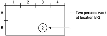
For easy reference to any work area, use grid labeling of facility layout. Example:
Step-by-step procedure
-
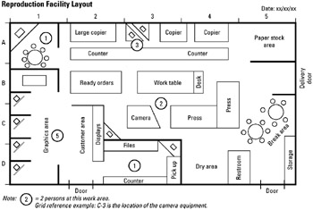
STEP 1 First, identify and observe the facility or work area for the normal work flow, equipment location, and the number of employees normally assigned to workstations. See example Reproduction Facility Layout.
-
STEP 2 Using drafting paper, prepare a facility layout diagram showing all major items or equipment, furniture, and other objects or areas of interest.
-
STEP 3 Name all drawn items, complete grid reference labeling, and identify the number of people working at certain locations.
-
STEP 4 Finally, check for accuracy and date the diagram.
Example of tool application
EAN: 2147483647
Pages: 326