Introduction to Layer 3 Switching
| In the previous chapter, you were introduced to the concept of inter-VLAN routing, which is required to enable hosts that belong to different VLANs on the same LAN network to communicate with each other. Implementing inter-VLAN routing introduces several benefits, which include the following:
Of course, all of these features must be provided with a very important caveatinter-VLAN routing should not affect performance, as users expect high performance from the LAN. A popular approach to providing the benefits of inter-VLAN routing and also ensuring the performance of the LAN is not degraded has been to implement Layer 3 switches, which are essentially Layer 2 switches with a routing engine that is designed to specifically route traffic between VLANs in a LAN environment. Using Layer 3 switches for inter-VLAN routing as opposed to traditional routers is popular (and recommended) for the following reasons:
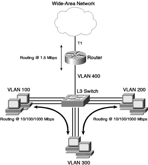
Layer 3 switching is cheap because Layer 3 switches are targeted specifically for inter-VLAN routing, where only Ethernet access technologies are used in high densities. This makes it easy for Layer 3 switch vendors such as Cisco to develop high performance Layer 3 switches, as vendors can develop hardware chips (known as application-specific integrated circuits or ASICs) that specifically route traffic between Ethernet networks, without having to worry about the complexities of also supporting WAN technologies such as Frame Relay or ATM. Routing over WAN networks can still be supported, simply by plugging a traditional router that connects to the WAN networks into the LAN network. Figure 6-1 illustrates the concept of Layer 3 switching. Figure 6-1. Layer 3 Switching
In Figure 6-1, a L3 switch provides switched LAN connections for each device in the network. Three user VLANs are present, and a routing engine on the L3 switch enables communications between each VLAN. The L3 switch possesses specialized hardware chips called application-specific integrated circuits (ASICs) that are preprogrammed and designed to route between Ethernet ports at high speed. A traditional router is connected to the L3 switch and handles the routing of any traffic that needs to be sent across the WAN. Because the L3 switch does not need the flexibility required of the router to support different WAN protocols, it can use ASICs to route traffic at the 100-Mbps speeds expected of the LAN network. The router in the network is designed to handle the requirements of routing at T1 (1.5 Mbps) speeds and would cause a bottleneck if it had to route between VLANs, as routing is performed in software, not hardware. Of course, you could purchase an expensive high-performance router with three Ethernet ports and a T1 interface; however, the cost associated with this approach is much higher. The cost associated with adding more routed Ethernet ports to the router (e.g., if a new VLAN was added to the network) is also high. Layer 3 Routing Versus Layer 3 SwitchingIt is important to understand the difference between Layer 3 routing and Layer 3 switching. Both terms are open to some interpretation; however, the distinction between both can perhaps be best explained by examining how an IP packet is routed. The process of routing an IP packet can be divided into two distinct processes:
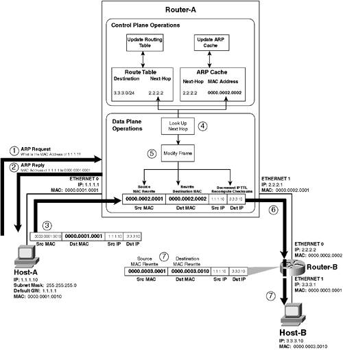
Figure 6-2 illustrates the differences between control plane operation and data plane operation by providing an example of how an IP packet is routed. Figure 6-2. Control Plane and Data Plane Operation
NOTE Some Cisco Catalyst Layer 3 switches support the Layer 3 switching of Internetwork Packet Exchange (IPX) packets as well. For this chapter, the discussion focuses purely on IP packets. In Figure 6-2, Host-A is sending an IP packet to Host-B over a LAN network that includes a couple of routers. The following describes the events that occur in Figure 6-2.
NOTE It is important to understand that the MAC addresses are specific only to each local LAN. For example, Host-A does not know and does not need to know Host-B's MAC address or even Router-B's MAC address. Host-A needs to know only the MAC address of Router-A so that it can deliver IP packets in Ethernet frames locally to Router-A, with Router-A then forwarding the packet on appropriately and with this process occurring on a hop-by-hop basis until the final destination is reached. Control Plane and Data Plane ImplementationControl plane operations require an understanding of routing protocols and hence require some intelligence that is capable of supporting the complex algorithms and data structures associated with protocols such as Open Shortest Path First (OSPF) and Border Gateway Protocol (BGP). Depending on the routing protocol(s) configured, the control plane operations required might vary dramatically between different routing devices. On the other hand, data plane operations are simple and fixed in their implementation because how a packet is routed is the same, regardless of the routing protocol that was used to learn where a packet should be routed. Although data plane operations are simple, they are also performed much more frequently than control plane operations because data plane operations must be performed for every packet that is routed, while control plane operations must be performed only for routing topology changes once the routing table is built. This means that the performance of the data plane implementation ultimately dictates how fast a routing device can route packets. Because control plane operations are complex, most vendors use a general purpose CPU capable of supporting a high-level programming language so that vendors can easily develop and maintain the complex code associated with support the various routing protocols. In this respect, the control plane is implemented in software, which means that code (software) developed from a high-level programming language provides control plane operation. Both traditional routers and Layer 3 switches normally take the same approach to implementing the control plane operations associated with IP routing, using software that requires a general purpose CPU. In contrast to control plane operations, data plane operations are very simple. In fact, the data plane operations required can be presented in a single table. Table 6-1 describes the data plane operations that must take place, assuming a packet is addressed from a host called Host-A to another host called Host-B and is sent via a router.
In Table 6-1, the details of the received frame are indicated and then the details required for the rewritten frame that is transmitted after routing are shown. Notice that the following fields must be modified for the rewritten frame that is forwarded to the next hop routing device:
The process of how the data plane operations shown in Table 6-1 are implemented is where the difference between a traditional router and Layer 3 switch lie. A traditional router uses the same general purpose CPU used to perform control plane operations to also implement data plane operations, meaning data plane operations are handled in software. A Layer 3 switch on the other hand uses an ASIC to perform data plane operations because it is very easy to program the very simple operations required for the data plane into an ASIC. In this respect, the data plane is implemented in hardware because a series of hardware operations are programmed into the ASIC that perform the data plane operations required for routing a packet. NOTE It should be noted that many high-end routers use ASICs for data plane operations in a similar fashion to Layer 3 switches. In fact, much of the ASIC technology used in Layer 3 switches is derived from the ASICs used in high-end routers. So how does this affect performance? Well, a general purpose CPU is designed to support many different functions, where as an ASIC is designed to support a single function or a handful of specific functions such as performing the data plane operations required to route a packet. This means that an ASIC can operate much faster because the internal architecture of the ASIC can be optimized just to perform the operations required for data plane operations, whereas a general purpose CPU must be designed to support a series of generic functions that do not relate to data plane operations whatsoever (as the CPU must support other applications). A high-level language combines the generic functions of the general purpose CPU to provide the higher specific functions required to perform data plane operations. This approach allows flexibility but comes at the price of performance. Hence, a Layer 3 switch that performs data plane operations using ASICs route packets much faster than a traditional router that performs data plane operations using a general purpose CPU. NOTE The term software when applied to Layer 3 routing means that a general purpose CPU performs routing, along with other tasks such as system maintenance and providing command-line access. The term hardware when applied to Layer 3 switching means an ASIC dedicated to the process of Layer 3 switching, whose sole purpose in life is to route packets. Hardware-Based Layer 3 Switching ArchitecturesAlthough the data plane operations required for routing IP packets can easily be accelerated by the use of ASICs, it is important to understand that a fundamental requirement for data plane operation is the process of determining the next hop IP address for the destination IP address of the packet and the MAC address associated with the next hop so that the correct destination MAC address can be written to the rewritten frame. The components that implement data plane operations must "look up" this information (see the lookup operation in Figure 6-2); this lookup operation in itself can become a bottleneck. To ensure the lookup process does not significantly delay the rewrite processes of data plane operation, Layer 3 switches use specialized data structures that allow for fast lookups. These data structures can be split into two categories:
It is important to note that in addition to possessing a high performance lookup mechanism, many Layer 3 switches also possess specialized hardware that can be used to provide QoS classification and security access control (using access control lists) for packets at the same time the next hop lookup is being implemented. This means that these features can be turned on with affecting performance. | ||||||||||||||||||||||||||||||||||||||||||||||||||
EAN: 2147483647
Pages: 135
- Assessing Business-IT Alignment Maturity
- Linking the IT Balanced Scorecard to the Business Objectives at a Major Canadian Financial Group
- A View on Knowledge Management: Utilizing a Balanced Scorecard Methodology for Analyzing Knowledge Metrics
- Measuring ROI in E-Commerce Applications: Analysis to Action
- Governance Structures for IT in the Health Care Industry