Multilayer LAN Design
| In the previous section, inter-VLAN routing architectures were discussed; however, the discussion was not based around how to split a LAN topology into VLANs and where you apply inter-VLAN routing. These issues delve into the topic of LAN design, where to are required to implement a LAN infrastructure that exhibits certain characteristics:
Today, Two popular approaches exist when it comes to LAN design:
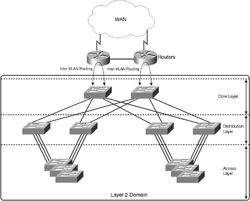
When evaluating each design approach, you must consider each of the characteristics described previously and how the design meets the requirements of each of those characteristics. Each of the design approaches is now discussed, with reference to the previous characteristics to allow comparison of the two models. Collapsed Backbone DesignThe collapsed backbone architecture is the original LAN design methodology that includes inter-VLAN routing. In this design, the entire LAN infrastructure is configured as a Layer 2 domain with one or more VLANs. Because the Layer 2 domain spans the entire network, the collapsed backbone architecture is commonly referred to as being flat. To route between VLANs, a router installed in a router-on-a-stick configuration is attached at the edge of the network, allowing devices in different VLANs to communicate. Figure 5-3 demonstrates a collapsed backbone design. Figure 5-3. Collapsed Backbone
In Figure 5-3, the entire LAN topology is a single Layer 2 domain, with two routers attached to the LAN in a router-on-a-stick configuration. The network in Figure 5-3 is redundantwithin the Layer 2 domain, spanning tree is used to build a loop-free topology, detect failures, and converge the network to a working topology should a failure occur. The routers are normally configured with a protocol such as Hot Standby Router Protocol (HSRP) to provide a single virtual router that can be serviced by either router (HSRP is discussed later in this chapter). Multiple VLANs can be configured within the Layer 2 domain; however, to enable inter-VLAN communication, routing is required. The connection between the core switches and the routers are normally trunks, transporting traffic from VLANs within the Layer 2 domain for inter-VLAN routing. All traffic that requires inter-VLAN routing must be sent through the core of the network to the routers, and then back again. In a sense, each VLAN collapses onto one or more backbone routers, which provide inter-VLAN routing, as well as connectivity to the WAN. Collapsed backbone architectures have some flaws, which are generally related to the scalability of the network. As a collapsed backbone architecture grows, the size of the Layer 2 domain grows. This has several consequences:
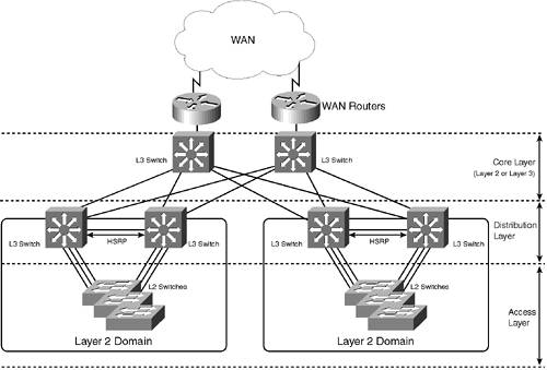
As you can see in the next section, a multilayer design addresses many of the issues discussed above. Multilayer DesignA multilayer design is hierarchical in nature, with the network separated into modular layers and with routing enabled for traffic sent between each layer. Instead of operating a single, large, flat Layer 2 domain, a multilayer design breaks up the network into smaller, more manageable Layer 2 domains at the edge of the network, and then relies on IP routing at the core of the network to route traffic between edge devices. Figure 5-4 demonstrates a multilayer design. Figure 5-4. Multilayer Design
In Figure 5-4, the LAN topology is separated into multiple Layer 2 domains by introducing routing at the distribution and core layers. The core layer can be a Layer 2 or Layer 3 core. If a Layer 2 core is used, another Layer 2 domain is formed that encompasses the distribution layer switches and the core. Notice that the size of each Layer 2 domain is significantly reduced, which means the associated delays with spanning-tree convergence can be reduced because of the smaller network diameter. Even if you implement a Layer 2 core, you have still segmented the LAN into several smaller Layer 2 domains, allowing for scalability and reduced reliance on spanning tree for convergence. NOTE It is recommended to implement a Layer 3 core, especially for larger networks where you need maximum scalability and availability. However, many networks will implement a Layer 2 core because of the lower costs associated with such a design. If you implement a Layer 3 core, only consider spanning-tree convergence issues at the access layer. Notice that the access layer, Layer 2 domains suit a spanning-tree UplinkFast configuration, where each access layer switch is configured with UplinkFast to enable fast convergence (in the order of a few seconds) in the event of a distribution layer switch failure. This means that the delays associated with spanning-tree convergence are minimal compared with the delays incurred on a collapsed backbone design. Load sharing can also be introduced at the access layer over each redundant uplink by altering spanning-tree costs associated with each uplink on a per-VLAN basis. At the distribution layer, routing is provided that enables inter-VLAN routing between VLANs configured within the Layer 2 domain that comprises the access layer, as well as connectivity to the core of the network. Because the access layer contains end devices, such as PCs, servers, and printers, these devices will normally be configured with a default gateway pointing towards the distribution layer. To provide default gateway redundancy, HSRP (discussed in the next section) can be used to protect against the failure of a single distribution layer switch. The core of the network can be either a Layer 2 core, based upon Ethernet or Asynchronous Transfer Mode (ATM), or a Layer 3 core. With a Layer 2 Ethernet core, the core is a Layer 2 domain and uses spanning tree as the protocol to provide redundancy and load sharing. The core of the network is typically limited to a few devices so the issues with spanning tree seen in a collapsed backbone architecture are not normally experienced with a Layer 2 core in a multilayer design. With a Layer 3 core, dynamic routing protocols are used to control traffic flows through the core and provide failure detection. Modern dynamic routing protocols, such as Open Shortest Path First (OSPF) and Enhanced IGRP (EIGRP) provide much more intelligent failure detection mechanisms than the spanning-tree mechanisms used in a collapsed backbone LAN, resulting in reduced convergence in the event of a network failure. Dynamic routing protocols also can load share traffic on a more granular basis than spanning tree, increasing the performance and efficiency of the network. In summary, today for most modern networks, the collapsed backbone architecture is rapidly being replaced with a multilayer topology for the following reasons:
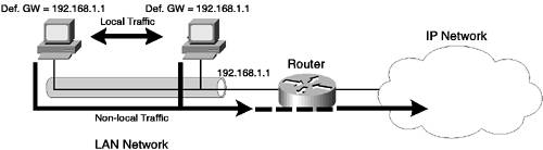
Hot Standby Router ProtocolHot Standby Router Protocol (HSRP) is a protocol designed to provide redundancy for the routing services provided to the access layer or edge components of a multilayer LAN topology, where end devices, such as servers and workstations, connect to the network. NOTE HSRP is a topic that you must understand and be able to configure for the CCNP LAN Switching examination; hence, its coverage here and later on in Scenario 5-3. HSRP is designed to provide Layer 3 redundancy where dynamic routing protocols, which support the ability to detect failures in the network and reroute traffic over a redundant path, cannot be used. End devices located at the edge of the network typically do not participate in dynamic routing protocols because they are designed for end-to-end communications rather than the delivery of those communications. This means that end devices typically are configured with a default gateway, which represents a routing device that handles all traffic destined for a system located remotely, offloading the task of routing traffic to a destination over the appropriate path in the network. For example, a host might have an IP address of 192.168.10.100 with a subnet mask of 255.255.255.0 and a default gateway of 192.168.10.1. If the host needs to communicate with a host on the same subnet (for example, 192.168.10.200), the host communicates directly. If the host needs to communicate with a host on a different subnet (for example, 192.168.20.100), then packets are sent to the default gateway, and the default gateway is responsible for routing the packet to its correct destination. Figure 5-5 demonstrates this simple concept. Figure 5-5. Routing Using Default Gateways
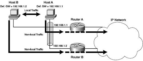
In Figure 5-5, the hosts on the LAN can reach the rest of the IP network via only one devicethe locally attached router. If each host has the locally attached router (192.168.1.1) configured as the default gateway, all non-local traffic is sent to the router. Once the router receives the traffic, it and the other routers that lead to the final destination are responsible for ensuring that the packets sent reach their destination via the best path through the network. Referring to Figure 5-5, if the default gateway fails for some reason, the hosts connected to the gateway are not able to communicate with the rest of the network. To implement redundancy, a second default gateway can be introduced. Figure 5-6 shows an example topology with two default gateways servicing a single VLAN. Figure 5-6. Using Two Default Gateways
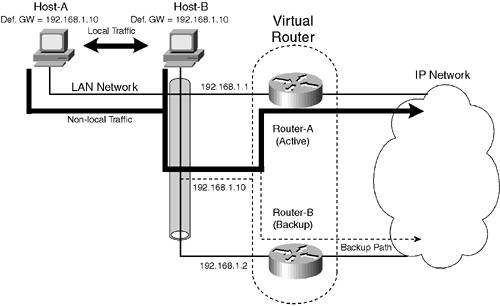
In Figure 5-6, a second router (Router B) has been introduced that connects to the rest of the IP network. Host A is configured with Router A as its default gateway and Host B is configured with Router B as its default gateway. Consider what happens when Router A fails. Because Host A is configured with Router A as its default gateway, Host A attempts to send any non-local traffic to Router A, which fails because Router A is down. To alleviate this, you can configure Host A with a new default gateway of Router B; this configuration solves the problem, but requires manual reconfiguration on each end device. You can also configure two default gateways (Router A and Router B) on each end device; however, most operating systems implement crude mechanisms for detecting a default gateway failure and switching to an alternate default gateway, making such mechanisms unreliable. For example, Microsoft operating systems require a reboot for an alternate default gateway to be used after the primary default gateway has gone down, which would cause disruption if the configuration of multiple default gateways were used to provide redundancy. Clearly, just simply installing a second gateway is not going to resolve the issue. Another approach is to install two physical default gateway devices, but allow these devices to co-operatively interact so that they can appear as a single virtual default gateway for end devices connected to the LAN. This means that each end device is configured with a single virtual IP address for the default gateway. The routers are then configured as either active or standby for the virtual IP address. The active router services all communications to the virtual IP address from end devices. If the active router fails, then the standby router steps in and services all communications to the virtual default gateway. The active and standby routers know if the other is alive by communicating periodically between each other via the network. Figure 5-7 shows the concept of using redundant routers to implement a virtual router (default gateway). Figure 5-7. The Virtual Default Gateway
In Figure 5-7, Router-A and Router-B are configured to present a virtual router to the LAN network, which possesses a virtual IP address (192.168.1.10) that is configured as the default gateway on each host attached on the LAN. A virtual MAC address also exists for the virtual IP address, which is required to enable Layer 2 communications between end devices and the virtual router. In terms of physical operation, one of the physical routers (assume Router-A) is the active router, servicing the communications to the virtual IP address and MAC address from the hosts. Notice the path that packets take through the network while Router-A is operational (represented by the solid arrow). Each IP packet is encapsulated in Ethernet frames, which are addressed to the virtual MAC address. The active router listens for frames with the virtual MAC address, receipting these frames and then routing the packet contained within the frame towards the destination IP address of the packet. If the active router (Router-A) fails, then the backup router (Router-B) starts servicing the communications to the virtual IP address and MAC address, with the dashed arrow in Figure 5-7 showing the new path packets take in the network. The hosts on the network believe they are always communicating through the virtual router (represented by the dashed line) and do not know that a physical router has failed because they are still talking to the same virtual IP address and another physical router services the virtual IP address in the event of a failure. Router-A and Router-B use a protocol to periodically communicate with each other; this protocol serves as a mechanism to detect if a router fails, as communications will cease from the remote router. Two common protocols are used to implement the concept of the virtual router, as shown in Figure 5-7:
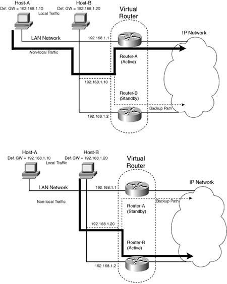
The use of HSRP is very common in Cisco-only topologies, and to date only high-end Cisco routers support VRRP. Given that you normally implement two identical routing devices to implement HSRP or VRRP, if you are using Cisco routers, no benefits in using VRRP exist. It is important to note that neither HSRP nor VRRP provides load sharing as a function. Both technologies are active/standby technologies, where a single active router always services the virtual IP address and a standby router services the virtual IP address only if the active router fails. For example, referring to Figure 5-7, Router-A is considered the active router and Router-B is considered the standby router. Under normal operation, all traffic flows through Router-A, leaving Router-B (and its link to the rest of the network) idle. You can implement load sharing by introducing multiple virtual IP addresses and alternating the active role between each physical router for each virtual IP address. Figure 5-8 demonstrates this concept. Figure 5-8. Using Multiple Virtual Routers for Load Sharing
In Figure 5-8, two virtual routers represented each by a virtual IP (VIP) address are configured. The top figure shows the first VIP (192.168.1.10), which is serviced by Router-A as the primary router, with Router-B acting as the standby router. The bottom figure shows the second VIP (192.168.1.20), which is serviced by Router-B as the primary router, with Router-A acting as the standby router. To enable the use of multiple VIPs to implement load sharing, half of the hosts on the network (i.e., Host-A) are configured with the first VIP (192.168.1.10) as their default gateway, and the other half of the hosts on the network (i.e., Host-B) are configured with the second VIP (192.168.1.20) as their default gateway. Although this form of load sharing might not provide equal distribution of traffic through each physical router, this ensures some form of load sharing, and both VIPs are protected against the failure of a single router. For example, if Router-A failed in Figure 5-8, Router-B would service both the 192.168.1.20 VIP, because it is configured as the active router for that VIP, and also the 192.168.1.10 VIP, because Router-A has failed and Router-B must assume the active router role for the VIP until Router-A is restored. This ensures all non-local communications continue to flow through the network. |
EAN: 2147483647
Pages: 135