Scenario Prerequisites
| To successfully commence the configuration tasks required to complete this scenario, Table 4-5 describes the prerequisite configurations required on each device in the scenario topology. Any configurations not listed can be assumed as being the default configuration.
Example 4-1 through Example 4-4 shows the prerequisite configuration required on each switch. Example 4-1. Scenario 10-1 Prerequisite Configuration for Switch-AConsole> (enable) set system name Switch-A System name set. Switch-A> (enable) set password Enter old password: ø Enter new password: ***** Retype new password: ***** Password changed. Switch-A> (enable) set enablepass Enter old password: ø Enter new password: ***** Retype new password: ***** Password changed. Switch-A> (enable) set interface sc0 192.168.1.1 255.255.255.0 Interface sc0 IP address and netmask set. Switch-A> (enable) set vtp mode transparent VTP domain modified Switch-A> (enable) set trunk 2/1 nonegotiate dot1q Port(s) 2/1 trunk mode set to nonegotiate. Port(s) 2/1 trunk type set to dot1q. Switch-A> (enable) set trunk 2/2 nonegotiate dot1q Port(s) 2/2 trunk mode set to nonegotiate. Port(s) 2/2 trunk type set to dot1q. Switch-A> (enable) set trunk 2/3 nonegotiate dot1q Port(s) 2/3 trunk mode set to nonegotiate. Port(s) 2/3 trunk type set to dot1q. Example 4-2. Scenario 10-1 Prerequisite Configuration for Switch-BSwitch# configure terminal Switch(config)# hostname Switch-B Switch-B(config)# enable secret cisco Switch-B(config)# line vty 0 15 Switch-B(config-line)# password cisco Switch-B(config-line)# exit Switch-B(config)# interface vlan 1 Switch-B(config-if)# no shutdown Switch-B(config-if)# ip address 192.168.1.2 255.255.255.0 Switch-B(config-if)# exit Switch-B(config)# vtp mode transparent Setting device to VTP TRANSPARENT mode. Switch-B(config)# interface range fastEthernet0/1 - 3 Switch-B(config-if)# switchport trunk encapsulation dot1q Switch-B(config-if)# switchport mode trunk Switch-B(config-if)# switchport nonegotiate Example 4-3. Scenario 4-1 Prerequisite Configuration for Switch-CSwitch# configure terminal Switch(config)# hostname Switch-C Switch-C(config)# enable secret cisco Switch-C(config)# line vty 0 15 Switch-C(config-line)# password cisco Switch-C(config-line)# exit Switch-C(config)# interface vlan 1 Switch-C(config-if)# no shutdown Switch-C(config-if)# ip address 192.168.1.3 255.255.255.0 Switch-C(config-if)# exit Switch-C(config)# vtp mode transparent Setting device to VTP TRANSPARENT mode. Switch-C(config)# interface range fastEthernet0/1 - 2 Switch-C(config-if)# switchport trunk encapsulation dot1q Switch-C(config-if)# switchport mode trunk Switch-C(config-if)# switchport nonegotiate Example 4-4. Scenario 4-1 Prerequisite Configuration for Switch-DConsole> (enable) set system name Switch-D System name set. Switch-D> (enable) set password Enter old password: ø Enter new password: ***** Retype new password: ***** Password changed. Switch-D> (enable) set enablepass Enter old password: ø Enter new password: ***** Retype new password: ***** Password changed. Switch-D> (enable) set interface sc0 192.168.1.4 255.255.255.0 Interface sc0 IP address and netmask set. Switch-D> (enable) set vtp mode transparent VTP domain modified Switch-D> (enable) set trunk 2/1 nonegotiate dot1q Port(s) 2/1 trunk mode set to nonegotiate. Port(s) 2/1 trunk type set to dot1q. Switch-D> (enable) set trunk 2/2 nonegotiate dot1q Port(s) 2/2 trunk mode set to nonegotiate. Port(s) 2/2 trunk type set to dot1q. After the prerequisite configuration is implemented, you should verify PING connectivity between each switch before proceeding. Configuration TasksNow that you understand the design decisions for the network topology of Figure 4-5, you are ready to actually configure the network. For this scenario you need to perform the following tasks:
Configuring the Root Bridge (Switch-A)The simplest and quickest method to configure a root bridge is to use the spanning tree root macro commands. On Switch-A (CatOS), the syntax of the spanning tree root macro is as follows: set spantree root [secondary] vlans [dia network-diameter] [hello seconds] The vlans parameter allows you to define the VLANs for which the switch becomes the root bridge. It is important to remember that by default a Cisco Catalyst switch runs a separate spanning tree instance per VLAN, meaning it may be the root bridge for one VLAN, but not for another VLAN. When you execute the root macro command (and omit the secondary parameter), the switch looks at the priority of the root bridge and ensures that the priority of the local switch is set lower, forcing the local switch to become the root bridge. If the current root bridge has a priority higher than 8192, the local priority is set to 8192. If the current root bridge has a priority less than 8192, the local priority is set to one less than the current root bridge priority. For example, if a root bridge existed with a priority of 1000, the macro sets the priority of the local switch to 999. The optional secondary parameter specifies that the root macro configures the bridge priority so that the bridge becomes a root bridge only in the event of a failure of the root bridge. NOTE The secondary keyword always sets the bridge priority to 16384. No mechanism in spanning tree allows a bridge to detect the second highest bridge priority. Even if the current priority of the root bridge is higher than 16384, the set spantree root secondary command does not take this priority into account, it merely sets the bridge priority to 16384. Always make sure your root bridge has a priority less than 16384 and that all other bridges have a priority greater than 16384. If you follow this rule, the command will always work as planned. Example 4-5 demonstrates using the spanning tree root macro command for VLAN 1 on Switch-A. Example 4-5. Configuring Switch-A as a Root Bridge Switch-A> (enable) set spantree root 1 VLAN 1 bridge priority set to 8192. VLAN 1 bridge max aging time set to 20. VLAN 1 bridge hello time set to 2. VLAN 1 bridge forward delay set to 15. Switch is now the root switch for active VLAN 1. As you can see, the bridge priority for VLAN 1 is set to 8192, which means that it becomes the root bridge (assuming there are no other switches that have a lower bridge priority, which by default is not the case). Notice that the STP timers can also be modified, although in Example 4-5 these are unchanged. Configuring the optional dia and hello parameters alters the timers, which are recalculated according to the 802.1d specification. Example 4-6 shows what happens when you configure a network diameter of 4, which is the maximum diameter of the topology shown in Figure 4-5 (e.g., Switch-D Example 4-6. Modifying STP Timers using the Macro Command Switch-A> (enable) set spantree root 1 dia 4 hello 1 VLAN 1 bridge max aging time set to 8. VLAN 1 bridge hello time set to 1. VLAN 1 bridge forward delay set to 6. Switch is now the root switch for active VLAN 1. Switch is already the root switch for active VLAN 1. Notice that the bridge priority for VLAN 1 is not modified because it has already been lowered in Example 4-1. The STP timers have now been modified from their defaults and are optimized for the topology of Figure 4-5 according to the 802.1d specification. Convergence of this network has been reduced from the default maximum of 50 seconds to a maximum of 20 seconds (max age + listening + learning). If you look at the configuration on Switch-A, you find that there is no mention of the set spantree root command. It is a macro command, which actually configures other commands automatically. The commands that are configured automatically by the macro include the following: set spantree priority priority [vlan-id] set spantree hello hello-timer [vlan-id] set spantree maxage maxage-timer [vlan-id] set spantree fwddelay fwddelay-timer [vlan-id] NOTE You can reset all STP parameters modified by the root macro to their defaults by using the clear spantree root vlan-id command. Example 4-7 demonstrates the process of configuring a root bridge and STP timers for VLAN 1 on Switch-A without using the macro command. Example 4-7. Configuring Switch-A as the Root Bridge ManuallySwitch-A> (enable) set spantree priority 8192 1 VLAN 1 bridge priority set to 8192. Switch-A> (enable) set spantree hello 1 1 VLAN 1 bridge hello time set to 1. Switch-A> (enable) set spantree maxage 8 1 VLAN 1 bridge max aging time set to 8. Switch-A> (enable) set spantree fwddelay 6 1 VLAN 1 bridge forward delay set to 6. WARNING When modifying spanning tree timers manually, ensure that you adhere to the recommendations of 802.1d specification. 802.1d defines that STP timers are calculated on network diameter and hello timer. Configuring the Secondary Root Bridge (Switch-B)On Switch-B (Cisco IOS), the syntax of the global configuration spanning tree root macro is as follows: spanning-tree vlan vlan-id root {primary | secondary} [diameter network-diameter] [hello-time seconds] As you can see, the root macro command on Cisco IOS essentially has the same configuration parameters as the CatOS equivalent. Example 4-8 demonstrates using the spanning tree root macro command to configure Switch-A as the secondary root bridge for VLAN 1. Example 4-8. Configuring Switch-B as a Secondary Root Bridge Switch-B(config)# spanning-tree vlan 1 root secondary diameter 4 hello-time 1 vlan 1 bridge priority set to 28672 vlan 1 bridge max aging time set to 8 vlan 1 bridge hello time set to 1 vlan 1 bridge forward delay set to 6 The first thing that should stand out in Example 4-8 is that the priority is set to 28672, instead of 16384, which is what the secondary root macro command sets the bridge priority to on a CatOS switch. If you configured Switch-B as the root bridge, the priority would be set to 24576, again different from the 8192 set on a CatOS switch. Many Cisco IOS switches have a feature called extended system ID enabled by default, which is a feature that extends the number of spanning-tree instances that can be supported at any one time. The extended system ID is defined in the IEEE 802.1t specification and is essentially just a subfield within the bridge priority field of the bridge ID. Figure 4-10 shows the structure of a bridge ID that uses extended system ID. Figure 4-10. Bridge ID Structure with Extended System ID
In Figure 4-10, the bottom of the figure shows that the last 12 bits of the bridge priority field are used for the extended system ID, while the 4 high-order bits are used for priority. The extended system ID feature allows a switch to support up to 4096 (212) VLANs (which equates to 4096 spanning-tree instances by default on a Cisco switch), as is required by the 802.1d and 802.1q standards, without requiring that 4096 unique MAC addresses be assigned to each switch. If you combine the values of the switch priority field and the extended system ID field, you get the traditional bridge priority value in bridge IDs that do not use extended system ID. For example, if the switch priority is configured as 32768 for VLAN 1 (therefore, the extended system ID is 1), the bridge priority field will be 32769. You can use the show spanning-tree bridge command to quickly view the bridge IDs associated with each VLAN on a switch, which is useful for illustrating the structure of a bridge ID that uses extended system ID. Example 4-9 demonstrates the use of this command on a switch with multiple VLANs. Example 4-9. Viewing the Bridge IDs for Multiple VLANs Switch-B# show spanning-tree bridge Vlan Bridge ID Time Age Dly Protocol ---------------- --------------------------------- ----- --- --- -------- VLAN0001 32769 (32768,1) 0009.b7aa.9c80 1 20 15 ieee VLAN0002 32770 (32768,2) 0009.b7aa.9c80 2 20 15 ieee When added, the switch priority and the extended system ID give the bridge ID. Notice that the same MAC address is used for each VLAN, with the extended system ID providing uniqueness for each bridge ID. NOTE Extended system ID is supported only in IOS version 12.1(8)EA or later on the Catalyst 2950 and Catalyst 3550 and is always enabled. The feature is supported on the native IOS Catalyst 6000 switch in IOS version 12.1(8)EX or later and can be enabled or disabled if the chassis supports up to 1024 MAC addresses (some chassis support only 64 MAC addresses, which means the feature cannot be disabled). At the time of this writing, the Catalyst 4000 Supervisor 3 does not support this feature because 1024 MAC addresses are allocated to each Supervisor 3. On a switch such as the Catalyst 6000, up to 1024 MAC addresses have been traditionally assigned to the switch, which has in turn required up to 1024 unique STP instances using the traditional bridge ID shown in Figure 4-10. By using the extended system ID, a switch requires only a single MAC address to ensure the bridge ID is always unique, with the extended system ID being altered for each different spanning-tree instance (VLAN) on the switch. The extended system ID is automatically assigned as the VLAN ID per STP instance on the switch, which leaves only four configurable bits (24 or 16 configurable values) for switch priority. Because of the limitation on configurable options for switch priority, using higher switch priority values (24576 and 28672 as opposed to 8192 and 16384) in the root macro command allows for greater flexibility if you need to introduce new root bridges in the future. TIP Extended system ID is known as the STP MAC Address reduction feature on CatOS. This feature is disabled by default, but is automatically enabled (and cannot be disabled) if extended range VLANs (VLAN IDs above 1024) are enabled or a small number of MAC addresses have been allocated to the switch. If you are not using extended range VLANs and the switch has a large number of MAC addresses allocated, you can enable or disable the use of extended system ID on CatOS by using the set spantree macreduction command. It is important to understand that just like CatOS, the root macro command on Cisco IOS is smart enough to detect if an existing root bridge has a priority that is lower than the normal values used by the root macro. Example 4-10 demonstrates configuring Switch-B as the root bridge for VLAN 1, with Switch-A already acting as the root bridge with a priority of 8192. Example 4-10. Configuring Switch-B as the Root Bridge with an Existing Root Bridge Switch-B(config)# spanning-tree vlan 1 root diameter 4 hello-time 1 vlan 1 bridge priority set to 4096 vlan 1 bridge max aging time unchanged at 8 vlan 1 bridge hello time unchanged at 1 vlan 1 bridge forward delay unchanged at 6 Notice that because Switch-A has a priority of 8192, Switch-B chooses the next lowest priority value. The next lowest value is 4096 (not 8191 as you might expect), because Switch-B is using the extended system ID feature, which means that switch priority can be modified only in increments of 4096. After using the spanning tree macro command on Switch-B, if you look at the running configuration, you find that there is no mention of the spanning-tree vlan 1 root command. It is a macro command, which actually configures other commands automatically. The commands that are configured automatically by the macro include the following global configuration mode commands: spanning-tree vlan vlan-id priority priority spanning-tree vlan vlan-id hello-time hello-timer spanning-tree vlan vlan-id max-age maxage-timer spanning-tree vlan vlan-id forward-time fwddelay-timer Example 4-11 demonstrates the process of configuring a secondary root bridge and STP timers for VLAN 1 on Switch-B without using the macro command. Example 4-11. Configuring Switch-B as the Secondary Root Bridge ManuallySwitch-B# configure terminal Switch-B(config)# spanning-tree vlan 1 priority 28672 Switch-B(config)# spanning-tree vlan 1 hello-time 1 Switch-B(config)# spanning-tree vlan 1 max-age 8 Switch-B(config)# spanning-tree vlan 1 forward-time 6 Verifying the Root BridgeOn Switch-A, to verify that it is the root bridge for VLAN 1, you can use the show spantree 1 command, as demonstrated in Example 4-12. Example 4-12. Verifying the Root Bridge on Switch-A Switch-A> (enable) show spantree 1 VLAN 1 Spanning tree mode PVST+ Spanning tree type ieee Spanning tree enabled Designated Root 00-01-96-a0-2c-00 Designated Root Priority 8192 Designated Root Cost 0 Designated Root Port 1/0 Root Max Age 8 sec Hello Time 1 sec Forward Delay 6 sec Bridge ID MAC ADDR 00-01-96-a0-2c-00 Bridge ID Priority 8192 Bridge Max Age 8 sec Hello Time 1 sec Forward Delay 6 sec Port Vlan Port-State Cost Prio Portfast Channel_id ------------------------ ---- ------------- --------- ---- -------- ---------- 1/1 1 forwarding 4 32 disabled 0 1/2 1 not-connected 4 32 disabled 0 2/1 1 forwarding 19 32 disabled 0 2/2 1 forwarding 19 32 disabled 0 ... (Output Abbreviated) ... In Example 4-12, you can see that the designated root (root bridge) has a bridge ID 8192.0001.96a0.2c00, which matches the local bridge ID shown, as indicated by the Bridge ID MAC ADDR and Bridge ID Priority fields. This bridge ID means that Switch-A is the root bridge for VLAN 1. The root priority is configured as 8192, and the spanning-tree timers are optimized for the topology of Figure 4-5. Notice that Switch-A lists the designated root cost as 0 (which makes sense because Switch-A is the root bridge) and the root port as port 1/0 (which represents the internal CPU of Switch-A). You can also see that all connected ports on Switch-A are forwarding, as expected for the root bridge. To verify who the root bridge is for VLAN 1 on Switch-B, use the show spanning-tree vlan 1 command, as demonstrated in Example 4-13. Example 4-13. Verifying the Root Bridge on Switch-B Switch-B# show spanning-tree vlan 1 VLAN0001 Spanning tree enabled protocol ieee Root ID Priority 8192 Address 0001.96a0.2c00 Cost 4 Port 25 (GigabitEthernet0/1) Hello Time 1 sec Max Age 8 sec Forward Delay 6 sec Bridge ID Priority 28673 (priority 28672 sys-id-ext 1) Address 0009.b7aa.9c80 Hello Time 1 sec Max Age 8 sec Forward Delay 6 sec Aging Time 300 Interface Port ID Designated Port ID Name Prio.Nbr Cost Sts Cost Bridge ID Prio.Nbr ---------------- -------- --------- --- --------- -------------------- -------- Fa0/1 128.1 19 FWD 4 28673 0009.b7aa.9c80 128.1 Fa0/2 128.2 19 FWD 4 28673 0009.b7aa.9c80 128.2 ... (Output Abbreviated) Gig0/1 128.25 4 FWD 0 8192 0001.96a0.2c00 32.1 You can see that Switch-B thinks that Switch-A is the root bridge, as indicated by the Address field in the Root ID section. The root port is listed as GigabitEthernet0/1, and the cost to the root is listed as 4, which represents the default cost of the gigabit link to Switch-A. The bridge ID of Switch-B is listed as 28673.0009.b7aa.9c80. Notice that the local bridge priority is actually 28673 (not 28672 as configured in Example 4-8) because the extended system ID (indicated as sys-id-ext in Example 4-13) is 1, indicating this is the STP instance for VLAN 1. If you looked at the STP instance for VLAN 2, the priority would be 28674 (28672 + 2) because the extended system ID for VLAN 2 is 2. Because the priority of Switch-B is lower than the default switch priority of 32768, it becomes the root bridge if Switch-A fails. The final section of the output allows you to determine the state for each interface. You can see that interface Gig0/1 is in a forwarding state (as indicated by the text FWD), which is expected because Gig0/1 is the root port. Notice that the designated bridge for the Gig0/1 interface segment is the root bridge. Interfaces Fa0/1 and Fa0/2 are both forwarding, which means that they must be the designated ports on the segment attached to each. This information is confirmed as the bridge ID for Switch-B is listed in the Designated bridge section. NOTE The show spanning-tree interface command can be used to list detailed information about each STP interface within a VLAN. The show spanning-tree detail command displays this detailed information for all STP interfaces in all VLANs. You can also use the show spanning-tree root command on Cisco IOS, which displays the root bridge for each VLAN, as well as STP timers, root cost, and the root port in a summarized format, as shown in Example 4-14. Example 4-14. Verifying the Root Bridge for Each VLAN on Switch-B Switch-B# show spanning-tree root Root Hello Max Fwd Vlan Root ID Cost Time Age Dly Root Port ---------------- -------------------- --------- ----- --- --- ------------ VLAN0001 8192 0001.96a0.2c00 4 1 8 6 Gi0/1 It is also important to verify who is the root bridge on Switch-C and Switch-D. Example 4-15 demonstrates verifying the root bridge on Switch-C. Example 4-15. Verifying the Root Bridge on Switch-C Switch-C# show spanning-tree vlan 1 VLAN0001 Spanning tree enabled protocol ieee Root ID Priority 8192 Address 0001.96a0.2c00 Cost 19 Port 1 (FastEthernet0/1) Hello Time 1 sec Max Age 7 sec Forward Delay 5 sec Bridge ID Priority 32769 (priority 32768 sys-id-ext 1) Address 0009.b7ad.2700 Hello Time 2 sec Max Age 20 sec Forward Delay 15 sec Aging Time 300 Interface Port ID Designated Port ID Name Prio.Nbr Cost Sts Cost Bridge ID Prio.Nbr ---------------- -------- --------- --- --------- -------------------- -------- Fa0/1 128.1 19 FWD 0 8192 0001.96a0.2c00 32.65 Fa0/2 128.2 19 BLK 19 28673 0009.b7aa.9c80 128.2 Example 4-15 confirms that Switch-A is the root bridge. You can see that the bridge ID of Switch-C is 32769.0009.b7ad.2700 (the priority of Switch-C is 32769, again due to the extended system ID value of 1). The Root ID section indicates that interface FastEthernet0/1 is the root port and the cost to the root is 19 (the default cost for the 100-Mbps uplink to Switch-A). Notice that the STP timers configured on Switch-C are the default values (indicated in the Bridge ID section); however, the correct STP timers that are actually being used for VLAN 1 are being learned from the root bridge. The last lines of the output indicate the spanning-tree state of each interface in VLAN 1. Interface Fa0/1 is forwarding (as indicate by the text FWD), which is expected because interface Fa0/1 is the root port. Interface Fa0/2 (which is attached to Switch-B) is in a blocking state (as indicated by the text BLK), and you can see that Switch-B (as indicated by the bridge ID shown in the Designated section of the output) is the designated bridge for the segment attached to the interface. By blocking this port, the loop in the network is broken. On Switch-D, you can use the show spantree 1 command to verify spanning tree state for VLAN 1. You should be able to see that Switch-A is the root bridge, port 2/1 is forwarding (because it is the root port), and that port 2/2 is blocking. | ||||||||||||||||||||||||||||||||||||||||||||
 Switch-A
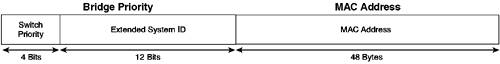
EAN: 2147483647
Pages: 135