Introduction
| The following sections are presented as an introduction:
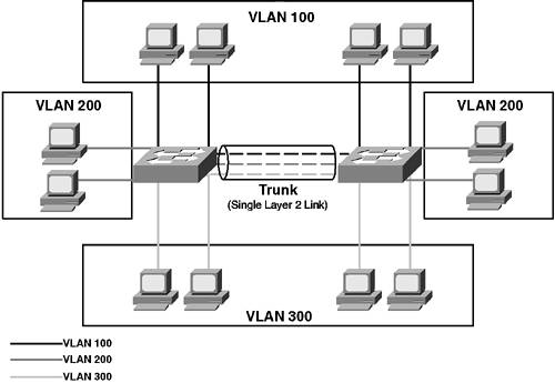
TrunkingTrunking allows switches to interconnect with each other and allows transport traffic from multiple VLANs over the same Layer 2 link. If you think about a normal access port on a switch, all traffic that enters or leaves the switch has no indication whatsoever as to the VLAN the traffic belongs to. When a frame is received on an access port, the switch internally assigns a VLAN tag to the frame based upon the VLAN configured for the access port. For example, if a frame is received on an access port that belongs to VLAN 100, internally the switch assigns a VLAN tag of 100 to the frame. This tag ensures that the switch knows which set of egress ports the frame can exitonly egress ports that belong to VLAN 100. Once the frame forwarding decision has been made by referencing the bridge table, the frame is forwarded to the appropriate egress port, at which point the internal VLAN tag is stripped, restoring the original frame, which is then transmitted out the egress port. Trunking extends this VLAN tagging concept across multiple switches. Essentially, a VLAN tag is attached to all traffic over a trunk interface, allowing the receiving switch to identify the correct VLAN that traffic belongs to. Figure 3-1 illustrates the concept of trunking. Figure 3-1. Trunking
In Figure 3-1, three VLANs exist across two switchesVLANs 100, 200, and 300. The switches are interconnected by a trunk that transports (multiplexes) traffic from each VLAN. This arrangement means that the two PCs in VLAN 100 connected to the left-hand switch can communicate directly via Layer 2 with the two PCs in VLAN connected to the right-hand switch. To multiplex the traffic across a single physical link, each switch must tag each frame with the VLAN the frame belongs to. This tag allows the receiving switch to forward the frame out the correct ports. Trunking OperationTrunking operation defines the encapsulation a trunk uses for tagging VLANs and how trunks are negotiated. Three key considerations should be discussed with regards to trunking operation:
Trunk EncapsulationsTrunk encapsulation refers to the protocol that is used to tag frames placed onto a trunk. On Ethernet networks, two trunking encapsulations are common within Cisco Catalyst switch networks:
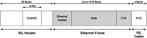
Historically, other trunking technologies, such as ATM LANE and 802.10, exist on such networks, but those technologies are outside the scope of this book. Cisco Inter-Switch Link (ISL) is proprietary and was developed before the Institute of Electrical and Electronic Engineers (IEEE) 802.1Q standards-based approach was available. By default, two Cisco Catalyst switches will negotiate an ISL trunk on auto-negotiating trunk ports (as long as each side supports ISL). Many implementations still use ISL, so understanding ISL is important for your overall knowledge of trunking. Cisco ISL prepends a 26-byte ISL header and appends a 4-byte cyclic redundancy check (CRC) checksum to the original frame. The header contains various fields, including the all-important 10-bit VLAN ID, as shown in Figure 3-2. Figure 3-2. Inter-Switch Link Encapsulation
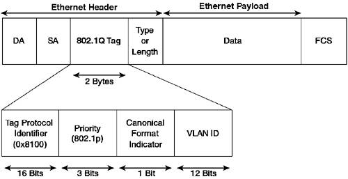
802.1Q was developed by the IEEE to allow multi-vendor support for VLANs. Another standard used within 802.1Q is 802.1p, which allows for differentiation of the priority of different Layer 2 traffic. This standard is important for providing quality of service (QoS) at a Layer 2 level. 802.1Q is similar to ISL in that it tags frames; however, where it tags the frame is different. Figure 3-3 shows the structure of an 802.1Q-tagged Ethernet frame. Figure 3-3. 802.1Q Ethernet Frame
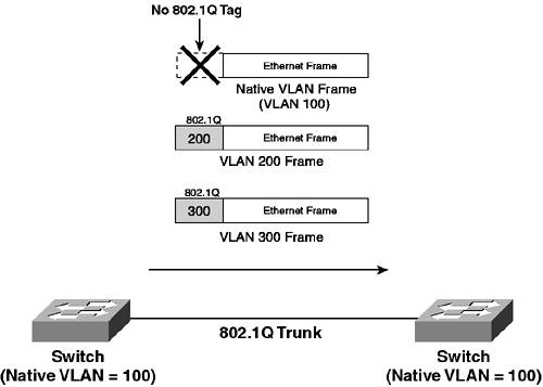
As you can see, the 802.1Q header is actually within the Ethernet frame. This arrangement is different from ISL, which encapsulates or wraps the Ethernet frame with an ISL header. Having the 802.1Q header within the frame introduces possible issues with the maximum transmission unit (MTU) for Ethernet. The IEEE 802.3ac standard specifies an extension to the Ethernet MTU to allow for larger frames. The priority field (802.1p) uses three bits to define the relative priority of the tagged traffic. This priority is designed to interoperate with the IP precedence field in IP packets (which surprisingly also uses 3 bits). TIP ISL has a User field that is used by Cisco Catalyst switches to carry priority information (identical to 802.1p) over ISL trunks. 802.1p is discussed in depth in Chapter 9, "Quality of Service." Another notable difference between 802.1Q and ISL is that 802.1Q has the concept of a native VLAN, with all traffic belonging to the native VLAN being sent without an 802.1Q tag over the trunk. The purpose of the native VLAN is to allow interoperability with non-802.1Q ports (e.g., access ports). Because traffic is not tagged on the native VLAN, if a port configured as an 802.1Q trunk receives untagged traffic (for example, from a PC connected to the trunk), the switch assumes the traffic belongs to the native VLAN and is forwarded accordingly. Figure 3-4 demonstrates the concept of native VLANs. Figure 3-4. 802.1Q Native VLAN
In Figure 3-4, the native VLAN is VLAN 100. Any VLAN 100 traffic transmitted across the trunk does not have an 802.1Q tag attached; however, all other VLAN traffic does have an 802.1Q tag attached. Because the native VLAN is not tagged, it is important that both sides of an 802.1Q trunk are configured correctly with the same native VLAN; otherwise, a switch may place native VLAN traffic into the wrong VLAN. Trunking NegotiationTrunking negotiation allows a port to auto-negotiate a trunk if the connected remote port supports trunking as well. This form of negotiation is similar in concept to EtherChannel negotiation. If both ends of a link support trunking, they can negotiate to form a trunk that transports traffic from multiple VLANs, rather than just a single VLAN. Trunking uses a protocol called Dynamic Trunking Protocol (DTP) to facilitate the negotiation of trunks. Negotiation consists of sending DTP frames that specify various parameters to influence the negotiation process. DTP allows for the negotiation of the following:
By default, ISL encapsulation is preferred over 802.1Q, but encapsulation is dependent on the port capabilities of each end of the link, which are transmitted via DTP. You can hard code the encapsulation you wish to use and still allow DTP to negotiate whether a trunk comes up or not. NOTE DTP is derived from Dynamic Inter-Switch Link protocol, also known as DISL. DISL was developed by Cisco to specifically negotiate ISL-based trunks. DTP was then developed to include support for other trunk encapsulations, namely 802.1Q. The trunk mode of a port determines whether or not it tries to negotiate a trunk using DTP. A port can be configured to five different modes:
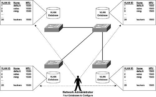
As you can see from the preceding list, various modes exist that determine how a port negotiates (or doesn't negotiate) to become a trunk port (or non-trunk port). You learn about the compatible DTP modes in Scenario 3-2. Allowed VLANsBy default, a trunk configured between two Cisco switches trunks traffic for all VLANs between the two switches. For example, if you have 100 active VLANs on each switch, when you set up a trunk, traffic from all 100 VLANs is trunked across the trunk. In some scenarios, this configuration may be undesirable because a switch might have devices connected to only a specific few VLANs. Cisco Catalyst switches allow you to configure a trunk to transport traffic from only a specific list of VLANs (called the allowed VLAN list). VLAN Trunking ProtocolVLAN Trunking Protocol (VTP) is essentially a Cisco proprietary VLAN management tool that is designed to propagate VLAN information across a distributed switching environment that is interconnected via trunks. As you learned in Chapter 2, "VLAN Operations," VTP requires configuration before VLANs can be configured even on a single switch. NOTE A standards-based VLAN management protocol exists called Generic VLAN Registration Protocol (GVRP); it is an application of the Genetic Attribute Registration Protocol (GARP). GARP and GVRP are described in the IEEE 802.1p specification. Figure 3-5 shows a scenario where four switches are interconnected via trunks in a distributed switching environment. Figure 3-5. Sample Distributed Switch Network
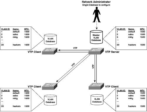
In Figure 3-5, 20 VLANs exist throughout the network, with devices existing in each VLAN located on any one of the four switches. You can see that 20 separate VLAN databases exist on each switch that define each VLAN, storing information such as VLAN ID, VLAN name, MTU, and more for each. If a network administrator had to manually define each database in this network and if a new VLAN were added or a change to an existing VLAN were made (e.g., changing a VLAN name), then the network administrator would need to configure the changes on each switch in the network (i.e., twenty times). Obviously, in large networks with many switches, this process becomes administratively prohibitive and prone to error. VTP allows for the automatic propagation and distribution of VLAN database information throughout a Layer 2 network. VTP does not propagate port-based VLAN information (such as the ports belonging to each VLAN); it merely propagates information about each VLAN that exists in the network and the various administrative parameters (such as VLAN ID, name, MTU, and so on) associated with VLAN. Figure 3-6 shows the network of Figure 3-5 with a centralized VLAN database that is propagated to all other databases. Figure 3-6. Sample Distributed Switch Network with VTP
In Figure 3-6, a VTP server is defined that holds a master copy of the VLAN database. The VTP server has read-write access to the VLAN database, meaning administrators can configure the VLAN database only from the VTP server. The VTP server then distributes a copy of VLAN database to all the other switches, which are configured as VTP clients. A VTP client has only read access to the VLAN database, which ensures the VLAN database is kept in synchronization because only the VTP server can actually modify the VLAN database. As you can see in Figure 3-6, the VLAN database is configured centrally from a single point, and VTP distributes the VLAN information to the rest of the network. VTP OperationVTP is a client/server protocol that enables the propagation of VLAN information within an administrative collection of switches known as the VTP domain. Each switch can act as a VTP client or server, which determines if they have read-only or read-write access to the VLAN database. All VTP devices transmit VTP advertisements, which contain VLAN database information. The following components of VTP operation are now discussed:
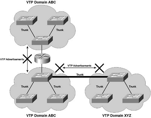
VTP DomainA VTP domain defines a collection (or administrative boundary) of VTP devices that share the same VLAN database information. A VTP domain is a Layer 2 entity, meaning that a VTP domain can encompass only a Layer 2 network. Being a Layer 2 entity also means that Layer 3 devices, such as routers, terminate VTP domains. The VTP domain is communicated in all VTP messages, which means that all devices within the same VTP domain must be configured with an identical VTP domain name. If a VTP message is received that includes a different VTP domain name from the local domain name, the VTP message is ignored. A Cisco Catalyst switch can belong only to a single VTP domain. Figure 3-7 demonstrates the concept of VTP domains. Figure 3-7. VTP Domains
In Figure 3-7, VTP advertisements sent between domain ABC and XYZ are rejected at the opposite domain because the VTP domain names are different and a switch can belong only to a single VTP domain. Notice also that the VTP domain ABC has been split into two due to the router that sits between each Layer 2 network. Although these VTP domains have the same name, they operate as separate entities because VTP messages cannot traverse the router. VTP ModesVTP is a client/server protocol that allows a VTP server read-write access to the VLAN database and allows a VTP client read-only access to the VLAN database. A Cisco Catalyst switch possesses the capability to act as a VTP server or client. The role that each switch plays in the VTP network is referred to as the VTP mode. The server mode is the default mode on Cisco Catalyst switches, ensuring that out of the box you can create VLANs (after setting a VTP domain name). The VTP client/server architecture means you can configure a centralized VTP server switch from which you make any VLAN adds/moves or changes and all modifications to the VLAN database are propagated to each VTP client switch. TIP It is always good practice to enable at least two VTP servers in your network for redundancy purposes. A VTP server should be at or near the center of your LAN and should be the highest-performance switch available. VTP also has another mode called transparent, in which the switch ignores any VTP messages but propagates the messages to ensure any VTP servers/clients connected to the switch receive VTP information. TIP A switch operating in VTP transparent mode and running VTP version 1 will not propagate any VTP messages that do not have the same VTP domain name as the locally configured VTP domain name. In VTP version 2, a VTP transparent switch propagates VTP messages, regardless of the VTP domain listed in each. The final mode available is off, in which the VTP message is ignored and is not propagated to other switches. The VTP mode of off is available only on CatOS-based switches. VTP AdvertisementsVTP advertisements are the messages that are sent between VTP devices within a VTP domain. VTP advertisements are used to propagate VLAN database information. Each advertisement contains the following fields:
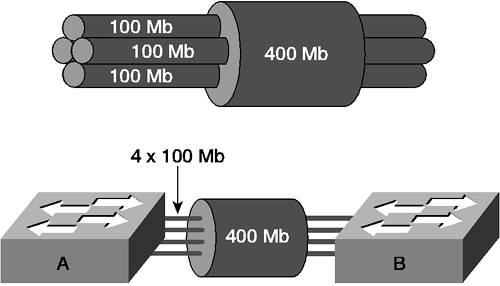
VTP advertisements are sent periodically (every 30 seconds) or whenever a VLAN configuration change is made. VTP advertisements are multicast via Ethernet SNAP frames, using a multicast address of 01-00-0c-cc-cc-cc and a SNAP protocol type of 0x2003. Using multicast ensures that VTP advertisements are propagated across other network devices (such as hubs); they may be located between switches. VTP advertisements are only ever sent on trunk ports and are always sent on VLAN 1 (hence, one reason why VLAN 1 cannot be deleted). Advanced VTP FeaturesVTP offers some advanced features, which includes the ability to authenticate VTP advertisements, allowing receiving switches to verify an advertisement is authentic. This verification is achieved via the use of a VTP password that is used to sign each VTP advertisement. VTP also allows for the pruning of trunks, which is the automatic clearing of unnecessary VLANs from trunks. VTP SecurityVTP provides a VTP password option that allows all messages to be signed with a message digest (MD5) hash. A hash is a one-way function that combines the contents of the message with the VTP password to create a unique hash value of fixed length, which is then appended to the VTP message. The VTP message cannot be derived from the hash because the hashing algorithm is one way. When a VTP device receives the message (with a hash attached), it runs the message through the same MD5 algorithm with the locally configured password. If the locally computed hash value matches the received hash value (this only happens if the passwords are identical on the sending device and receiving device), then the message is authentic. VTP PruningVTP pruning is a feature that allows trunks to be pruned automatically of VLAN traffic. If you enable trunking and do not manually clear any VLANs from the trunk, traffic from all VLANs is propagated across the trunk. If a switch does not connect to any devices within a particular VLAN, the switch does not need to receive traffic for that VLAN. VTP pruning enables each switch to dynamically signal (via VTP Join messages) to a remote switch if it needs to receive traffic for each VLAN in the database. This process allows trunks to dynamically prune unnecessary VLAN traffic. Bandwidth AggregationBandwidth aggregation is used to provide the aggregation of multiple physical links, creating a single virtual link that carries the bandwidth sum (or close to the sum) of each physical link. Bandwidth aggregation is used to provide both performance and redundancy. Figure 3-8 illustrates the basic concept of bandwidth aggregation, as it applies to LANs. Figure 3-8. Bandwidth Aggregation on a LAN
In Figure 3-8, four physical 100 Mbps full-duplex interfaces are aggregated to create a single virtual 400 Mbps full-duplex (800 Mbps bandwidth in total) interface, which boosts performance between the two switches. The aggregated interface is represented as a single Layer 2 link to each switch, which means spanning tree (discussed in Chapter 4, "Spanning Tree") sees only a single interface as opposed to four separate interfaces. If a physical interface fails, the virtual interface stays up (it just has one less physical interface, so obviously offers a lesser amount of performance), which means the spanning tree doesn't see the failure and does not react to the failure, preventing disruption to the Layer 2 network. In short, bandwidth aggregation provides physical layer redundancy that is transparent to higher layers, removing the requirement for protocols such as spanning tree to deal with redundant links. Cisco was the first switch vendor to introduce a bandwidth aggregation protocol called EtherChannel for LAN switches, and EtherChannel is still popular today. Although EtherChannel is proprietary, the demand for the feature is such that many third-party network card vendors offer support for the protocol. NOTE Recently, a standards-based bandwidth aggregation specification was released by the IEEE; it is known as the IEEE 802.1ad standard. Much of how this protocol works is derived from EtherChannel. EtherChannel OperationEtherChannel aggregates up to eight physical Ethernet links into a single virtual Layer 2 link (also known as an EtherChannel bundle), identical to the topology shown in Figure 3-1. The goals of EtherChannel are to provide the following:
EtherChannel enhances performance by transmitting frames over multiple physical links. EtherChannel provides redundancy in the event of a physical link failure, because other physical links are still up to transport frames. High availability is achieved by EtherChannel's fast recovery times in the event of a failure, ensuring the impact to the network is zero or minimal at worst. EtherChannel PerformanceIf you consider Figure 3-8, you can see that four physical links exist over which to transport a frame. By load sharing over each of these links, performance of up to the combined speed of the links is possible. To achieve the performance results possible by aggregating multiple physical links, EtherChannel supports the use of one or more of the following mechanisms to load share traffic over the bundle:
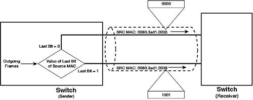
The first and simplest implementation of EtherChannel loads shares based on the source or destination MAC address (Layer 2 address) of the frame being transmitted. Figure 3-9 illustrates this process. Figure 3-9. Load Sharing Using MAC Addresses
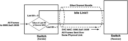
In Figure 3-9, load sharing based upon source MAC address is enabled. The source MAC address of each frame is examined, and the last bit of the MAC address is used to determine which physical link the frame should be transmitted over. If four links existed in the bundle, the last two bits of the MAC address are used, because this provides four possible values (one for each link). The scenario described in Figure 3-9 has a major issue. Because the load sharing is based upon the source MAC address, if a large number of frames originates from the same source MAC address, all of those frames are sent across the same link. Figure 3-10 illustrates this problem. Figure 3-10. Limitations of MAC-based Load Sharing
You could overcome the issue in Figure 3-10 by using destination MAC addresses to load share. However, this scenario also becomes a problem if the scenario in Figure 3-10 is reversed, where a large number of frames are sent to the same destination MAC address. TIP You don't have to configure the same method of load sharing at each end of an EtherChannel bundle. It is common to use source-based forwarding on a switch (connected to a router) and then use destination-based forwarding on the router. Because all communication to the router is performed using the same destination MAC address, source-based forwarding on the switch is configured to prevent frames from traversing only a single physical link in the bundle. Some implementations also support load sharing based upon Layer 3 (IP addresses) and Layer 4 parameters (TCP/UDP ports), using similar principles to those shown in Figure 3-10 and just replacing Layer 2 addressing with Layer 3 addressing and/or Layer 4 parameters. Some Cisco Catalyst switches can combine source and destination addresses by performing an Exclusive OR (XOR) operation to both the source and destination addresses. At its simplest, this combining involves performing an XOR of the low-order bits of the source and destination addresses. In more recent Catalyst switches, the source and destination addresses are hashed to produce a much more random output than the low-order bits of a network address, with each hash then being XORed. EtherChannel Redundancy and High AvailabilityIf a link fails in an EtherChannel bundle, traffic that would normally be sent over the failed link is automatically redirected over the remaining active links. This failure is transparent to the network and is performed automatically by the switch. Obviously, the performance of the bundle is degraded while the failed link is down, and it is important to be able to detect and respond quickly to the failure. Cisco Catalyst switches can send a Simple Network Management Protocol (SNMP) trap or SYSLOG trap upon a link failure to notify network operations staff of the failure. EtherChannel Negotiation (PAgP)Port Aggregation Protocol (PAgP) enables EtherChannel bundles to be dynamically created between two devices, depending on the capabilities of each device's ports. When a port configured in an EtherChannel bundle comes up, the PAgP mode determines whether or not the port forms a bundle and whether or not it attempts to negotiate a bundle by sending PAgP frames. PAgP peers exchange information that identifies each other (which ensures that ports in a configured EtherChannel bundle that are connected to separate devices do not form a bundle) and information that indicates which ports specifically should bundle (which ensures that the correct ports form a bundle). PAgP peers also exchange information about features that cause known issues with EtherChannel, which then stops the bundle from forming. NOTE PAgP frames are exchanged via SNAP Ethernet multicast frames with a destination address of 01-00-0c-cc-cc-cc and a SNAP protocol type of 0x0104. PAgP frames are always sent on VLAN 1 over trunk interfaces. EtherChannel bundles can operate in one of the following PAgP modes:
The sending of PAgP frames is disabled when you use the on or off modes, while PAgP frames are exchanged when you use the auto or desirable modes. Make sure you understand which PAgP modes are compatible with each other, so that an EtherChannel bundle will form. This topic is discussed in detail in Scenario 3-4. NOTE The IEEE 802.1ad specification describes a bandwidth aggregation technique for LAN interfaces that is very similar to Cisco EtherChannel aggregation. Instead of using PAgP, link aggregation control protocol (LACP) is used to negotiate bundles. LACP defines four modes of operation, very similar to PAgP. At the time of this writing, support for LACP is offered only in the Catalyst 4000 and 6000 switches, beginning with the CatOS 7.1(1) release. |
EAN: 2147483647
Pages: 135