3.3 Bounds on Performance
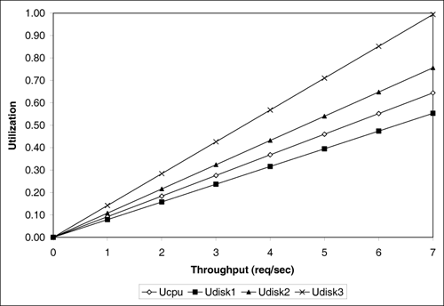
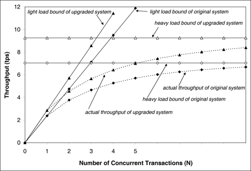
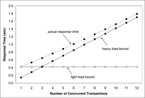
| Upper bounds on throughput and lower bounds on response time can be obtained by considering the service demands only (i.e., without solving any underlying model). This type of bounding analysis can be quite useful since it provides the analyst with the best possible performance one could hope from a system. The bounding behavior of a computer system is determined by its bottleneck resource. The bottleneck of a system is that resource with the highest utilization (or, equivalently, the resource with the largest service demand). Example 3.9.Consider again the database server of Example 3.2 and the service demands for the CPU and the three disks computed in Example 3.4. The service demands were computed to be: DCPU = 0.092 sec, Ddisk1 = 0.079 sec, Ddisk2 = 0.108 sec, and Ddisk3 = 0.142 sec. Correspondingly, the utilization of these devices are 35%, 30%, 41%, and 54%, respectively (from Example 3.4 and Table 1.1). What is the maximum throughput Using the Service Demand Law, it follows that UCPU = DCPU x X0 = 0.092 x X0, Udisk1 = Ddisk1 x X0 = 0.079 x X0, Udisk2 = Ddisk2 x X0 = 0.108 x X0, and Udisk3 = Ddisk3 x X0 = 0.142 x X0. Since the service demands are constant (i.e., load-independent), they do not vary with the number of concurrent transactions in execution. The service demands do not include any queuing time, only the total service required by a transaction at the device. Therefore, as the load (i.e., as the throughput, X0) increases on the database server, each of the device utilizations also increases linearly as a function of their individual Di's. See Fig. 3.6. As indicated in the figure, the utilization of disk 3 will reach 100% before any other resource, because the utilization of this disk is always greater than that of other resources. That is, disk3 is the system's bottleneck. When the system load increases to a point where disk 3's utilization reaches 100%, the throughput cannot be increased any further. Since X0 = Udisk3/Ddisk3, X0 Figure 3.6. Utilization vs. throughput for Example 3.9. This example demonstrates that Equation 3.3.17 The resource with the largest service demand will have the highest utilization and is, therefore, the system's bottleneck. This bottleneck device yields the lowest (upper bound) value for the ratio 1/Di. Therefore, Equation 3.3.18 This relationship is known as the upper asymptotic bound on throughput under heavy load conditions [3]. Now consider Little's Law applied to the same database server and let N be the number of concurrent transactions in execution. Via Little's Law, N = R x X0. But, for a system with K resources, the response time R is at least equal to the sum of service demands, Equation 3.3.19 which can be rewritten as Equation 3.3.20 This relationship is known as the upper asymptotic bound on throughput under light load conditions [3]. Combining Eqs. (3.3.18) and (3.3.20), the upper asymptotic bounds are: Equation 3.3.21 To illustrate these bounds, consider the same database server in Examples 3.2 and 3.4. Consider the two lines (i.e., from Eq. (3.3.21)) that bound its throughput as shown in Fig. 3.7. The line that corresponds to the light load bound is the line N / 0.421 (solid line with solid diamonds). The horizontal line at 7.04 tps (solid line with unfilled diamonds) is the heavy load bound for this case. The actual throughput curve is shown in Fig. 3.7 as the dotted line with solid diamonds and lies below the two bounding lines. Consider now that the bottleneck resource, disk 3, is upgraded in such a way that its service demand is halved (i.e., by replacing it with a new disk that is twice as fast). Then, the sum of the service demands becomes 0.35 (= 0.092 + 0.079 + 0.108 + 0.071) sec. The maximum service demand is now that of disk 2, the new bottleneck, and the new heavy load bound (i.e., the inverse of the maximum service demand) is now 9.26 (= 1/0.108) tps. The solid lines with triangles show the bounds on throughput for the upgraded system. The actual throughput line (dashed line with triangles) is also shown. Figure 3.7. Bounds on throughput example. Note that when the bottleneck resource was upgraded by a factor of two, the maximum throughput improved only by 32% (from 7.04 tps to 9.26 tps). This occurred because the upgrade to disk 3 was excessive. Disk 2 became the new bottleneck. It would have been sufficient to upgrade disk 3 by a factor of 1.32 (= 0.142/0.108) instead of 2 to make its service demand equal to that of disk 2. By using simple bottleneck analysis and performance bounds in this manner, performance can be improved for the least amount of cost. Example 3.10.Consider the same database server of Examples 3.2 and 3.4. Let the service demand at the CPU be fixed at 0.092 sec. What should be the values of the service demands of the three disks to obtain the maximum possible throughput, while maintaining constant the sum of the service demands at the three disks? Note that this is a load balancing problem (i.e., the goal is to maximize the throughput by simply shifting the load among the three disks). As demonstrated, the maximum service demand determines the maximum throughput. In this example, since the CPU is not the bottleneck, the maximum throughput is obtained when the service demands on all three disks is the same and equal to the average of the three original values. This is the balanced disk solution. In other words, the optimal solution occurs when Ddisk1 = Ddisk2 = Ddisk3 = (0.079 + 0.108 + 0.142)/3 = 0.1097 sec. In this case, the maximum throughput is 9.12 (= 1/0.1097) tps. Therefore, the maximum throughput can be expanded to increase 29.5% (i.e., from 7.04 tps to 9.12 tps) simply by balancing the load on the three existing disks. To be convinced that the balanced disk solution is the optimal solution, assume that all disks have a service demand equal to D seconds. Now, increase the service demand of one of them by Now consider a lower bound on the response time. According to Little's Law, the response time R is related to the throughput as R = N/X0. By replacing X0 by its upper bound given in Eq. (3.3.21), the following lower bounds for the response time can be obtained. Equation 3.3.22 Example 3.11.Consider the same database server as before. What is the lower bound on response time? The sum of the service demands is 0.421 (= 0.092+0.079+0.108+0.142) and the maximum service demand is 0.142 sec. Therefore, the response time bounds are given by
Equation 3.3.23 These bounds are illustrated in Fig. 3.8, which also shows the actual response time curve. As seen, as the load on the system increases, the actual response time approaches the heavy load response time bound quickly. The actual values of the response time are obtained by solving a closed QN model (see Chapter 12) with the help of the enclosed ClosedQN.XLS MS Excel workbook. Figure 3.8. Bounds on response time example. |
EAN: 2147483647
Pages: 166
 1/
1/


 seconds, for
  > 0. Since the sum of the service demands is to be kept constant, the service demand of at least one other disk has to be reduced in such a way that the sum remains the same. The disk that had its service demand increased will now have the largest service demand and becomes the bottleneck. The new maximum throughput would be 1/(
