2.2 Modeling a Single Domain
| After gathering and understanding requirements for a domain, we select or invent the appropriate abstractions and make detailed decisions about how the domain works. (This abstraction step is often overlooked, but it is critical to success.) The result is an executable UML model that defines the behavioral requirements for a domain in excruciating detail.
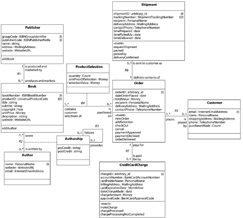
To find domain abstractions and describe each domain precisely, the developer must understand the domain's mission and have sufficient detailed information to make decisions about the exact behavior of the domain. The executable UML model for each domain (or subsystem in a domain) comprises a set of tightly connected class, state, and action models. 2.2.1 ClassesOn the first iteration, we have a domain chart that outlines each domain and a set of use cases for each domain. Next, we are ready to begin modeling each of the domains. A domain is full of real and hypothetical things. We abstract like things and call them classes. In forming such abstractions, we choose to ignore most of the things. Those remaining are grouped according to perceptions about what it means to be "like." Our ideas of what constitute appropriate criteria for establishing likeness depend on the purpose we have in mind in other words, on the purpose or mission of the domain. We choose attributes that support the ideas of likeness we have in mind when we abstract the class. Relationships exist between the things in the domain, and we abstract them as associations between classes. The result of the abstraction process is a class diagram (Figure 2.2) comprising classes, attributes and associations, and descriptions for each element. Figure 2.2. Class Diagram
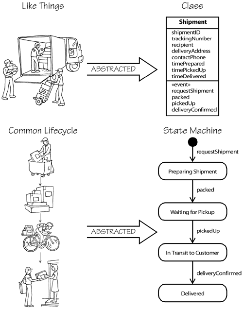
2.2.2 State MachinesMany things go through various stages in their lifetimes. The collection of stages is called a lifecycle. A state machine formalizes a lifecycle in terms of states, events, transitions, and procedures with their actions. At any given time an abstraction representing some aspect of a thing is in exactly one stage of its lifecycle. Hence, a Person abstraction may be At Work while the same person, acting as an Employee abstraction, is In Meeting. Like things have a common lifecycle, so when a group of like things is abstracted as a class, the common lifecycle is abstracted as the object's state machine. This correspondence is illustrated in Figure 2.3. Figure 2.3. One State Machine for Each Class
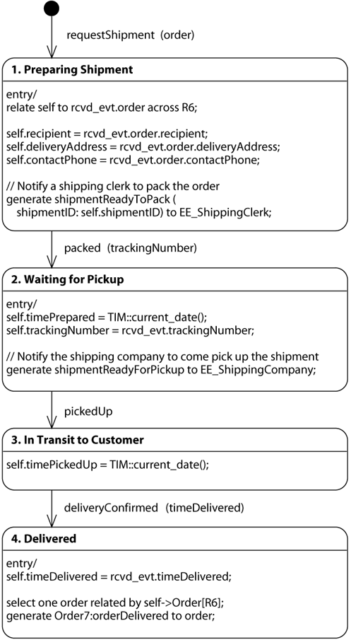
The state machine is represented using a subset of the statechart diagram, as shown in Figure 2.4. This subset is chosen to be rich enough to model the lifecycles of the abstractions, in contrast to the more complex statechart diagrams required for modeling software structure. The subset is also chosen to be sparse enough to ease model compilation: A complex language requires more complex model compilers. Figure 2.4. Statechart Diagram for Shipment Class Showing Executable Actions
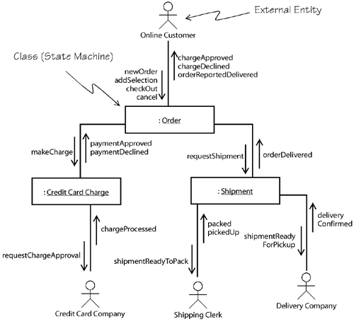
To ensure completeness, a state machine can also be rendered as a state transition table that has one cell for each state and event. Checking whether there is a transition for each cell is often beneficial, revealing missing transitions and behaviors. Objects communicate by sending signals back and forth. A collaboration diagram, such as the one in Figure 2.5, shows the communicating signals between objects. Figure 2.5. Collaboration Diagram
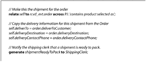
2.2.3 ProceduresEach state on the statechart diagram has an associated procedure that takes as input the data items associated with the event that triggered entry into the state. Each procedure comprises a set of actions, and each action carries out some functional computation, data access, signal generation and the like. Actions are like code, except at a higher level of abstraction, making no assumptions about software structure or implementation. UML has a definition of the semantics of actions, but it does not yet have a notation for action models. In Figure 2.6 and throughout the book, we use an existing, action semantics compliant language [2] for actions. Figure 2.6. Procedure for State Creating Shipment Consisting of a Series of Actions
2.2.4 Iterating the Domain ModelsTypically, the very first time one builds a domain model, building the class model is an easy, short-lived task, but that simple class model makes the state-modeling activity almost impossible: The state machines are too large and very complicated. The problem is incomplete factoring of the classes. Often a first-time class diagram has only classes that model tangible things, but no classes for desired behavior. Instead, the behavior is allocated to the tangible things, which, of course, makes them extremely complex. The solution is to refactor the classes so that each class is simpler, abstracting just one role as a class, instead of the many roles taken on by a single thing. Then the state machines for the classes become significantly easier to build. The class diagram and the statechart diagrams are tightly connected, but with practice, the work can be carried out without too much iteration between the two kinds of model. We often find that the action-modeling step is key to finding missing attributes sometimes entire missing classes and associations. It also helps locate navigational and hidden constraints that have been incorrectly or incompletely specified. 2.2.5 Iterating between System and Domain ModelingAbstracting classes in the domain requires some distance from the previous steps in the process because use cases can easily lead to poor abstractions. For example, use cases that outline a set of reports to be produced can easily yield classes that produce each report instead of a report generator based on a set of configurable fields. Similarly, requirements for producing time sheet reports for a small consulting firm could lead to a lot of special-purpose code, when a spreadsheet would be faster, more economical, and far easier to maintain. These examples, and many like them, share several common properties. First, the abstraction required is one layer of abstraction removed from the original requirements. Instead of the model capturing the details of each specific report, the model captures field, type, and heading in the first example. Similarly, for the second example, the correct abstractions are cell, formula, and cell format, not consultant, client, project, or hours. Second, the details of the specific application are expressed in data, while the logic for the abstractions remains constant. In the time sheet example, the model has classes cell, formula, and cell format, while the instances of cells can contain the name of the project, the name of the consultant, the number of hours worked, and the formula that produces the bills. Third, because the application is expressed in data as instances of the more abstracted classes (project name as an instance of cell, for example) the model is highly reusable in other contexts. We simply replace the instances with data describing the new application. For these reasons, you must be willing to go back and refine, even completely reconstruct, the domain chart as you build the domain models. |
EAN: 2147483647
Pages: 161

