IEEE 802.11 WLAN Components
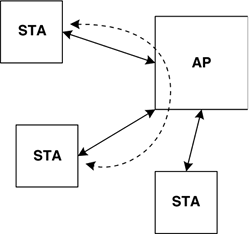
| Before continuing with the discussion of the Access control methods and the Address fields in the IEEE 802.11 header, we will first briefly cover the terminology associated with the "intermediate nodes" (APs) in IEEE 802.11 WLANs. It is impossible to understand the reason for there being four Address fields in the IEEE 802.11 MPDU header unless one understands the nature and use of the AP. Strictly speaking, an AP only serves to mediate communications between wireless stations in its vicinity, in particular those stations with which it has formed an "association." Figure 6-7a illustrates the AP function, which facilitates wireless communication between various STAs with which it has associated. Figure 6-7a. Wireless LAN components wireless only
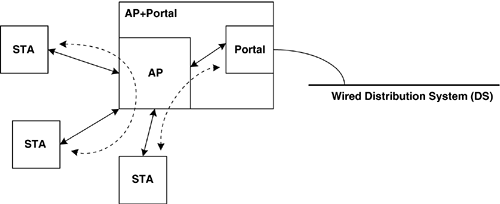
Devices called "APs" frequently also have integrated "Portal" functionality, which is specifically a gateway to a non-IEEE-802.11 wired LAN, so that a combined "AP + Portal" device effectively acts as a bridge between the wireless and wired domains. Devices that are commonly known as APs typically include a connection to the wired "Distribution System," so that the STAs in its local BSS can access devices outside their immediate vicinity. The wired DS may link one BSS to a wired backbone, or link more than one BSS to other nearby BSSs such that they all form an ESS. An ESS is a collection of BSSs that appears to be one large BSS, as far as the LLC sub-layer is concerned. The DS that interconnects the BSSs may be any convenient medium, and is frequently wired (Ethernet, or IEEE 802.3). There is also the possibility to use the WM itself as a distribution system for the ESS, but that is not part of the IEEE 802.11-1999 standard. Figure 6-7b illustrates a scenario that comprises a wired component[9] in which one STA is communicating through the Portal, while two other wireless STAs are exchanging data through the AP at the same time.
Figure 6-7b. Wireless LAN components wireless with wired
Beyond the expected "usual case" that one AP will be in between any two communicating wireless STAs, there is the additional possibility that multiple APs may be needed to facilitate communication between two stations. This is why the IEEE 802.11 header needs enough space for up to four MAC addresses…the additional addresses in data frames represent an intermediate transmitter's address and an intermediate receiver's address. The most common scenario for WLAN data traffic is probably a situation in which the two communicating stations are clients of the same AP, in which case only three Address fields would be present in the MPDU header. This case is illustrated in Figure 6-7a. Another very common scenario, shown in Figure 6-7b, would be that the wireless STA is communicating through a single AP to a station reachable via the wired LAN on the other side of the AP. In either case, only a single AP is involved in the data exchange. Because this situation may be logically equivalent to a single AP (e.g., if the APs and their common DS form a single broadcast domain), the format of the MPDUs on the WM is likely to require only three Address fields. The case in which a frame must traverse multiple APs to reach a given station is not necessarily common, although it uses the two additional Address fields in a slightly different way compared to the two-stations-communicating through a common AP scenario. The meaning of the two additional Address fields is a slight generalization of the MAC-SA and MAC-DA concepts. Other settings of the ToDS and FromDS bits involve defining one of the Address fields to hold a value known as the Basic Service Set (BSS) Identification[10] (BSSID), which is a unique number that, obviously, is used to identify a given BSS within an ESS. In an infrastructure BSS, the AP defines the BSSID to be the MAC address of the STA within the AP. In contrast, when a WLAN is operating as an independent BSS (IBSS), the first station in the IBSS defines the BSSID. The STA chooses a 46-bit random[11] number and concatenates those 46 bits with two additional bits to create a 48-bit locally administered MAC address (i.e., a MAC address that is not globally unique). This is accomplished by setting the least-significant two bits of the BSSID to "10" (where the least significant bit is "0"). Rather than confuse this definition by discussing bit ordering issues, simply note that the least-significant octet of the BSSID in the IBSS case can never be an odd number (i.e., it will be divisible by two because the least-significant bit is "0").
One of the other controlling factors in the selection of the values in the "ToDS" and "FromDS" bits is that certain combinations are only allowable for certain levels of association. For example, if a STA has not been associated or authenticated, it may not set either of these bits. In addition, certain management frames are sent with these bits clear, such as Beacons (sent by the AP). Once a STA has been fully associated and authenticated, it can set the ToDS bit. Only APs should be setting the FromDS bit. Frame Handling MulticastBecause of hidden nodes, multicast[12] frames are not transmitted directly onto the WM by any STA (unless it is in IBSS mode, which has no hidden nodes by assumption). Multicasts must be sent by the AP, since that is the only way for all the STAs in the BSS to hear them. However, if the STA sent the multicast frame as a multicast, then all the STAs in range of its radio would hear the frame. However, the AP would then re-issue the frame into the BSS so that the other STAs could hear it, and that would result in the STAs within range of the STA that sent the frame in the first place getting a second copy of the multicast frame.
The way around this is that the STA sends the frame with the ToDS bit set to "1" and the Address-1 field set to the BSSID, the MAC address of the STA in the AP. The frame's ultimate MAC Destination Address (in the Address-3 field) is the desired multicast address. The AP understands this frame format and sends a new frame out as a native multicast, with the FromDS bit set to "1". In this case, the Address-2 field still contains the BSSID, since that allows a STA that can hear multiple APs to filter only the multicasts that are from the AP with which it has associated.[13]
|
EAN: 2147483647
Pages: 60

