The Mother of All Networking Standards
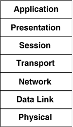
| The old ironic aphorism that the great thing about standards is that there are so many to choose from is funny because it is so true. The profusion of data networking standards partially derives from the many different organizations that create such standards, such as ANSI, CCITT, IEEE, IETF, ITU-T, and so forth, and partially from the many different layers at which standards may be defined. Private companies also espouse their own protocols, and frequently "embrace and extend" openly created protocols for their own purposes. The main system of classifying data networking standards is the OSI-RM, which illustrates an idealized protocol stack that supports functionality distributed throughout seven interdependent layers. During the Open Systems Interconnection (OSI) networking protocol suite standardization effort, which started in the mid-1970s and continued through the late 1980s and early 1990s, a form of division of labor was employed such that a different WG designed each protocol layer, in such a way that the details of the internal operation of any given protocol layer were irrelevant, as long as each layer provided a certain set of well-defined services to the layer above it. Each layer likewise depended on a different set of well-defined services that would be exposed by the layer below it. In the early days of the standardization of the protocols that would eventually comprise the seven layers of the OSI Reference Model (OSI-RM), the lower layers were understood best, and thus their standardization was completed first. These well-understood layers consisted of the Physical[4] and Data Link layers (some Network layer protocols were already understood as well, such as the connection-oriented Network layer of CCITT X.25). Figure 2-1 shows the complete seven-layer protocol stack defined by the OSI-RM.
Figure 2-1. OSI Reference Model
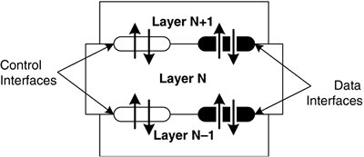
In most cases, a layer has well-defined interfaces that are used to either accept data from higher layers, or to indicate the presence of data to a higher layer. Typically, there are also control interfaces between the layers that allow a higher layer to configure a lower layer according to administrative preferences, operating conditions, and so forth. The internal operation of a layer is invisible to the layers above or below it; the important thing is that the layer must operate according to its configuration and support the functionality that is expected of it. Figure 2-2 illustrates the relationships between a given layer and the ones above and below it. Figure 2-2. Layered protocol model
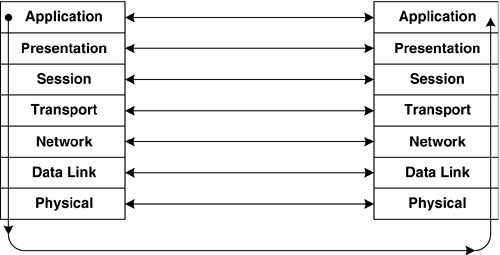
The "transmit" direction is down the stack, and the "receive" direction is up the stack. Each layer is communicating with a peer process at the same layer on another machine, using the services provided by the layers below it in the stack. Logically, the interaction is as if the peers were communicating directly, a fiction that is achieved through the presence of the lower layers. Figure 2-3 shows the logical (horizontal) and physical (vertical) operation of the layered protocol model. Figure 2-3. Operation of the layered protocol model
To understand the function of the Data Link layer, of which the MAC sub-layer is a part, and which is the layer occupied by IEEE 802.11, we must examine the context in which the Data Link layer is located. The Data Link layer is also referred to as "layer 2" of the OSI-RM, which is an abstract representation of a protocol stack that divides the job of sending and receiving data over a network into layers, each with its own well-defined function(s). The choice of seven layers was somewhat arbitrary, and had as much to do with politics than technology.[5]
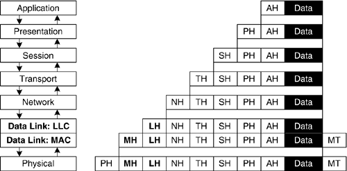
The OSI-RM's seven abstract layers each perform a specific function. Layers 2 through 6 (the middle layers) have a common characteristic, in that they perform a service (or set of services) for the layer above, and expect a service (or set of services) from the layer below. In other words, they are simultaneously "clients" of the layer below, while they offer "services" to the layer above. The reason that layer 1 and layer 7 are different is that they have no layer below or no layer above, respectively. Therefore, layer 1 only provides service(s) to layer 2 because layer 1 is at the bottom of the protocol stack, and there is no lower layer; similarly, due to its position at the top of the protocol stack, layer 7 only uses services offered by layer 6. The protocol stack manifests itself in a nested series of headers that are prefixed to data that is passed down from the layer above, as illustrated in Figure 2-4. In the ideal case, the extra header added by each layer is treated as if it were data by the layer(s) below. In practice, it is occasionally more efficient to peek into the next higher-layer protocol's header to make more accurate forwarding decisions, but that is an implementation choice and doesn't change the basic model described here, in which each layer adds its own header. Figure 2-4. Layered headers in the OSI-RM
Each layer's headers either implicitly indicate the identity of the next higher layer protocol (as in the way that IEEE 802.2 LLC is expected to follow the IEEE 802.11 MPDU header), or a layer's header will contain an explicit pointer to the proper higher-layer protocol entity, if it is possible to have more than one such higher-layer protocol. Note that the MAC layer also adds a trailer, containing a frame check sequence. The non-MAC-layer protocols simply add a header, and each protocol layer is equivalent, logically, to one of the set of headers pre-pended to the data being transferred between the two peer entities. Functions of the OSI-RM's LayersThe Physical LayerThe very bottom of the protocol stack is occupied by the Physical layer, which deals with the details of transmitting bits onto a wired or wireless physical medium, using electrical, optical, radio frequency, and other signals. Early Physical layer protocols tended to be oriented toward wired point-to-point serial communications links, since broadcast-capable LANs had not yet been invented when the initial work on the OSI protocol suite was begun. The Physical layer defines what constitutes a bit (or a symbol that represents a well-defined set of some number of bits). A bit stream may be represented by any of the following physical phenomena:
Finally, a Physical layer typically operates at a given fixed speed (once the station has attached to the medium and discovered that speed), and the bit encodings are typically defined such that the receiver may easily synchronize itself to the sender's Physical layer clock, so that the receiver can interpret each bit at the proper time, which helps the receiver avoid misinterpreting the data. To summarize the features of the Physical layer, we have seen that the Physical layer is responsible for tasks that directly relate to sending and receiving bits over the medium. The Physical layer defines the encoding of bits on the medium, may control the establishment and tear-down of connections, and can perform monitoring of the medium, such as when a modem bases its modulation on the measured characteristics of a connection, to find the best speed for the evolving conditions on the call. The bit encoding on a Physical medium may include support for Forward Error Correction (if the medium is expected to be noisy). The Physical layer is fundamentally connection-oriented, since if a device is not connected (in some sense) it cannot send or receive bits. There may even be Physical layer headers that are transmitted ahead of a frame that describe the modulation or other aspects of the succeeding frame. In IEEE 802.11, such a PHY protocol exists that allows different stations in a wireless LAN to operate at varying speeds. The Data Link LayerEarly Data Link protocols tended to be reliable, since early physical data communications media were so error-prone. The earliest reliability mechanisms employed by the first Data Link layer protocols tended to use simple "ping-pong" reliable transmission schemes, in which a new frame may only be transmitted after the current frame has been acknowledged. Later, more advanced "sliding window" protocols enabled a station to have multiple unacknowledged frames "in flight" to a destination, up to a limit defined by the window size (typically at least seven frames). These "acknowledgment-oriented" schemes were used to provide for reliable transmission of data over the slow and error-prone physical infrastructures that were common in the 1970s and 1980s; in particular, the media did not support high-speed transmission, and they frequently had very poor signal-to-noise ratios. In this timeframe, even digital transmission facilities could be extremely noisy (measured by bit-error-rate), and were quite slow.[7] It was the job of the Data Link layer to take whatever steps were necessary so that the physical medium would appear error-free to the Network layer.[8] Early Network layer protocols tended to be oriented toward packet-switched "cloud" technologies such as X.25.
By the time that broadcast-capable Data Link layer technologies, such as LANs, had matured sufficiently to warrant their incorporation into the OSI-RM framework, it was easy to integrate these new types of Data Link layers into the OSI-RM without needing to make substantial changes to the definition of the Network layer due to the layer abstraction. As long as the new LANs exposed the control and data interfaces that the Network layer expects, the Network layer will be satisfied with the situation. The changes necessary to integrate LANs into the OSI-RM framework were primarily isolated to the Physical and Data Link layers, although Network layer protocols might need small changes to accommodate the availability of certain optional Data Link layer features (or to avoid trying to use features that are not currently available). In order to accommodate certain Data Link layers that do not provide reliable transport, higher layer protocols may provide their own forms of error recovery mechanisms. The IEEE LMSC (a.k.a. Project 802) is now in its third decade of operation, and has made substantial contributions to the Physical and Data Link layers, defining over a half-dozen MAC sub-layer protocols, and specifying the associated PHYs over which these MAC sub-layer protocols operate. This group has generated, and continues to make progress on, the standards for wireless LANs, namely IEEE 802.11. As conceived by the OSI-RM, the Data Link layer is responsible for enabling long frames (up to thousands or tens of thousands of bits) to be received intact across an unreliable Physical layer. The Data Link layer protocol's job is to delimit frames and it will typically provide a capability for error detection on a per-frame basis, but may optionally also include a capability for forward error correction or for robust delivery (through retransmissions). Even lacking the capability of forward error correction, different Data Link protocols provide for varying degrees of robustness in their ability to detect (and correct for) errors. The amount of effort expended will be inversely proportional to the expected performance of the associated Physical layer medium (i.e., reliable media might not need really robust error detection, whereas noisy channels may need more sophisticated algorithms, or combinations of algorithms). The Data Link layer is also responsible, where appropriate, for defining mechanisms to allow a Physical medium to be shared among a set of stations. The Data Link layer is the lowest layer to incorporate the concept of an "address," which is in this case limited to use within the span of the underlying physical medium, or perhaps more broadly within the domain of operation of the Data Link layer protocol. In the IEEE's model, the addressing occurs at the MAC sub-layer, which is why these addresses are often referred to as "MAC addresses." The Data Link layer protocol is also responsible for providing a label indicating which Network layer protocol owns the encapsulated payload within the frame, and therefore which Network layer protocol should handle the frame at the receiver. For example, two Data Link layer entities could be exchanging frames, with some of the frames being associated with the AppleTalk Datagram Delivery Protocol (DDP), others with the IP (IPv4), and still others with the Address Resolution Protocol (ARP). Without some form of label, a receiving Data Link entity would have no idea how to pass the contents of the frame up the protocol stack. This de-multiplexing concept repeats itself in certain higher-layer protocols, in that a given layer may have several possible higher-layer client protocols, and there must be either an implicit or explicit means to indicate which of the possible higher-layer protocols is actually contained in the frame payload portion of this Data Link layer frame. The OSI Data Link layer may be connection-oriented or connectionless. Many examples of connection-oriented Data Link protocols happen to support reliable delivery, but it is not mandatory that this be the case. In fact, IEEE 802.11 is one example of a MAC sub-layer protocol that supports a primitive type of reliability, yet it is a connectionless protocol. The Network LayerThe Physical layer is completely unconcerned with the structure of the bit-stream that it is carrying. In that respect, the Physical layer is unaware of its payload. The Data Link layer is similarly unaware of a frame's payload, which is commonly a Network layer protocol, or some other "client" protocol of the Data Link layer, such as a control or setup protocol. For example, certain protocols only need to send Data Link layer frames. They are, in a sense, simple "applications" that are operating directly over the Data Link layer. Even in this latter case, however, the Data Link layer is unaware of the structure or contents of the frame. The Network layer provides for end-to-end addressing, and a Network layer path can encompass many different types of Data Link layers. The Network layer protocol can be either connection-oriented or connectionless. Due to the ever-increasing deployment of the IP (which is connectionless), it is becoming more difficult to find real-world examples of connection-oriented Network layer protocols. There are probably still many networks that use X.25, which is a WAN-oriented Network layer protocol that emerged in the late 1970s that happens to be an example of a Network layer protocol that is connection-oriented and supports reliable delivery. In addition to addressing information, the header of a Network-layer protocol will include some way to indicate the proper higher-layer client protocol. The Transport LayerThe Transport layer is used to create logical connections or associations between software entities on two communicating devices. In the OSI-RM, this is the lowest layer that creates a formal binding between two network endpoints for exchanging data between them. It is possible for the Transport layer protocol to be either connection-oriented or connectionless. In the TCP/IP protocol suite, the TCP is the Transport layer protocol that provides a (connection-oriented) reliable octet stream service to the communicating endpoints. The User Datagram Protocol (UDP) provides a connectionless Transport layer service that supports certain applications, but is also used as a multiplexing layer over which other Transport layer protocols are operated. There are Transport layer protocols in the OSI protocol suite, but they do not provide useful examples because they are much less well known than TCP and UDP. In the case of IP, the "Protocol" field in the IP header is only one octet in length, so there is a limit of 256 unique protocols that may be carried by IP. By using UDP as a de-multiplexing layer, that number can be expanded considerably. For example, the Real-time Transport Protocol (RTP), which is by its very name clearly a transport protocol, is layered over UDP, which is another transport protocol. All UDP-based protocols together only consume the one IP "protocol" value (UDP is IP protocol number 0x11), and there are 216 UDP ports by which to identify applications. Examples of UDP-based applications include certain types of Domain Name Service (DNS) traffic, Dynamic Host Configuration Protocol (DHCP), Network Time Protocol (NTP), Routing Information Protocol (RIP) and RIP Next Generation (RIPng), the Simple Network Management Protocol (SNMP), and the Trivial File Transport Protocol (TFTP). Other examples of Transport layer protocols exist in the TCP/IP suite, including the new Stream Control Transmission Protocol (SCTP), which is a new protocol that was designed to carry signaling information for telephone switching over IP networks, but which is being considered as a transport for iSCSI (SCSI over IP), and for other uses. The Session LayerThe TCP/IP suite has no specific protocols that map to either layer 5 or layer 6 of the OSI-RM. Layer 5, the OSI Session layer, is used to create a higher-level abstraction of a Transport layer connection. There are certain requirements of iSCSI that could benefit from an Internet-standard Session layer protocol. Because such a protocol does not exist, the iSCSI protocol designers had to invent what is effectively a Session layer protocol specifically for iSCSI, to enable peer entities to use multiple TCP connections (for performance reasons) and still be able to preserve the SCSI commands and responses in the proper order. The IETF has considered creating Session layer abstractions in the past, but these efforts have not gained much traction, except in certain limited settings (iSCSI is one, and HTTP version 1.1 is another). In each case, the "Session Layer" protocol that was created is highly specific to the application. Perhaps there is no generically useful set of Session layer protocol primitives that could serve a broad class of applications, and it is better to design new Session layer protocols as needed. The Presentation LayerThe OSI Presentation layer is responsible for encoding higher-layer (Application layer) data structures into a form suitable for transmission. This could involve using a self-describing encoding such as Abstract Syntax Notation One (ASN.1), or it could involve the definition of data structures that support certain types of application needs. The point of the Presentation layer was to provide a set of data representation types that can be leveraged by various applications. Many popular IETF protocols seem to prefer ASCII-coded human-readable protocol exchanges, such as are used to exchange commands between peer entities using the File Transfer Protocol (FTP), HyperText Transfer Protocol (HTTP), and the Simple Mail Transfer Protocol (SMTP). The Presentation layer could also support compression, encryption, or almost any other conceivable transformation of the application's data stream that might be generically useful (application-specific data representations can also be supported). One of the better known OSI Presentation layer "protocols" is the ASN.1 data representation, which is used in several IETF protocols, most notably SNMP. The Application LayerIn the OSI world, there are a number of defined protocols at the Application layer, including X.400 (email), VT (Virtual Terminal protocol, sort of like TELNET in the TCP/IP world), X.500 (directory services), and so on. There are many more applications in the TCP/IP world, from video games to email (i.e., SMTP), network management (i.e., SNMP), World Wide Web (i.e., HTTP), file transfer (e.g., FTP, TFTP, etc.), networked file systems, etc. The application defines whatever primitives it needs to send and receive data, to send and receive status and error codes, and so forth. |
EAN: 2147483647
Pages: 60


