Overview of the SPF Algorithm
The SPF algorithm is one of two popular algorithms employed by routing protocols for best path determination. The other is the Bellman-Ford algorithm, which is more frequently used in distance-vector routing protocols. A basic difference between the Bellman-Ford algorithm and the SPF algorithm is that in the former, each node bases it path calculation on knowledge of the cost to all directly connected neighbors plus the advertised costs for routes heard from these neighbors. In contrast, the SPF algorithm requires each node to have complete information about the entire topology. All nodes inside an area, therefore, obtain an identical Link-State database for the area. The Link-State database contains the link-state information of all nodes within the area (that is, the link-state packets from each node in the area).
An advantage of routing protocols based on the SPF algorithm over those based on the Bellman-Ford algorithm is that they are less susceptible to routing loops. Protocols based on the Bellman-Ford algorithm are easily susceptible to loops because the routers depend on information from neighbors, which might no longer be useful after a failure. Such protocols, therefore, use elaborate hold-down mechanisms, and other procedures, such as split-horizon, poison reverse, and count-to-infinity, to prevent loops . The hold- downs result in the long convergence times associated with Bellman-Ford based protocols, which are typically distance-vector routing protocols. Link-state routing protocols converge faster because each node recalculates routing information based on receipt of changed link-state packets (LSPs), and LSPs are immediately generated and flooded out when changes occur. However, SPF-based protocols are more resource- intensive , with each router requiring more memory to hold the Link-State database and more processing capacity to run the SPF algorithm.
Basics of Graph Theory
Dijkstra's algorithm provides a generic solution that is applicable to any problem that can be modeled as a directed graph ( digraph ). A directed graph consists of a set of vertices (nodes) interconnected by a set of directed edges or arcs (links). In the sample graph shown in Figure 6-1, vertices are the numbered circles and can be represented by the set {1, 2, 3, 4, 5}. An arc is an ordered pair of vertices. For example, the arc between vertex 1 and 2 is the arrow pointing from vertex 1 to vertex 2, which is represented as (1, 2). Two arcs between vertices 2 and 3 point in opposite directions. These are represented as (2, 3) and (3, 2) and correspond to the direction of the links between vertex 2 and 3.
Figure 6-1. A directed graph.
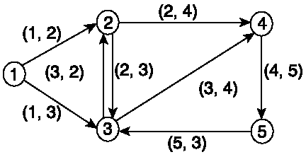
The set of arcs in Figure 6-1 can therefore be represented as {(1, 2), (1, 3), (2, 3), (2, 4), (3, 2), (3, 4), (4, 5), (5, 3)}. The set of vertices and set of arcs can be assigned lettered names as follows :
N = {1, 2, 3, 4, 5}, for the set of vertices
L = {(1, 2), (1, 3), (2, 3), (2, 4), (3, 2), (3, 4) (4, 5), (5, 3)}, for the set of arcs
The graph can be named G and represented as G = (N, L), where N is the set of vertices and L is the set of arcs.
A path is a sequence of similarly directed arcs between any two vertices in a graph. In Figure 6-1, for example, the path from vertex 1 to vertex 4 can be either the sequence (1, 2), (2, 4), or (1, 3), (3, 2), (2, 4). The objective of the SPF algorithm is to determine the shortest path from any reference vertex, s, to all other vertices in the graph. The SPF algorithm uses an iterative mechanism to solve the problem.
The next section shows the operation of the SPF algorithm for a directed graph represented by G = (N, L), given a fixed vertex, s, in the set N where
-
N Set of vertices
-
L Set of arcs
-
d(i, j) Distance from vertex i to j, where
-
- d(i, j) = infinity, if vertices i and j are not directly connected
-
-
P Set of vertices whose shortest paths from the reference vertex have already been determined
-
L(n) Current least cost from vertex s to vertex n
The algorithm determines the shortest path from reference vertex s to each vertex n in the graph. In general, three main steps are involved in the process:
-
Initialization
-
Selection of the next vertex
-
Update of least cost paths
Operation of the SPF Algorithm
The three primary steps in the operation of the SPF algorithm are elaborated as follows:
- Step 1. Set i = 0,P0 = {v0 = s}, L(s) = 0.
L(n) = d(s, n) if n is directly connected to s. L(n) = infinity for n not directly connected to s. Label each node n with [L(n),s]. set i = 1.
- Step 2. Find the next vertex vi not in P, which has L(vi) = min L(n), for all vi}. Move vi to P. New vertex is vi.
- Step 3. Update least cost paths of vertices not in P:
L(n) = min{L(n), L(vi)+d(vi,n)}.
If L(n) is replaced , update label on n to [L(n), NH(vi)], where NH(vi) is the next hop to vi from S.
Replace i by i+l, (i = i+l).
If i = N-i, stop; otherwise go to Step 2.
Step 1 is the initialization stage. Because the algorithm is iterative, it proceeds in stages, with each stage denoted by the value of i. At the initialization stage, i is set to 0. The computation is performed relative to a reference vertex, s. The reference vertex is also known as the source. Three separate lists are used in the operation of the algorithm:
Unknown (U) Set of vertices that haven't been considered yet
Tentative (T) Set of vertices under consideration
Paths (P) Set of vertices to which the shortest path has been computed
At initialization (i = 0), the reference vertex, v0 = s, is selected and placed in the set of known closest vertices (P)that is, P0 = {v0 = s}. The rest of the vertices in the graph are placed in set U. The cost of s to itself, L(s), is 0. The costs from s to directly connected vertices are set to their known values, whereas costs for vertices that are not directly known are considered unknown and, therefore, set to infinity.
In Step 2, the algorithm determines the next closest vertex to s from the set T, notes the associated cost and its next hop, and then promotes it to the set P. Initially, only the vertices directly connected to s are moved from the U set to T for consideration. The vertex with the lowest cost is promoted to the set P. When a vertex is promoted from T to P, all nodes directly connected to it are then placed in T for consideration, if they are not already there.
In the final step, the least cost associated with every node in T is updated relative to the most recent vertex promoted to P and the next hop is also changed to that of the promoted vertex. An existing least cost value is replaced only if the new valve is lower.
The algorithm then proceeds to the next iteration by going to Step 2 and continues through Step 3 again, until every node has been moved to the set P. For a graph with N vertices, including the reference vertex at which the calculation is centered, N-1 iterations exist starting at 0. At the end of the (N-1) iteration, the computation provides the shortest distance from the reference to all other vertices in the graph.
The determination of the shortest path between any two vertices in a digraph is analogous to finding the shortest path between any two nodes in a data communications network. As noted earlier, the function of routing protocols is to determine the shortest path between nodes in a network by some optimality criteria, frequently the least cost or lowest metric. In a perfect analogy, the routers in a communications network correspond to the vertices of a digraph, and the links or adjacencies correspond to the arcs. Because the traffic flow between network nodes is bidirectional, each network link corresponds to a pair of parallel arcs facing opposite directions. The links in a network are typically assigned weighted values referred to as costs or metrics. Most real networks apply scalar link costs, which are inversely proportional to bandwidth. Therefore, the fastest links are assigned smaller cost values. Finding the shortest path between nodes in a network, therefore, implies determining the least cost path between them. Other possible metric options are hop count and composite metrics. Composite metrics are based on the combined evaluation of bandwidth, delay, reliability, load, maximum transmission unit (MTU), and other link characteristics.
Computational Cost of the SPF Algorithm
The previous sections describe how the SPF algorithm works and indicate that the computational cost associated with the algorithm depend on the number of nodes and links involved. The SPF algorithm can be resource-intensive for large networks with the computation time required reaching an order of N^2, where N is the number of nodes. This order of complexity can be discerned intuitively considering that, for a total of N nodes, N-1 iterations are required to determine all the least cost paths from a reference node to all other nodes in the graph. At each iteration, the number of operations required to determine the vertex with the least cost is proportional to N.
If N nodes are in a graph and the total number of links in the graph is L, it can be shown that, in general, the SPF computation time is proportional to the number of linksL times the log of the number of links, L in the network. That is the computational cost of the SPF of the order, O(LlogL).
In nonhighly meshed networksfor example, where all nodes are interconnected with the fewest possible links in a linear arrangement, L equals to N-1. LlogL can be expressed as Llog(N-1), which is equivalent to LlogN. In summary, you can estimate the order of computational complexity of Dijkstra's SPF algorithm to be O(LlogN), where L is the total number of links and N is the number of nodes in the network. The computational complexity is directly related to the processing time required for execution to completion of the algorithm.
Another element of interest in the operation of the Dijkstra algorithm is storage or memory requirements.
Memory Requirements
Each router in the graph stores N LSPs, one from each node in the area. Because each LSP contains information about connected links and adjacent neighbors, the size of each LSP is proportional to K, the number of connected links. Therefore, each node needs storage space proportional to N*K links. That is, memory requirements at each node is of the order O(N*K) or O(L), where L is the total number of links. In a nonhighly meshed environments, where L is of the same order as the number of nodes (N), the memory requirements can be estimated to be of the order O(N).
Excessive memory requirements and the corresponding high processing time of the SPF algorithm for large numbers of nodes are the primary drivers for introducing hierarchy into the network design. IS-IS provides a two-level hierarchy that allows area explosion to be contained by building multiple reasonably sized Level 1 areas and gluing them together with a Level 2 backbone.
SPF Calculation Example
Table 6-1 illustrates the operation of the Dijkstra algorithm based on the graph in Figure 6-2. An animation that also illustrates in step-through manner the operation of the Dijkstra algorithm is at the following referenced Web site: http://ciips.ee.uwa.edu.au/~morris/Year2/PLDS210/dijkstra.html.
Figure 6-2. Topology for illustration of Dijkstra algorithm.
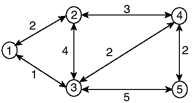
In Figure 6-2, bidirectional arrowed links are used for arcs and to imply same cost between adjacent nodes in either direction. This might not be the case in real networks. Specifically, IS-IS does not require matching metric values in both directions for the same link. The topology shown in Figure 6-2 has five nodes and seven links. The algorithm is performed using node 1 as the reference node. In a real network, each node performs a similar calculation by using itself as the reference. The goal is to obtain the least cost (best) path from the source of the calculation to all other nodes in the topology.
The algorithm is initialized at i = 0. Column i represents the iterations. L(n) is the value of the current total cost from s to node n for a specific iteration. "next hop" is the directly connected next hop to get to a specific node. Other abbreviations in the table are as follows:
-
P The set of entries in the Paths set or list
-
(value) Directly connect next hop from S
Table 6-1. Example of Dijkstra's Calculation (s = 1)
| Node 1 | Node 2 | Node 3 | Node 4 | Node 5 | ||
|---|---|---|---|---|---|---|
| i | P | L(1), next hop | L(2),next hop | L(3),next hop | L(4),next hop | L(5), next hop |
| {1} | 0 (1) | 2 (2) | 1 (3) | Infinity | Infinity | |
| 1 | {1, 3} | - | 2 (2) | 1 (3) | - | - |
| 2 | {1, 3, 2} | - | 2 (2) | - | 3 (3) | 6 (3) |
| 3 | {1, 3, 2, 4} | - | - | - | 3 (3) | 6 (3) |
| 4 | {1, 3, 2, 4, 5} | - | - | - | - | 5 (3) |
Table 6-1 shows the paths that are selected from the Tentative set at every iteration in boldface. Only Nodes 2 and 3 are moved to the Tentative set in iteration i = 1. Each path shows the metric to the destination and the next hop. The next hops from node 1 to nodes 2 and 3 are nodes 2 and 3 themselves because they are directly connected.
Nodes that are not directly connected to s inherit the next hop of their parents. For example, the best path to get to node 4 is through node 3 with a cost of 3. The best path to node 5 is through node 4; however, the parent of node 4 is node 3. Therefore, node 3 becomes the next hop to get to node 5 from node 1. Note that the next-hop computation expresses the datagram forwarding paradigm, in which each node is interested only in the next hop as it forwards a packet toward the destination along the optimum path.
Explanation of Table 6-1 (SPF Calculation Example)
The steps in the operation of the SPF algorithm illustrated in Table 6-1 are explained here. The explanations follow the iterations in the example.
| 1 = 0 | In the first iteration, node 1 is selected as the source, and corresponding L(1) = 0 and NH = 1 are entered under node 1 to indicate the next hop from the source to node 1 is itself, and the cost is 0. No action is taken for the other nodes. |
| i = 1 | In iteration 1, nodes directly connected to node 1, which are nodes 2 and 3, are put into the T set. The next hop from node 1 to node 2 is node 2, and the cost is 2. The next hop from node 1 to node 3 is node 3 itself, and the cost is 1. Nodes 4 and 5 remain in the Unknown set and are assigned costs of infinity. Node 3 is promoted from T to P because it has the lowest cost. |
| i = 2 | After node 3 is promoted from T to P, its directly connected neighbors that are not yet in P, nodes 4 and 5, are entered into T. Note that node 2 is already there with a cost of 2. The path from the source to node 2 through 3 has a cost of 5, so the original entry is retained because it has a lower cost. Nodes 4 and 5 use node 3 as next hop from the source. The total cost from node 1 to node 4 is 3, and the corresponding cost to node 5 is 6. Node 2 is, therefore, promoted from T to P because it has the lowest cost. |
| i = 3 | After node 2 is promoted to P, its directly connected neighbors that are not yet in P are considered. This happens to be only node 4, which is already in T. The total cost from node 1 to 4 through node 2 is 5, so the previous path with lower cost is retained. Node 4 is promoted to P because it has a lower associated cost than node 5. |
| i = 5 | After node 4 is promoted to P, its directly connected neighbors that are not yet in P are considered. This happens to be only node 5. Node 5 is currently in T. However, the cost from node 1 to node 5 through 4 is lower than the previous cost of 6. Therefore, node 4 replaces node 3 as the parent of node 5. Also, node 5 inherits the next hop associated with node 4, which is coincidentally node 3. The next hop from node 1 to node 5 remains node 3, but the cost is reduced to 5. Because node 5 is the only node in T, it is promoted to P. |
Figure 6-3 shows the resulting least cost topology, at the end of the algorithm, as seen from the perspective of node 1. Nodes 2 and 3 are directly connected, but the best path to node 4 is through node 3, and the best path to node 5 is through node 3 and then node 4.
Figure 6-3. Least-cost topology from node 1.
EAN: 2147483647
Pages: 144