IS-IS Areas and Routing Hierarchies
As specified in ISO 10589 and RFC 1195, the IS-IS protocol supports a two-level hierarchy for managing and scaling routing in large networks. A network domain can be carved out in a planned way or arbitrarily by the network designer or architect into small segments known as areas. This allows hierarchical routing to be leveraged for efficient routing within the domain. Integrated IS-IS uses the legacy CLNP node-based addresses to identify routers even in pure IP environments. The CLNP addresses, which are known as Network Service Access Points (NSAPs), are made up of three components : an area identifier (area ID) prefix, followed by a system identifier (SysID), and an N-selector. The N-selector refers to the network service user , such as a transport protocol or the routing layer. It has similar interpretation as the application port number used in the IP Transmission Control Protocol (TCP). The CLNP addressing scheme is introduced later in this chapter (see the section "Addressing Concepts in Integrated IS-IS") and discussed further in detail in Chapter 4, "Addressing in Integrated IS-IS."
For now, just remember that each IS-IS router has a unique SysID, which together with the area ID and an N-selector value of 0x00 forms a special NSAP known as the node's network entity title (NET).
A group of routers belong to the same area if they share a common area ID. Note that all routers in an IS- IS domain must be associated with a single physical area, which is determined by the area ID in the NSAP. In practice, an IS-IS router can be configured with multiple NSAPs all with different area IDs and same SysID in situations where the router is " homed " to multiple areas. As discussed later, however, multihoming merges all the areas involved into a single physical area. Routers belonging to a common area and engaged in Level 1 routing are referred to as Level 1 routers. In CLNP routing, Level 1 routing involves collecting SysID and adjacency information through all routers and hosts in the local area. Routers in different areas exchange routing information through Level 2 routing and are referred to as Level 2 or backbone routers. In CLNP Level 2 routing, routers exchange area prefix information with their peers. For IP routing, however, intra-area IP prefixes are exchanged within the area in Level 1 routing. The IP prefixes originated in the various areas are then exchanged between areas in Level 2 routing by routers connected to the backbone.
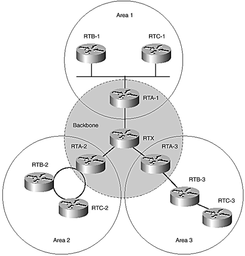
In most designs with routing hierarchy, the Level 2 routers are also Level 1 routers by virtue of their identification with a certain area. Therefore, in IS-IS, a router can function as Level 1-only or Level 2-only and possibly as both Level 1 and Level 2 (Level 1-2). Level 1-2 routers act as border routers to their respective areas, providing connectivity to other areas. The Level 2 backbone is essentially a virtual IS-IS area consisting of routers engaged in Level 2 routing (see Figure 3-1). The Level 2 stretch in a network must be contiguous, requiring all routers to be interconnected . Because partition repair is not supported in Cisco IOS and most other implementations , the contiguity requirement also applies to Level 1 areas. In a hierarchical network, some Level 2-only routers could be embedded in the backbone without impacting traffic flow between the respective areas supported by Level 1-2 routers. Existing IS-IS specfications require only Level 2 routers to provide connectivity to external domains; however, Cisco IOS allows redistribution of external routes into Level 1 for historical and practical reasons.
Figure 3-1. IS-IS areas.

Level 1-only routers are aware of the local area topology only, which involves all the nodes in the area and the next -hop routers to reach them. Level 1 routers depend on Level 2 routers for access to other areas and forward all traffic to destinations outside the area to the closest Level 2 router.
Cisco routers running IS-IS can be configured to be either Level 1-only, Level 2-only, or both. By default, they are both Level 1 and Level 2, and special configuration is required to disable Level 1 or Level 2 capability. Caution must be exercised when disabling either capability because this might introduce disruptive inconsistencies into the routing environment. In Figure 3-1, routers RTA-1, RTA-2, RTA-3, and RTX must be Level 2-capable to participate in routing between the areas. RTX can be in its own dedicated area and because it doesn't connect to any Level 1 routers, it can be configured to be Level 2-only. However, the others must be Level 1-2 and each identified with a specific area for which it provides interarea connectivity. RTB-n, RTC-n (n = 1,2,3) can be configured to be Level 1-only if they don't need to connect to the backbone.
EAN: 2147483647
Pages: 144
- ERP Systems Impact on Organizations
- Enterprise Application Integration: New Solutions for a Solved Problem or a Challenging Research Field?
- Context Management of ERP Processes in Virtual Communities
- Relevance and Micro-Relevance for the Professional as Determinants of IT-Diffusion and IT-Use in Healthcare
- Development of Interactive Web Sites to Enhance Police/Community Relations