Overview of Processor Characteristics
| Before delving into management details, we need to review the basic architecture of a Cisco router and Catalyst switch. NOTE Please note that not all platforms are covered in this chapter due to the lack of public information available at the time of this writing. For more details regarding other Cisco platforms, such as the 12000 series routers or the 6000 and 8500 series Catalyst switches, refer to Cisco Connection Online, or CCO, and the product literature. The purpose of this chapter is not to educate you on the architecture, but to give you a general understanding about what is important when looking at performance and fault management. Router ProcessorsBecause each Cisco router model acts differently, depending on processor speed and features, a useful first step in this overview is to identify what is common to all platforms and pinpoint some of the differences. The most common variable on the processors is the IOS, or the software running on the router. All Cisco routers run IOS software, except for the 700 series access routers. The majority of the MIBs and CLI (command-line interface) commands for all IOS-based routers give you roughly the same output format across all platforms. There are additional features on certain routers that relate only to that platform. For example, the Netflow feature is supported only on the 7200 and 7500 series routers, whereas only the 2500 series routers support all nine groups of RMON. The processors on routers contain system DRAM memory, shared (I/O) memory (platform-specific), flash memory, NVRAM, MAC addresses for the interfaces, and environmental monitoring statistics. On high-end routers, such as the 7xxx series, shared (I/O) memory is either broken out from system DRAM memory, SRAM (RSP4), or by a separate card called the SP (or switch processor), as seen in the 7000 series routers. Mid-range and low-end routers, such as the 4xxx, 2500, 2600, 3600, and 1600 series, have separate I/O memory from system memory, either physically on a different DRAM chip or partitioned independently on the system memory DRAM chip. More details regarding memory follow later in the section entitled "Router Memory." Some interface processors on the high-end routers have their own processor and memory. These cards are called VIPs, or versatile interface processors, and are supported on the RSP platform routers. A subset of the IOS is loaded on these cards from the main IOS image residing on the main RSP. The memory installed on these cards is allocated to the data packets coming and going from the individual port adapters installed on the VIP. The more detailed statistics for these cards, such as diagnostics, are accessible through a Telnet session via the RSP, using the CLI command if-con <slot>. if-con presents the user with an interface similar to that of the CLI prompt. From that prompt, you can execute show commands equivalent to the normal CLI prompt. NOTE if-con is considered a hidden command and is not supported by Cisco, but it does provide useful information such as VIP CPU usage: show proc cpu. The VIP cards also perform distributed switching, which cannot be done elsewhere on the router. Catalyst Switch ProcessorsThere are currently three different types of processors, or supervisor engines, for the Catalyst series switches, excluding the 1200 and 8500 series. Each one is basically an enhancement of the other, starting with the Supervisor I (WS-5005, WS-C5006, and WS-C5009), then the Supervisor II (WS-C5505, WS-C5506, and WS-C5509), and then the Supervisor III (WS-C5530). Table 11-1 provides a breakdown comparison of each. NOTE Please note that the 6500 series and 8500 series switches are not covered here, but the Supervisor cards for those switches resemble that of the Supervisor III. The purpose of Table 11-1 is to give you an idea of what you're looking for on the Supervisor cards. The same methodology can be applied to the 6500 and 8500 series switches. For more information on the 6500 and 8500 series architecture, refer to CCO.
For more details on the logical port calculation and VLANs, see Chapter 15, "Monitoring VLANs." All the Supervisor versions support up to 16,000 MAC addresses in the CAM table and a maximum of 1024 VLANs. The Supervisor II and III have extra key features, such as redundant Supervisor cards, and the use of the NetFlow Feature Card (NFFC) for Layer 3 switching. The Supervisor IIG and IIIG models include the NFFC on the card and do not require an additional daughter card. A switch performs most of the packet forwarding without impacting the CPU. As such, measuring the CPU of a switch is of little importance when determining the switch's packet-forwarding performance. Therefore, we do not cover trending or monitoring the switch CPU in the performance and fault/error management sections of this chapter. Switching decisions are performed on the switch ASICs and, depending on the switch type, the bridging table may be stored on an ASIC as well. Some of the operations performed by the switch's CPU include spanning tree, Telnet services, Cisco Discovery Protocol (CDP), security (such as Terminal Access Controller Access Control System [TACACS]), remote monitoring (RMON), VLAN Trunk Protocol (VTP), port aggregation, dynamic VLANs, and SNMP processing. If anything makes the CPU busy on the switch, it is broadcast and multicast traffic. This is usually caused by the VLAN assignment to the sc0 port on the switch. For more details on best practices regarding the configuration of the switch, see Chapter 18, "Best Practices for Device Configuration." Router Switching PathsDepending on the router platform you have, different switching paths are available, especially when you get into the high-end routers such as the 7500s or 7200 series. All router platforms have the capability of performing process switching or fast switching of packets. Through the switching process, the router determines the next hop toward the destination address. Switching moves traffic from an input interface to one or more output interfaces. Switching is optimized and has lower latency than routing because it can move packets, frames, or cells from buffer to buffer with simpler determination of the source and destination of the traffic. It saves resources because it does not involve extra lookups. Reduced latency can be attributed to the following factors:
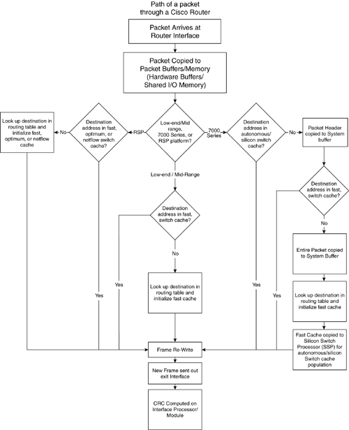
Figure 11-1 shows the path of a packet through the router. Figure 11-1. Path of a Packet Through a Router
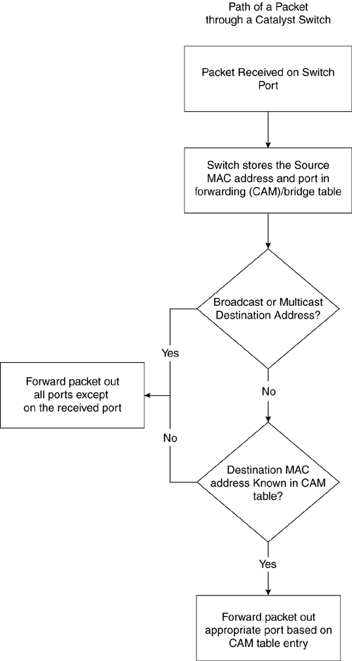
If you want to view the switching path of packets through a router, you can execute the CLI command show interface switch. Process SwitchingIn process switching, the first packet that enters a router's interface is copied to the system buffer. The router looks up the Layer 3 network address in the routing table and initializes the fast-switch cache. The frame is rewritten with the destination address and sent to the exit interface, where the destination resides. Subsequent packets for that destination are sent by the same switching path. Fast SwitchingIn fast switching, the first packet is process switched. The router then caches some of the IP or other Layer 3 header, the new Layer 2 header, and the internal index of the outbound interface. Subsequent packets can then be compared against the cached Layer 3 information. If a match is found, the Layer 2 header replaces the existing Layer 2 header without moving the packet around in memory, and the outbound interface information is then used to queue the packet for output. Fast switching is enabled by default on all interfaces that support fast switching, except on the 7500 series routers, where optimum switching is the default. Optimum SwitchingOptimum switching is similar to the format of fast switching, but is a bit faster because it utilizes the associative array capabilities of the RISC processor. The cache entry is found a lot faster by the processor due to this array structure. Optimum switching is enabled by default on Cisco 7500 series routers and first appeared in IOS 11.1. Distributed SwitchingIn distributed switching, the switching process occurs typically on the VIP (Versatile Interface Processor). The VIP card maintains a copy of the routing cache information needed to forward packets. Because the VIP card has the routing information it needs, it performs the switching locally, making the packet forwarding much faster and much more efficient. Router throughput is increased linearly, based on the number of VIP cards installed in the router. Distributed switching is supported on the Cisco 7500 series and 12000 Series routers. NetFlow SwitchingNetFlow switching enables you to collect the data required for flexible and detailed accounting, billing, and chargeback for network and application resource utilization. Accounting data can be collected for both dedicated line and dial-access accounting. NetFlow provides an optimized code path that allows for efficient statistics collection as well as access list processing. NetFlow switching is supported on the Cisco 7200 and 7500 series routers. NetFlow switching is also supported over switched LAN or ATM backbones, allowing scalable inter-VLAN forwarding. Catalyst Switch Switching PathsAll Catalyst 5xxx and 29xx series switches (excluding the IOS-based 2900XLs) utilize the store-and-forward approach to delivering packets. The store-and-forward switching mode stores complete packets and checks for errors prior to transmission. In store-and-forward mode, latency is measured as last-bit-received to first-bit-transmitted or "Last-In, First-Out" (LIFO). This does not include the time it takes to receive the entire packet, which can vary, according to packet size. The time required to receive a packet at 100 Mbps varies between 51.2 microseconds and 1.2 milliseconds. At 10 Mbps, the time required to receive a packet varies between 5.12 microseconds to 120 microseconds. The cut-through technology as seen on the 3000 series switches is faster, but may introduce the forwarding of bad packets because the packet is not checked for errors when switched. Figure 11-2 is an illustration of the path of a packet through a switch. Figure 11-2. Path of a Packet through a Switch
Router MemoryThere are different types of memory in routers: System DRAM, I/O memory, Flash, and NVRAM. The following sections briefly describe what each one does and how each one functions in the router. System MemoryWhen a router initially boots up, the IOS image running on the router must first be loaded into system memory prior to any other process gaining access to this memory pool. This holds true for all routers except for some of the 2500 series routers, in which the IOS image is run from flash and is never loaded into main system memory. After the IOS image is decompressed and loaded, all the router's processes can begin to utilize the rest of main system memory. TIP The IOS image stored on flash is smaller in size than the image stored in RAM due to the compressed nature of the flash memory file. Make sure you take that into consideration when looking at system memory requirements. This division of system memory explains why your "Total memory available" on the router never equates to the amount of system memory installed. This difference can be verified by executing the show memory command on the router, as shown in Example 11-1. Example 11-1 The show memory command reveals that total memory available and amount of memory installed are not equivalent.Router>sh mem Head Total(b) Used(b) Free(b) Lowest(b) Largest(b) Processor 60DC38E0 52676384A 1801772 50874612 50862952 50873820 Fast 60DA38E0 131072 48184 82888 82888 82844 ... ... Router>show ver ... cisco RSP2 (R4700) processor with 65536KB/2072K bytes of memory. R4700 processor, Implementation 33, Revision 1.0 Last reset from power-on G.703/E1 software, Version 1.0. G.703/JT2 software, Version 1.0. SuperLAT software copyright 1990 by Meridian Technology Corp). Bridging software. X.25 software, Version 2.0, NET2, BFE and GOSIP compliant. TN3270 Emulation software (copyright 1994 by TGV Inc). ... ... Router>sh flash -#- ED --type-- --crc--- -seek-- nlen -length- ----------date/time------ name 1 .. FFFFFFFF 674BED34 11A1B20 24 6994832 Jan 28 1999 rsp-jv-mz.111-18.CA1.bin This image, rsp-jv-mz.111-18.CA1.bin, equals 12859616 bytes uncompressed, or 65536000 bytes(B) minus 52676384 bytes (A). More details regarding system memory characteristics and monitoring follow in the section "MIB Variables for Memory Utilization on Routers," especially relating to free memory, contiguous free memory, and process memory allocation based on the CISCO-MEMORY-POOL-MIB, show mem CLI command, and show proc mem CLI command. I/O MemoryOne of the first things the router does after booting up is allocate hardware buffers for the interfaces on the router. The buffers typically are distributed via the Cbus architecture (RSP, SP, or SSP cards) on the high-end routers, such as the 7xxx series; or by the I/O memory on the low-end routers, such as the 4xxx, 3600, and 2500 platforms. I/O memory is physically separated from the system memory on the low-end routers (4xxx, 3600, 2500 series, etc.) and requires a separate memory SIMM to be installed. The core routers, or high-end 7xxx series routers, use portions of their system memory to allocate hardware buffers. These hardware or MEMD buffers are allocated based upon media interface bandwidths and MTUs. Here's the process:
The final resulting values for each interface can be validated by executing the CLI command show controller. Refer to annotated item A in Example 11-2 to see where the interface buffers are reported. For more details on hardware buffers, see the section entitled "Hardware Buffers" in Chapter 10, "Managing Hardware and Environmental Characteristics." Example 11-2 shows the output for both a low-end router and a high-end router. Example 11-2 Using the show controller command to view the buffers allocated to the interfaces on the router. Router4500>show controller AM79970 unit 0 NIM slot 2, NIM type code 22, NIM version 1 Media Type is AUTOSELECT, 10BaseT selected, Half Duplex, Link State is Up, Squelch is Normal idb 0x60CADD14, ds 0x60CAF900, eim_regs = 0x3C210000 IB at 0x4003ED50: mode=0x0010, mcfilter 0000/0008/0100/0020 station address 00e0.1e4d.18c2 default station address 00e0.1e4d.18c2 buffer size 1524A RX ring with 32 entries at 0x4003E2E8 Rxhead = 0x4003E328 (8), Rxp = 0x60CAF938 (8) 00 pak=0x60CBB11C ds=0xA810AFAA status=0x80 max_size=1524 pak_size=92 01 pak=0x60CB7684 ds=0xA80FE5A2 status=0x80 max_size=1524 pak_size=300 ... ... High-end 7500 series router output is as follows: Router7500>sh controller cbus MEMD at 40000000, 2097152 bytes (unused 128, recarves 1, lost 0) RawQ 48000100, ReturnQ 48000108, EventQ 48000110 BufhdrQ 48000120 (2353 items) IpcbufQ_classic 48000140 (8 items, 4096 bytes) 3570 buffer headers (48002000 - 4800FF10) pool0: 9 buffers, 256 bytes, queue 48000128 pool1: 1196 buffers, 1536 bytes, queue 48000130 pool2: 4 buffers, 1568 bytes, queue 48000138 slot0: EIP, hw 1.10, sw 20.05, ccb 5800FF20, cmdq 48000080, vps 4096 software loaded from system Ethernet0/0, addr 0090.f2d0.e000 (bia 0090.f2d0.e000) gfreeq 48000130, lfreeq 48000148 (1536 bytes) rxlo 4, rxhi 1196, rxcurr 0, maxrxcurr 2A txq 48000150, txacc 48000082 (value 797), txlimit 797A Ethernet0/1, addr 0090.f2d0.e001 (bia 0090.f2d0.e001) gfreeq 48000130, lfreeq 48000158 (1536 bytes) rxlo 4, rxhi 1196, rxcurr 0, maxrxcurr 0 txq 48000160, txacc 4800008A (value 797), txlimit 797 ... ... High-end 7000 series router output is as follows: Router7000>sh controller cbus Switch Processor 5, hardware version 12.0, microcode version 11.15 Altera 0 Microcode loaded from system 512 Kbytes of main memory, 128 Kbytes cache memory 4 256 byte buffers, 4 1024 byte buffers, 312 1520 byte buffersA Restarts: 0 line down, 0 hung output, 0 controller error ... ... Flash Memory and NVRAMFlash memory in the routers is responsible for storing the IOS image, Interface Processor microcode, and sometimes the router's configuration. Flash memory is either on the processor board or on a PCMCIA card that is installed on the router. The newer generation routers have Flash on the PCMCIA flash cards versus directly on the system board. NVRAM typically is where the router configuration file is stored and usually has a size of 256 KB or 512 KB much smaller than the Flash memory. Switch MemoryMemory on the Catalyst switches works a bit differently than on the router. The "I/O" equivalent memory is fixed for each port on the switch to a 192 KB buffer. The system memory on the switch Supervisor card is used mainly for the CAM or bridging table and can safely store 16,000 MAC entries. A portion of the system memory is allocated to the buffers and clusters of the switch, called mbufs. Mbufs are discussed next, under "Router Buffers." The flash memory on the switch is used for the software image; the NVRAM is used for the configuration file and logging, both syslog output and show log output. Router BuffersWe already discussed how hardware buffers are allocated in routers in Chapter 10. This section focuses on how the system buffers work in the routers. System buffers are broken out into six different types, as summarized in Table 11-2.
These system buffers only affect process switched traffic through the router. Each buffer type is allocated a fixed amount of permanent buffers at boot time. These values can be overwritten based on the presence of the buffer permanent command in the configuration of the router. Permanent buffers are the number of buffers the system tries to create and keep, and are normally not trimmed by the system. Any packets hitting these system buffers are process-switched packets, such as routing updates, broadcasts, explorers, etc. Here are some terms and definitions relating to router buffers:
These variables are analyzed in more depth later in the section called "Performance Data for Router Processors." For more information regarding buffers, refer to the online documentation on CCO. Switch BuffersMbufs are fixed buffers on the switches and are permanently set. They come in two "flavors:" mbuf and clusters. Each mbuf is segmented into 128 bytes (116 data bytes) whereas clusters are packets greater than 1664 bytes (13 mbufs and 1508 data bytes). The only traffic that affects the mbuf and cluster counters is traffic destined to the supervisor engine, such as BPDUs, VTP, or CDP. The critical values that need to be looked at with switch buffers are the "free" and "lowest free" mbufs and clusters because they can help identify possible memory leaks or lack of proper memory resources. These values can be validated by executing the CLI "enable" command show mbuf. |
EAN: 2147483647
Pages: 200