Lesson 2: Connection Services
In Lesson 1, we examined devices that allow us to extend a LAN. As our networks grow, they quickly exceed the capacity of standard network media, and it is no longer practical to run our own cabling, especially if one of the nodes is located across the street or in another state. In this lesson, we explore the various connection services that we can employ with the hardware discussed in Lesson 1 to extend a network.
This lesson examines connection service options. Many network connection choices are available, and each has advantages and disadvantages. We begin with simple telephone lines and move on to cover high-speed digital services.
After this lesson, you will be able to:
- Describe the principles behind moving data quickly and economically across long distances.
- Describe the difference between analog and digital communication.
- Describe how packet switching works.
- Identify the primary features of each of the following: X.25, frame relay, ATM, ISDN, FDDI, SONET, and SMDS.
Estimated lesson time: 45 minutes
Carriers
A modem is useless unless it can communicate with another component. All modem communication takes place over some kind of communication line or cable. Which type of cable it is, as well as who provides it and its related services, makes a difference in network performance and cost.
The issue is simple: it is difficult and expensive to move data quickly over long distances. The three factors an administrator must take into account when considering how to implement modem communications are:
- Throughput.
- Distance.
- Cost.
You need to apply these factors when deciding which type of telephone lines to install for your network.
Telephone Lines
Two types of telephone lines are available for modem communications:
Dial-Up Lines
Dial-up lines are common telephone lines. They are slow, require users to make a connection for each communication session manually, and can be unreliable for transmitting data. However, for some companies it may be practical to temporarily use a dial-up communication link between sites for a certain amount of time each day to transfer files and update databases.

Run the c07dem16 video located in the Demos folder on the CD accompanying this book to view a presentation of a dial-up communication link.
Carriers are continually improving their dial-up line service. Some digital lines support data transmission speeds of up to 56 Kbps using error correction, data compression, and synchronous modems.
Leased (Dedicated) Lines
Leased, or dedicated, lines provide full-time, dedicated connections that do not use a series of switches to complete the connection. The quality of the line is often higher than the quality of a telephone line designed for voice transmission only. They typically range in speed from 56 Kbps to 45 Mbps or more.
Run the c07dem17 video located in the Demos folder on the CD accompanying this book to view a presentation of leased (dedicated) lines.
Most long-distance carriers use switched circuits to provide what appears to be a dedicated line. These are called "virtual private networks" (VPNs).
Remote Access Service (RAS)
Frequently, businesses need to be able to communicate beyond the bounds of a single network. Most server-based network operating systems provide a service, called Remote Access Service (RAS), to meet that need. To establish a remote connection requires two services: RAS and a client service known as dial-up networking (DUN). The server or workstation uses RAS to link remote computers to the network by means of a dial-in connection over a modem. DUN, the other side of the service, is used by remote computers to connect to the RAS server. Together, these two services provide the ability to extend a network and can, in effect, convert a LAN into a WAN. Because many Internet service providers use telephone-line access, a RAS server often serves as an Internet interface for its network.
NOTE
The key difference between RAS service on a server computer and on a client computer lies in the number of simultaneous connections allowed. For example, a Windows NT Server allows 256 inbound connections, whereas a Windows NT Workstation client allows only one.
Separate computers and LANs can be connected to each other over the Public Switched Telephone Network, packet-switched networks, or Integrated Services Digital Network; (these services are discussed later in this lesson).
Once a user has made a connection, the telephone lines become transparent (invisible to—not perceived by—the user), and users at the remote client can access all network resources just as they would if they were sitting at their computers at the network site. Figure 7.20 shows a remote client connected to a network server using RAS.
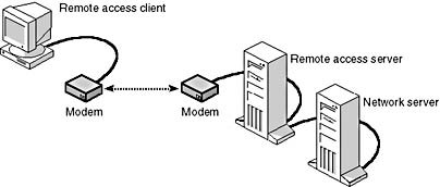
Figure 7.20 RAS allows remote users to access the network
RAS Connections
The physical connection to a RAS server can be made using several different media. These include the following:
- Public Switched Telephone Network (PSTN) This service is otherwise known as the public telephone system.
- X.25 This packet-switched network service can be used to make dial-up or direct connections.
- Integrated Services Digital Network (ISDN) This service provides high-speed remote access, but at greater cost than a dial-up connection. An ISDN connection requires an ISDN card in place of a modem.
RAS Protocols
RAS supports three connection protocols. The oldest, dating from 1984, is the Serial Line Interface protocol (SLIP). It has a number of shortcomings. SLIP does not support dynamic IP addressing or the NetBEUI or IPX protocols, it cannot encrypt logon information, and it is supported only by RAS clients.
Point-to-Point Protocol (PPP) overcomes many of the limitations of SLIP. In addition to TCP/IP, it supports the IPX, NetBEUI, AppleTalk, and DECnet protocols. It also supports encrypted passwords.
Point-to-Point Tunneling Protocol (PPTP) is an essential part of VPN technology. Like PPP, it does not discriminate among protocols. PPTP provides secure transmission over TCP/IP networks because its connections are encrypted. This enables highly private network links over the public Internet.
RAS and Security
The actual methods by which RAS ensures security can vary with the operating system. RAS security functions include:
- Auditing An audit trail can be kept that identifies users and the times during which they logged on.
- Callback RAS can be configured to call back to the host that is requesting a connection, and the list of those host telephone numbers can be restricted to prevent unauthorized use of the system.
- Security host A security host can require additional authentication steps in addition to those that exist on the host's network.
- PPTP filtering This filtering process can prevent processing of any packets except PPTP. This provides a secure transfer of data over a VPN, preventing intruders from accessing the server.
Installing RAS
To plan for a RAS installation, begin by gathering appropriate documentation about the network and its users. Information you will need includes:
- Modem specifications, drivers, and settings (you will need a RAS-capable modem).
- Type of communication port to be configured.
- Whether this connection will be dial-in, dial-out, or both.
- Client protocols.
- Security requirements.
Configuring RAS
After RAS is installed, it has to be configured. Be prepared to provide settings for the communication ports, network protocols, and RAS encryption.
Configuring Dial-Up Networks If the server will be used to dial other networks, the Internet, or other computers, these connections must be configured. The method of configuration depends on the computer and network operating systems in use.
Limitations of RAS
Using a RAS connection is not always the best choice to achieve network expansion. But it does provide many features and opportunities that might not be otherwise available. It is important to know when to choose RAS and when to select a different option.
Use RAS if you determine that your bandwidth requirements are not greater than 128 Kbps, if you do not require a full-time connection, or if you must keep system costs down. Do not use RAS if you need a higher bandwidth than that provided by an asynchronous modem or if you need a dedicated full-time connection.
Point-to-Point Tunneling Protocol (PPTP)
This protocol supports multiprotocol VPNs. This support allows remote clients to connect and access the organizations network securely via the Internet. Using PPTP, the remote client establishes a connection to the RAS server on the Internet using PPTP.
PPTP provides a way to route IP, IPX, or NetBEUI point-to-point protocol packets over a TCP/IP network. By encapsulating these dissimilar protocol packets, any of these packets can be sent over the TCP/IP network. This virtual WAN is supported through the public networks such as the Internet.
WAN Overview
While LANs work well, they have physical and distance limitations. Because LANs are not adequate for all business communication, they must be able to connect between LANs and other types of environments to ensure access to full communication services.
Using components such as bridges and routers, along with communications service providers, a LAN can be expanded from an operation that serves a local area to encompass a wide area network that can support data communications statewide, countrywide, or even worldwide. To the user, the WAN appears to function like a local area network. When a WAN has been properly implemented, it appears indistinguishable from a LAN.
Most WANs are combinations of LANs and other types of communications components connected by communication links called "WAN links." WAN links can include:
- Packet-switching networks.
- Fiber-optic cable.
- Microwave transmitters.
- Satellite links.
- Cable television coaxial systems.
Because WAN links, such as wide-area telephone connections, are too expensive and complex for most private companies to purchase, implement, and maintain on their own, they are usually leased from service providers.
Communication between LANs will involve one of the following transmission technologies:
- Analog
- Digital
- Packet switching
Each of these technologies is described in detail in this lesson.
Analog Connectivity
The same network that your telephone uses is available to computers. One name for this worldwide network is the Public Switched Telephone Network (PSTN). In the context of computing, the PSTN, offering voice-grade dial-up telephone lines, can be thought of as one large WAN link.
Dial-Up Lines
The fact that the PSTN was designed primarily for voice-grade communication makes it slow; dial-up analog lines require modems that can make them even slower. Figure 7.21 shows a typical dial-up connection. Because the PSTN is a circuit-switched network, the connection quality is inconsistent. Any single communication session will be only as good as the circuits linked for that particular session. Over long distances—country to country, for example—there can be considerable inconsistency in the circuits from one session to the next. With ADSL technology becoming more available, improvements are likely to be made to dial-up lines in the future.
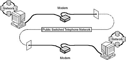
Figure 7.21 An analog telephone line can connect two computers using modems
Dedicated Analog Lines
Unlike dial-up lines that must be reopened each time they are used, dedicated (or leased) analog lines remain open at all times. A leased analog line is faster and more reliable than a dial-up connection. However, it is also relatively expensive, because the carrier is dedicating resources to the leased connection whether or not the line is being used.
Dial-Up or Dedicated?
No type of service is best for all users. The best choice will depend on a number of factors including:
- The amount of time the connection will be used.
- The cost of the service.
- The importance of having higher or more reliable data rates from a conditioned line.
- The need for a 24-hour-a-day connection.
If the need for connectivity is infrequent, dial-up lines can work well. If the connection needs a high level of reliability and usage will be fairly continuous over the month, then the service quality provided by a dial-up line might not be adequate.
Digital Connectivity
In some cases, analog lines provide sufficient connectivity. However, when an organization generates so much WAN traffic that the transmission time makes an analog connection inefficient and expensive, it might be time to consider alternatives.
Organizations requiring a faster, more secure transmission environment than that which analog lines provide can turn to digital data service (DDS) lines. DDS provides point-to-point synchronous communication at 2.4, 4.8, 9.6, or 56 Kbps. Point-to-point digital circuits are dedicated circuits that are provided by several telecommunications carriers. The carrier guarantees full-duplex bandwidth by setting up a permanent link from each endpoint to the LAN.
The primary advantage of digital lines is that they provide transmission that is nearly 99 percent error free. Digital lines are available in several forms, including DDS, T1, T3, T4, and switched 56.
Because DDS uses digital communication, it does not require modems (See Figure 7.22). Instead, DDS sends data from a bridge or router through a device called a Channel Service Unit/Data Service Unit (CSU/DSU). This device converts the standard digital signals that the computer generates into the type of digital signals (bipolar) that are part of the synchronous communication environment. It also contains electronics to protect the DDS service provider's network.
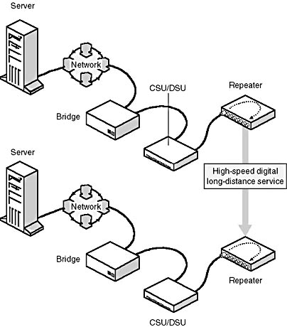
Figure 7.22 Digital data service line connecting two remote networks
T1 Service
For higher data speeds, T1 service is perhaps the most widely used type of digital line. It is a point-to-point transmission technology that uses two-wire pairs (one pair to send and the other to receive) to transmit a full-duplex signal at a rate of 1.544 Mbps. T1 is used to transmit digital voice, data, and video signals.
T1 lines are among the most costly of all WAN links. Subscribers who do not need or cannot afford the bandwidth of an entire T1 line can subscribe to one or more T1 channels in 64 Kbps increments, known as Fractional T-1 (FT-1).
Outside the United States, T1 service might not be available, but a similar service, called E1, often is. E1 is very similar to T1, but has a signaling rate of 2.048 Mbps.
Multiplexing Developed by Bell Labs, T1 uses technology called multiplexing, or "muxing." Several signals from different sources are collected into a component called a multiplexer and fed into one cable for transmission. At the receiving end, the data is demultiplexed back into its original form. This approach emerged when telephone cables, which carried only one conversation per cable, became overcrowded. The solution to the problem, called a T-Carrier network, enabled Bell Labs to carry many calls over one cable.
Dividing the Channel A T1 channel can carry 1.544 megabits of data per second, the basic unit of T-Carrier service. T1 divides this into 24 channels and samples each channel 8000 times per second. Using this method, T1 can accommodate 24 simultaneous data transmissions over each two-wire pair.
Each channel sample incorporates eight bits. Because each channel is sampled 8000 times per second, each of the 24 channels can transmit at 64 Kbps. This data rate standard is known as DS-0. The 1.544 Mbps rate is known as DS-1.
DS-1 rates can be multiplexed to provide even greater transmission rates, known as DS-1C, DS-2, DS-3, and DS-4. These have the transmission rates listed in Table 7.3 that follows:
Table 7.3 Digital Transmission Rates
| Signal level | Carrier system | T-1 channels | Voice channels | Data rate (Mbps) |
|---|---|---|---|---|
| DS-0 | N/A | N/A | 1 | 0.064 |
| DS-1 | T1 | 1 | 24 | 1.544 |
| DS-1C | T-1C | 2 | 48 | 3.152 |
| DS-2 | T2 | 4 | 96 | 6.312 |
| DS-3 | T3 | 28 | 672 | 44.736 |
| DS-4 | T4 | 168 | 4032 | 274.760 |
Copper wire will accommodate T1 and T2. However, T3 and T4 require a high-frequency medium such as microwave or fiber-optic cable.
T3 Service
T3 and Fractional T-3 leased line service provides voice and data-grade service from 6 Mbps to 45 Mbps. These offer the highest-capacity leased-line service commonly available today. T3 and FT-3 are designed for transporting large volumes of data at high speed between two fixed points. A T3 line can be used to replace several T1 lines.
Switched 56 Service
Both local and long-distance telephone companies offer Switched 56 Service, a LAN-to-LAN digital dial-up service that transmits data at 56 Kbps. Switched 56 is merely a circuit-switched version of a 56-Kbps DDS line. The advantage of Switched 56 is that it is used on demand, thereby eliminating the expense of a dedicated line. Each computer using this service must be equipped with a CSU/DSU that can dial up another Switched 56 site.
Packet-Switching Networks
Because packet technology is fast, convenient, and reliable, it is used to transmit data over extensive areas such as across cities, states, or countries. Networks that send packets from many different users along many different possible paths are called "packet-switching networks" because of the way they package and route data.
How Packet Switching Works
The original data package is broken into packets, and each packet is tagged with a destination address and other information. This makes it possible to send each packet separately over the network.
In packet switching, as shown in Figure 7.23, packets are relayed through stations in a computer network along the best route currently available between the source and the destination.
Each packet is switched separately. Two packets from the same original data package can follow completely different paths to reach the same destination. The data paths selected for individual packets are based on the best route open at any given instant.
Even when each packet travels along a different path and the packets composing a message arrive at different times or out of sequence, the receiving computer is still able to reassemble the original message.
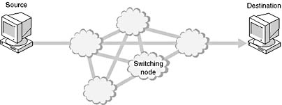
Figure 7.23 Simple packet-switching network
Switches direct the packets over the possible connections and pathways. These networks are sometimes called any-to-any connections. Exchanges in the network read each packet and forward them along the best route available at that moment.
Packet size is kept small. If there is an error in transmission, retransmitting a small packet is easier than retransmitting a large packet. Also, small packets tie up switches for only short periods of time.
Using packet-switching networks to send data is similar to shipping vast quantities of merchandise by truck instead of loading it all onto one train. If a problem should arise with the merchandise on one truck, it is easier to fix or reload than it would be to clean up the mess after a train runs off the track. Also, single trucks do not tie up crossings and intersections (switches) as trains do.
Packet-switching networks are fast and efficient. To manage the tasks of routing traffic and assembling and disassembling packets, such networks require some intelligence from the computers and software that control delivery. Packet-switching networks are economical because they offer high-speed lines on a per-transaction basis instead of for a flat-fee rate.
Virtual Circuits
Many packet-switching networks use virtual circuits. These are circuits composed of a series of logical connections between the sending computer and the receiving computer. The circuit is bandwidth allocated on demand, not an actual cable or permanent, physical link between two stations. The connection is made after both computers exchange information and agree on communication parameters that establish and maintain the connection. These parameters include the maximum message size and the path the data will take.
Virtual circuits incorporate the following communication parameters to ensure reliability:
- Acknowledgments
- Flow control
- Error control
Virtual circuits can last either as long as the conversation lasts (temporary) or as long as the two communicating computers are up and running (permanent).
Switched Virtual Circuits (SVCs) In Switched Virtual Circuits (SVCs), the connection between end computers uses a specific route across the network. Network resources are dedicated to the circuit, and the route is maintained until the connection is terminated. These are also known as point-to-many-point connections.
Permanent Virtual Circuits (PVCs) Permanent Virtual Circuits (PVCs) are similar to leased lines that are permanent and virtual, except that the customer pays only for the time the line is used.
Sending Data Across a WAN
If the technologies discussed in previous lessons do not deliver the speed or bandwidth an organization needs, the network administrator should consider several advanced WAN environments that are becoming more popular as their technology matures. These include:
- X.25.
- Frame relay.
- Asynchronous Transfer Mode (ATM).
- Integrated Services Digital Network (ISDN).
- Fiber Distributed Data Interface (FDDI).
- Synchronous Optical Network (SONET).
- Switched Multimegabit Data Service (SMDS).
X.25
X.25 is a set of protocols incorporated in a packet-switching network. The packet-switching network is made up of switching services that were originally established to connect remote terminals to mainframe host systems.
An X.25 packet-switching network, as shown in Figure 7.24, uses switches, circuits, and routes, as available, to provide the best routing at any particular time. Because these components (switches, circuits, and routes) change rapidly depending on the need and what is available, they are sometimes depicted as clouds. The clouds are intended to convey the idea that this is an ever-changing situation, or that there is no standard set of circuits.
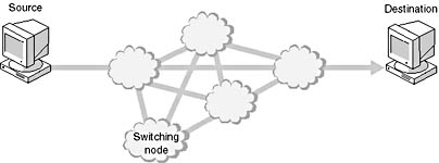
Figure 7.24 X.25 packet switching uses the best routing for each transmission
The early X.25 networks used telephone lines to transmit data. This was an unreliable medium that resulted in frequent errors, so X.25 incorporated extensive error checking. As a consequence of all of the error checking and retransmission, X.25 can appear to be slow.
Today's X.25 protocol suite defines the interface between a synchronous packet-mode host or other device and the public data network (PDN) over a dedicated or leased-line circuit. This interface is a data terminal equipment/data communications equipment (DTE/DCE) interface.
Examples of DTEs include:
- A host computer with an X.25 interface.
- A packet assembler/disassembler (PAD) that receives asynchronous characters, entered from a low-speed terminal, and assembles them into packets to be transmitted over the network. The PAD also disassembles packets received from the network so that the data can be delivered as characters to the terminals.
- A gateway between the PDN and a LAN or WAN.
For all three of these DTE examples, the DCE half of the DTE/DCE is the PDN. See Figure 7.25 for examples of DTEs.
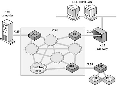
Figure 7.25 Examples of DTEs
Frame Relay
As network communications move toward digital and fiber-optic environments, new technologies are appearing that require less error checking than earlier analog packet-switching methods.
Frame relay is an advanced fast-packet variable-length, digital, packet-switching technology. With this technology, designers have stripped away many X.25 accounting and checking functions that are not necessary in a reliable, secure, fiber-optic circuit environment.
Frame relay, as shown in Figure 7.26, is a point-to-point system that uses a PVC to transmit variable length frames at the data-link layer. The data travels from a network over a digital leased line to a data switch and into the frame-relay network. It passes through the frame-relay network and arrives at the destination network.
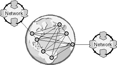
Figure 7.26 Frame relay uses a point-to-point system
Frame-relay networks are popular because they are much faster than other switching systems at performing basic packet-switching operations. This is because frame relay uses PVC so the entire path from end-to-end is known. There is no need for frame-relay devices to perform packet disassembly and reassembly, or to provide best-path routing.
Frame-relay networks can also provide subscribers with bandwidth as needed, which lets the customer make nearly any type of transmission.
Frame-relay technology requires a frame-relay-capable router or bridge to successfully transmit data over the network. A frame-relay router needs at least one WAN port for a connection to the frame-relay network and another port for the LAN.
Asynchronous Transfer Mode (ATM)
Asynchronous transfer mode (ATM) is an advanced implementation of packet switching that provides high-speed data transmission rates to send fixed-size packets over broadband and baseband LANs or WANs. ATM can accommodate:
- Voice.
- Data.
- Fax.
- Real-time video.
- CD-quality audio.
- Imaging.
- Multimegabit data transmission.
The CCITT defined ATM in 1988 as part of the broadband Integrated Services Digital Network (BISDN), discussed later in this lesson. Because of ATM's power and versatility, it is influencing the development of network communications. It is equally adaptable to LAN and WAN environments, and it can transmit data at very high speeds (155 Mbps to 622 Mbps or more).
ATM Technology
ATM is a broadband cell relay method that transmits data in 53-byte cells rather than in variable-length frames. Figure 7.27 illustrates an ATM cell. These cells consist of 48 bytes of application information with five additional bytes of ATM header data. For example, ATM would divide a 1000-byte packet into 21 data frames and put each data frame into a cell. The result is a technology that transmits a consistent, uniform packet.
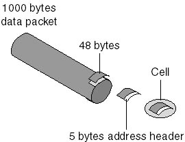
Figure 7.27 ATM cells have 48 bytes of data and a 5-byte header
Network equipment can switch, route, and move uniform-sized frames much more quickly than it can move random-sized frames. The consistent, standard-sized cell uses buffers efficiently and reduces the work required to process incoming data. The uniform cell size also helps in planning application bandwidth.
Theoretically, ATM can offer throughput rates of up to 1.2 gigabits per second. Currently, however, ATM measures its speed against fiber-optic speeds that can reach as high as 622 Mbps. Most commercial ATM boards will transmit data at about 155 Mbps.
As a reference point, at 622 Mbps ATM could transmit the entire contents of the latest edition of the Encyclopedia Britannica, including graphics, in less than one second. If the same transfer were tried using a 2400-baud modem, the operation would take more than two days.
ATM can be used in LANs and WANs at approximately the same speed in each. ATM relies on carriers such as AT&T and Sprint for implementation over a wide area. This creates a consistent environment that does away with the concept of the slow WAN and the differing technologies used in the LAN and WAN environments.
ATM Components
ATM components are currently available through only a limited number of vendors. All hardware in an ATM network must be ATM-compatible. Implementing ATM in an existing facility will require extensive equipment replacement. This is one reason why ATM has not been adopted more quickly.
However, as the ATM market matures, various vendors will be able to provide:
- Routers and switches to connect carrier services on a global basis.
- Backbone devices to connect all the LANs within a large organization.
- Switches and adapters that link desktop computers to high-speed ATM connections for running multimedia applications.
ATM Media ATM does not restrict itself to any particular media type. It can be used with existing media designed for other communications systems including:
- Coaxial cable.
- Twisted-pair cable.
- Fiber-optic cable.
However, these traditional network media in their present forms do not support all of ATM's capabilities. An organization called the ATM Forum recommends the following physical interfaces for ATM:
- FDDI (100 Mbps)
- Fiber Channel (155 Mbps)
- OC3 SONET (155 Mbps)
- T3 (45 Mbps)
Other interfaces include frame relay and X.25, discussed earlier in this lesson.
ATM Switches ATM switches are multiport devices that can act as either of the following:
- Hubs to forward data from one computer to another within a network
- Router-like devices to forward data at high speeds to remote networks
In some network architectures, such as Ethernet and Token Ring, only one computer at a time can transmit. In Figure 7.28, three routers are feeding data into the ATM switch and onto the ATM network at the same time.
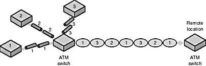
Figure 7.28 ATM switches act as multiplexers allowing multiple data input
ATM Considerations
ATM technology requires special hardware and exceptional bandwidth to reach its potential. Applications that support video or voice would overwhelm most older network environments and frustrate users trying to use the network for normal business. Also, implementing and supporting ATM requires expertise that is not widely available.
Integrated Services Digital Network (ISDN)
Integrated Services Digital Network (ISDN) is an inter-LAN digital connectivity specification that accommodates voice, data, and imaging. One of the original goals of ISDN developers was to link homes and businesses over copper telephone wires. The early ISDN implementation plan called for converting existing telephone circuits from analog to digital. This plan is being implemented worldwide.
Basic Rate ISDN divides its available bandwidth into three data channels. Two of these move data at 64 Kbps, while the third transmits at 16 Kbps.
The 64 Kbps channels are known as B channels. These can carry voice, data, or images. The slower 16 Kbps channel is called the D channel. The D channel carries signaling and link management data. ISDN Basic Rate desktop service is called 2B+D.
A computer connected to an ISDN service can use both B channels together for a combined 128 Kbps data stream. If both end stations also support compression, much higher throughput can be achieved.
Primary Rate ISDN uses the entire bandwidth of a T1 link by providing 23 B channels at 64 Kbps and one D channel at 64 Kbps. The D channel is used only for signaling and link management.
Networks that plan to use ISDN services should consider whether to use Basic Rate or Primary Rate, based on their need for data throughput. ISDN is the digital replacement for PSTN and, as such, is a dial-up service only. It is not designed to be a 24-hour (like T1) or bandwidth-on-demand (like frame relay) service.
Fiber Distributed Data Interface (FDDI)
Fiber Distributed Data Interface (FDDI) is a specification that describes a high-speed (100 Mbps) token-ring network that uses fiber-optic media. It was produced by the X3T9.5 committee of the American National Standards Institute (ANSI) and released in 1986. FDDI was designed for use with high-end computers that required greater bandwidth than the 10 Mbps Ethernet or 4 Mbps of existing Token Ring architectures.
FDDI is used to provide high-speed connections for various types of networks. FDDI can be used for metropolitan area networks (MANs) to connect networks in the same city with a high-speed fiber-optic cable connection. It is limited to a maximum ring length of 100 kilometers (62 miles), so FDDI is not really designed to be used as a WAN technology.
Networks in high-end environments use FDDI to connect components, such as large and small minicomputers, in a traditional computer room. These are sometimes called "back-end networks." These networks typically handle file transfer far more than interactive communication. When communicating with a mainframe, minicomputers or personal computers often require constant, real-time use of the media. They might even need exclusive use of the media for extended periods of time.
FDDI works with backbone networks to which other low-capacity LANs can connect. It is not wise to connect all the data-processing equipment in a company to a single LAN because the traffic can overload the network, and a failure can halt the company's entire data-processing operation.
LANs that require high data rates and fairly extensive bandwidth can use FDDI connections. These are networks composed of engineering computers or other computers that must support high-bandwidth applications such as video, computer-aided design (CAD), and computer-aided manufacturing (CAM).
Any office requiring high-speed network operations might consider using FDDI. Even in business offices, the need to produce graphics for presentations and other documentation can saturate and slow a network.
Token Passing
While FDDI uses a standard token-passing system, there are differences between FDDI and 802.5. A computer on an FDDI network can transmit as many frames as it can produce within a predetermined time before letting the token go. As soon as a computer has finished transmitting, it releases the token.
Because a computer releases the token when it has finished transmitting, there can be several frames circulating on the ring at once. This explains why FDDI offers higher throughput than a Token Ring network, which allows only one frame at a time to circulate.
Topology
FDDI operates at 100 Mbps over a dual-ring topology that supports 500 computers over a distance of up to 100 kilometers (62 miles).
FDDI uses shared network technology. This means that more than one computer at a time can transmit. Although FDDI can provide 100 Mbps service, the shared network approach can still become saturated. For example, if 10 computers all transmit at 10 Mbps, the total transmission will equal 100 Mbps. In transmitting video or multimedia, even the 100 Mbps transmit rate can become a bottleneck.
As shown in Figure 7.29, FDDI uses the token-passing system in a dual-ring setting. Traffic in an FDDI network consists of two similar streams flowing in opposite directions around two counter-rotating rings. One ring is called the "primary ring" and the other is called the "secondary ring."
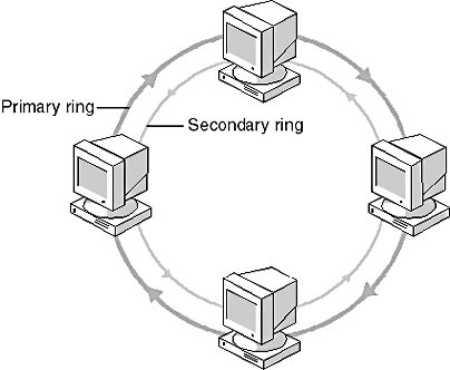
Figure 7.29 FDDI uses a dual-ring topology
Traffic usually flows only on the primary ring. If the primary ring fails, FDDI automatically reconfigures the network so that the data flows onto the secondary ring in the opposite direction.
One of the advantages of the dual-ring topology is redundancy. One of the rings is used for transmission, and the other is used for backup. If there is a problem, such as a ring failure or a cable break, the ring reconfigures itself and continues transmitting.
The total cable length of both rings combined must not exceed 200 kilometers (124 miles), and it cannot hold more than 1000 computers. However, because the second, redundant ring protects against ring failure, the total capacities should be divided in half. Therefore, each FDDI network should be limited to 500 computers and 100 kilometers (62 miles) of cable. Also, there must be a repeater every two kilometers (1.24 miles) or less.
Computers may connect to one or both FDDI cables in a ring. As shown in Figure 7.30, those that connect with both cables are known as Class A stations, and those that connect to only one ring are called Class B stations.
If there is a network failure, Class A stations can help reconfigure the network; Class B stations cannot.
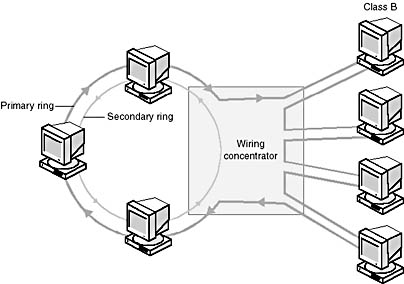
Figure 7.30 Class A computers connect to both rings; Class B computers connect to only one
FDDI in a Star FDDI computers can accommodate point-to-point links to a hub. This means that FDDI can be implemented using the star-ring topology. This is an advantage in that it can:
- Help in troubleshooting.
- Take advantage of the management and troubleshooting capabilities of advanced hubs.
Beaconing
All computers in an FDDI network are responsible for monitoring the token-passing process. To isolate serious failures in the ring, FDDI uses a system called beaconing. With beaconing, the computer that detects a fault sends a signal, called a "beacon," onto the network. The computer continues to send the beacon until it notices a beacon from its upstream neighbor, and then it stops sending. This process continues until the only computer sending a beacon is the one directly downstream of the failure.
As illustrated in Figure 7.31, Computer 1 faults. Computer 3 detects the fault, starts to beacon, and continues to do so until it receives a beacon from Computer 2. Computer 2 continues to beacon until it receives a beacon from Computer 1. Because Computer 1 is the one with the fault, Computer 2 will continue to beacon and pinpoint the fault's location on Computer 1.
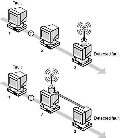
Figure 7.31 FDDI uses beaconing to isolate problems
When the beaconing computer finally receives its own beacon, it assumes the problem has been fixed and regenerates a token; then the network returns to normal operation.
Media
FDDI's primary medium is fiber-optic cable. This means that FDDI is:
- Immune to electromagnetic interference or noise.
- Secure, because fiber-optic cable does not emit a signal that can be monitored, and it cannot be tapped.
- Able to transmit long distances before needing a repeater.
FDDI can also be used on copper wire, known as copper-distributed data interface (CDDI), but this will seriously limit its distance capabilities.
Synchronous Optical Network (SONET)
Synchronous optical network (SONET) is one of several emerging systems that take advantage of fiber-optic technology. It can transmit data at more than one gigabit per second (Gbps). Networks based on this technology are capable of delivering voice, data, and video communication.
SONET is a standard for optical transport that was formulated by the Exchange Carriers Standards Association (ECSA) for ANSI. SONET has also been incorporated into the Synchronous Digital Hierarchy recommendations of the CCITT, also known as the International Telecommunications Union (ITU), which sets the standards for international telecommunications.
SONET defines optical-carrier (OC) levels and electrical-equivalent synchronous transport signals (STSs) for the fiber optic-based transmission hierarchy.
SONET uses a basic transmission rate of STS-1, which is equivalent to 51.84 Mbps. However, higher-level signals are achievable and are integer multiples of the base rate. For example, STS-3 is three times the rate of STS-1 (3 X 51.84 = 155.52 Mbps). An STS-12 would be a rate of 12 x 51.84 = 622.08 Mbps.
SONET provides sufficient payload flexibility that it can be used as the underlying transport layer for BISDN ATM cells. BISDN is a single ISDN network that can handle voice, data, and video services. ATM is the CCITT standard that supports cell-based voice, data, video, and multimedia communication in a public network under BISDN. The ATM Forum is aligning with SONET as the transport layer for cell-based traffic.
Switched Multimegabit Data Service (SMDS)
Switched Multimegabit Data Service (SMDS) is a switching service provided by some local exchange carrier services. Transmission speeds range from 1 Mbps to 34 Mbps with many-to-many connectivity. Unlike a dedicated mesh network (a network with multiple active paths), this connectionless service offers high bandwidth at reduced network costs.
SMDS uses the same fixed-length cell relay technology as ATM. One SMDS line with the appropriate bandwidth connects into the local carrier and can provide connections between all sites without a call setup or teardown procedure. SMDS does not perform error checking or flow control; that is left up to the sites being connected.
SMDS is compatible with the IEEE 802.6 MAN standard as well as with BISDN, but SMDS provides management and billing services not specified in the IEEE 802.6 specification.
SMDS uses the distributed queue dual bus (DQDB) as the interface and access method for the network. SMDS is a dual-bus topology that forms a ring that is not closed.
Lesson Summary
The following points summarize the main elements of this lesson:
- Two types of telephone lines are available for modem communications: public telephone lines (dial-up lines) and leased lines (dedicated lines).
- Most long-distance carriers use switched circuits to provide what appear to be dedicated lines, also called virtual private networks (VPNs).
- To make a Remote Access Service (RAS) connection, the server on the network must be configured with RAS, and the computer connecting to the network must be configured as a client or with dial-up networking (DUN).
- RAS connections can use any one of three protocols: Serial Line Interface Protocol (SLIP), Point-to-Point Protocol (PPP), or Point-to-Point Tunneling Protocol (PPTP).
- RAS provides four levels of security: auditing, callback, security host, and PPTP filters.
- The Point-to-Point Tunneling Protocol (PPTP) allows a remote client to make a secure connection to a network over the Internet.
- Organizations that need a more secure and faster connection than can be provided by an analog line will convert to DDS (digital data service).
- T1 service is the most widely used kind of digital line.
- Packet-switching networks offer a fast and efficient way to transit data over wide areas.
- Frame relay is an advanced fast-packet variable-length, digital, packet-switching technology.
- Asynchronous Transfer Mode (ATM) is an advanced implementation of packet switching that provides high-speed transmission rates to send fixed-size packets over broadband and baseband LANs and WANs.
- Integrated Services Digital Network (ISDN) is an inter-LAN digital connectivity specification that accommodates voice, data, and imaging.
- Fiber Distributed Data Interface (FDDI) is a specification that describes a high-speed token-passing network that uses fiber-optic media.
- Synchronous Optical Network (SONET) is an emerging technology based on fiber optics.
- Switched Multimegabit Data Service (SMDS) is a connectionless switching service provided by local exchange carrier services that offers high bandwidth at reduced network costs.

Exercise 7.1: Troubleshooting Problem
Use the information below to help you solve the troubleshooting problem that follows.
Background Information
One of the key resources for troubleshooting communications problems is the vendor who manufactured the product. Most system administrators do not have extensive knowledge of telecommunications technology, while telecommunications vendors typically have staff members who have this type of expertise. Often, however, actual problems are not nearly as difficult to resolve as they first appear to be. Consider the following example:
A medium-sized computer firm lost its telephone service every Monday morning for nearly six months. Each Monday, employees would arrive at work to find that the telephone system was not working. Because no one in the company had the expertise to solve the problem, they contacted their telephone vendor, who sent someone out to repair the system. The telephone company sent a different technician each time, and each time it took the technician only about 15 minutes to fix the system.
One Monday, one of the computer firm's own technicians went to watch the telephone vendor's technician bring the system back up. The technician simply located the telephone system's surge suppressor and hit the reset switch. That was the total fix, and anyone who knew how to reset the surge suppressor (simply by pressing a reset button) could now repair the telephone system.
The point of this story is that even in a complex environment, problems and their solutions do not necessarily have to be complex.
While the answer was ultimately simple, the telephone company's technician was the only person who had the initial expertise necessary to locate and eliminate the problem. If you have WAN communication problems and you have eliminated the LAN's local components as a source of trouble, do not hesitate to call the service provider to ask for help. While this can result in an initial expense, time and money will be saved in the long run.
With that story in mind, forge ahead and work through the following troubleshooting problem.
The Problem
You are the multitalented network administrator and technician for this computer firm. Your LAN is connected to another LAN in a city 806 kilometers (500 miles) away. The communication link is a digital T1 with a multiplexer that allows you to send telephone conversations and data simultaneously on the same link.
When you came into work on Monday morning, you immediately began to hear complaints from employees who could not use the WAN to access resources at the other site. After some checking, you discovered that you can use the T1 for telephone conversations, but you cannot send or receive data over the link. You now examine all the equipment and connectors but cannot see any obvious loose or frayed connections, and all of the equipment appears to be plugged in and turned on.
What can you do to start the troubleshooting process?
Answers
Exercise 7.2: Case Study Problem
A magazine publisher based in Seattle has two branch offices: one in Fort Lauderdale, Florida, and one in New York City. Each office is internally and separately networked. The networks were implemented five years ago, and each has a coaxial linear-bus topology supporting Ethernet 10 Mbps traffic. The branch offices stay in touch with each other by telephone and Federal Express.
Recently, the company has begun to develop projects that involve team members from more than one office. Each office has resources that the other two do not; the current projects require all of these resources. The internal networks have had frequent cable problems, and each time they have a problem, the entire office network goes down until the problem is resolved.
The management team would like a network design that offers easier troubleshooting, less down time, and provides WAN communication between sites. They would like the WAN connection to be able to support about 256 Kbps of data and several analog telephone conversations between sites (the long-distance bills have been unacceptably high). The combination of long-distance and Federal Express charges should be eliminated by the WAN. Management would like the WAN to be able to continue operating even if one of the WAN links should fail.
- Identify at least two network items in each branch-office network site that need upgrading.
- The separate branch offices need to maintain voice and data communications with each other. Which type of WAN connection (link) might you use to connect the three sites to each other?
- Which type of device could be used to collect the multiple signals from voice and data and put them on the same WAN link?
- Which type of connectivity device should be used to connect the LAN to the multiple paths in the WAN illustrated in the diagram above?
Answers
Exercise 7.3: Network Planning Problem
Answering the following questions will help you determine which, if any, WAN or advanced transmission components you should consider for your network needs.
Modems
- Do you need to communicate with bulletin board services (BBSs) and information service providers such as the Microsoft Network, America Online, or CompuServe?
- Do you need individual connectivity to the Internet?
- Do you need to transfer files periodically with another user at a different location?
- Will several users at once need to communicate occasionally with an online service or any remote resource?
- Do your users periodically need to access the network from home or on the road?
Yes ____
No ____
Yes ____
No ____
Yes ____
No ____
If the answers to any of the first three questions was yes, you need a modem. Your next step is to research which vendor's modem best fits your needs.
Yes ____
No ____
If the answer is yes, you should consider a modem pool.
Yes ____
No ____
If the answer is yes, you might need remote access service. To implement this, you will also need a remote access server.
Creating Larger Networks
You should consider adding WAN connectivity devices to your network if it is getting too large and difficult to manage. Difficulties could result from the addition of an unanticipated number of users, or where existing users have acquired new applications that generate greater network traffic than the original network was designed to accommodate. You might also need to connect multiple sites or multiple networks.
The determining factors in choosing a WAN connection service include:
- Which services are available in your area.
- What kinds of services you need.
The following questions will help you identify which connectivity devices would be appropriate for your system.
Repeaters
- Do you need to extend the cable length of your network to accommodate new users located farther from the server?
- If you extend the length of your network cable, will the newly extended cable length exceed the specifications for that type of cable?
- Do you need to transmit signals on different media than that which you are already using for your network? (For example, do you need to connect a thinnet segment to an Ethernet 10BaseT network?)
Yes ____
No ____
Yes ____
No ____
Yes ____
No ____
If the answer to any of the above questions is yes, you should consider using a repeater to expand your network.
Bridges
NOTE
A rule of thumb among many experienced network professionals is to use a bridge when dealing with nonroutable protocols. Otherwise, use a router.
- Do you need to connect two or more network segments?
- Do you need to connect two networks with different network architectures (such as Ethernet to Token Ring)?
- Is your network performance slower than you would like it to be?
- Does your network serve different departments that usually transmit network traffic only within their own department?
Yes ____
No ____
Yes ____
No ____
Yes ____
No ____
If the answer is yes, keep that in mind while you answer the next question.
Yes ____
No ____
If you answered yes to any of the questions, consider using bridges either to segment a single network or to join two different networks.
Routers
NOTE
Many network professionals prefer to use routers when it is possible to use either a bridge or a router to solve the problem. Their general rule is to use a bridge only with nonroutable protocols. In other cases, they use a router. The cost difference between a bridge and a router is small when weighed against the additional capabilities of a router.
- Do you need to join several LAN segments into a single network?
- Do you need to connect different network architectures (such as Ethernet to Token Ring)?
- Do you need to isolate or filter traffic between multiple segments?
- Are network performance and data integrity important enough to maintain redundant paths between multiple segments simultaneously?
- If you have multiple paths available, do you want to route packets on a "best path" algorithm?
Yes ____
No ____
Yes ____
No ____
Yes ____
No ____
Yes ____
No ____
Yes ____
No ____
If the answer to any of these questions is yes, you should consider implementing routers between the different segments.
Gateways
- Do you need to allow communication between unlike systems? (For example, do any users need to access a mainframe computer? Do users of Microsoft network software need to access servers running network software from Novell? Do users of network software from Novell need to access files on a computer running UNIX?)
Yes ____
No ____
If your answer is yes, you should consider a gateway.
Choosing Advanced WAN Transmission Technologies
Choosing a WAN connection service varies from location to location based on available services and your network needs. You will need to do some market research to determine which service provider can best meet your system needs. The following questions can help you identify some of the services you will need.
- Do you have only two sites to link?
- Does your system need to link multiple sites to a central location?
- Does your system need to link many sites simultaneously?
- Is the data that you transmit so critical to protect that you require multiple links between sites to provide redundancy in case of link failure?
Yes ____
No ____
If the answer is yes, you probably need point-to-point service.
Yes ____
No ____
If the answer is yes, you probably need a point-to-multipoint service.
Yes ____
No ____
If the answer is yes, you probably need a multipoint-to-multipoint service.
Yes ____
No ____
If the answer is yes, you might need multiple links.
NOTE
Frame relay and other switching technologies provide redundancy, but not at the transmitting or receiving site. Also, because service providers bill for packet switching by the packet, switching technology can be either more or less expensive than T1, depending on the type of data and frequency of transmission. The service provider is the best source of information about costs.
- Which kind of network traffic will be on the link? (Check all that apply.)
- Voice ____
- E-mail ____
- Light file transfer ____
- Heavy file transfer ____
- Client/server database activity (likely to be fairly light network traffic) ____
- Client-computer database activity with the data files stored on a remote server (can be very heavy traffic) ____
- Based on the amount of network traffic identified in the previous question, approximately how much network bandwidth do you need? (Your WAN vendor might be able to help you determine this.)
- Less than 56 Kbps ____
- 56 to 64 Kbps ____
- 128 Kbps ____
- 256 Kbps ____
- 1 Mbps ____
- More than 1 Mbps ____
- Which types and speeds of WAN connection services (service providers) are available in your area?
NOTE
You will need to do some homework and research service providers to answer this.
- Which of the above services can meet your requirements as determined by your answers to questions 1 to 3?
- Which service that can meet your requirements provides the best price and performance for your WAN needs?
Exercise Summary
Put a check mark next to the component you will need, indicate how many components you will need, and note the parameters. To do this, it can help to draw a map of the network and place the components on the map.
NOTE
Before filling out this chart, you will need to research different vendors and products to identify those that best fit your system's needs.
Components
| Component | Number | Notes and parameters |
|---|---|---|
| Modem | ||
| Repeater | ||
| Bridge | ||
| Router | ||
| Gateway |
Service Providers
| Service | Provider | Cost/notes |
|---|---|---|
| 1. Point-to-point | ||
| 2. Point-to-multipoint | ||
| 3. Multipoint-to-multipoint | ||
| 4. T1 | ||
| 5. Multiple T1 |
EAN: 2147483647
Pages: 106