7.2 Physical Media
| There are essentially two possibilities for the medium of a modern network: unshielded twisted-pair (UTP) or fiber optic cables. Fiber, in general, allows for higher data rates over longer distances and is substantially more secure, but is significantly more expensive. [4] There are three problems associated with transmitting data over a physical distance: attenuation, distortion, and interference.
Attenuation occurs because it requires some amount of signal energy to "push" past the resistance of the wire. This results in a gradual degradation of the signal, because it is losing energy to the wire as it proceeds down the line. Distortion is a function of the way that signals travel through a medium: different frequencies are impeded in diferent ways, muddying the signal. Finally, interference occurs because of outside factors that introduce noise into the signal. 7.2.1 UTPUnshielded twisted-pair cable is divided into several categories based on the characteristics of the cable. Higher categories are able to resist noise at higher frequencies, and therefore are more likely to resist external interference. The UTP category classifications are summarized in Table 7-1. Table 7-1. UTP categories
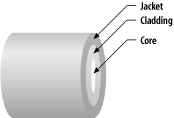
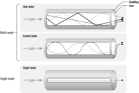
There is a new, emerging cable standard, called Category 5E or Category 6. This cable relies on a special stiffening core in order to maintain the twist in the signaling lines. This standard has specific utility in very high-bandwidth applications (such as Gigabit Ethernet over copper media). There are two types of connectors commonly used with UTP cabling: RJ-11 and RJ-45. RJ-11 is the standard four-pin connector used in telephone jacks , which is rarely found in modern network installations. RJ-45 actually defines a specific pin-out, but the term is commonly used to describe the standard eight-pin connector used almost universally in networking. 7.2.1.1 A note on terminology: plugs and jacksA plug is the male connector on the end of a cable; a jack is the female connector in a patch panel or wall plate. When you are looking at a jack in a wall, with the clip facing down, pin 1 is leftmost. When you are looking "down" a cable with the clip on the plug facing down, pin 1 is rightmost. 7.2.2 FiberFiberoptic cable consists of three parts : a glass or plastic core through which light propagates, surrounded by a cladding , which is also made of glass or plastic but has substantially different optical properties. The core and cladding are both surrounded by a jacket , which provides protection from environmental compromise. Light from a source enters the core: rays that enter at a shallow angle (almost straight down the core) are reflected by the cladding and propagate down the core, whereas rays that enter with a large angle are absorbed by the outer layers . A ray that enters the fiber is called a mode . It is for this reason that fiber is very sensitive to bend radius in the cable; if you bend a piece of cable in too tight of a loop, you will lose some of the transported light. This results in a phenomenon known as attenuation , and while it doesn't cause signal loss, it does reduce range. Figure 7-1 shows a cross-section of a fiberoptic cable. Figure 7-1. A fiberoptic cable in cross-section This type of propagation is called multimode (often abbreviated MMF, for multimode fiber), because there are many possible modes that can be sent through the fiber at once, and propagate through at differing rates. Multimode fiber generally has a core size of 50 or 62.5 microns. The light rays proceed through the fiber along different paths, which causes different rays to arrive at the receiving end of the fiber at different times. A smearing effect occurs that is proportional to distance. Eventually, the pulses are distorted enough to cause data integrity problems. This effect is tolerated because of the low cost of multimode fiber. There are two varieties of multimode fiber: step-index and graded-index fiber. In step-index fiber, the refractive indices of the core and the cladding differ , but the refractive index is the same throughout the core. The result is a dispersion pattern like that described, where the lengths of the paths of light increase with distance. In graded-index fiber, the refractive index of the core varies across the cross section, reducing the difference in path lengths and correspondingly increasing the usable distance. Single-mode fiber, or SMF, has a very narrow core, generally from two to ten microns. This means that only a single mode can propagate along the axis, which completely solves the internal reflection problems with multimode fiber. Single-mode fiber has a very high range (kilometers). Figure 7-2 illustrates multimode step-index, graded-index, and single-mode fiber. Figure 7-2. Multimode step-index, graded index fiber, and single-mode fiber There are many different common forms of connectors used in fiber installations, but there are three particularly common ones. FSD, or Fixed Shroud Device , is typically used in FDDI. ST is a common bayonet-style connector that uses one connector per strand . SC is the international standard: it is a clip-type connector that has the advantage over ST of being a single connector containing both the transmit and receive fibers. The common mnemonic for remembering which of these connectors is which is "stab-twist and stab-click." There have been recent pushes to create a new connector standard, of which the most likely contender is LC, which was designed at Lucent Technologies. |