 |  | | | Chapter 3 - Diagramming Business Objects | | | byAndrew Filevet al.? | | | Wrox Press ©2002 | | | | | Now that we have a basic idea of our data structure (and are agreeable to changing it as further analysis and design dictates), we're ready to create business object classes implementing the functionality of our "Check Out Media" use case. The main tool for achieving this is the sequence diagram. You can create a sequence diagram for each use case in your model, allowing you to model the behavior and collaboration between business objects in your application. Creating a sequence diagram is a dynamic process that involves the following steps: -
Reading through the steps of your use case. -
Creating business objects that carry out the use case. -
Adding business objects to the sequence diagram, and deciding which objects should carry out each responsibility. -
Adding messages between objects on the diagram. A message sent to an object in a sequence diagram creates a new operation on the receiving object. To create a new sequence diagram, right-click the Top Package node in the Model Explorer and select New | Sequence Diagram from the shortcut menu. This opens a new, empty sequence diagram in Visio and adds a node named Sequence-1 to the Model Explorer. Right-click this node, select Rename from the shortcut menu, and change the name to Check Out Media. Changing the Drawing Page Orientation By default, the sequence diagrams drawing page orientation is the same as your printer paper orientation (either landscape or portrait). I prefer to use landscape orientation for my sequence diagrams to give myself a little breathing room on the horizontal axis. If you want to do this, select File | Page Setup... from the menu, which launches the Page Setup dialog as shown in the following image: 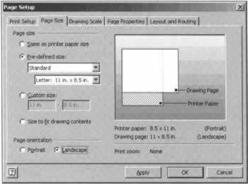 Select the Page Size tab, and under Page size select the Pre-defined size option. Then, under Page orientation, select Landscape. If your printer paper orientation is set to portrait, this will be shown in the image to the right of the Page Size tab. When you're done, click OK to save changes and close the Page Setup dialog. Adding Use Case Text to the Sequence Diagram First of all, enter the explanation of the use into the Documentation box; the explanation is the numbered list on page 105, also listed below: -
The Librarian enters the Borrower's ID. This is either entered manually or scanned from a library card. -
The system responds by displaying the borrower's account. The Display Borrower Account use case is implemented here. Here is the description for this use case: The system displays the borrower's account. This information includes the number of items they can borrow, unpaid fines, and a list of media checked out. The "checked out media" list includes due date and special indication for overdue media. Here are the business rules for checking out media: the Borrower can only check out items if they have no overdue media, less than five articles checked out, and outstanding fines less than fifty dollars. -
The Librarian enters the media ID. This is either entered manually or scanned from the media bar code. -
The system responds by marking the media as "checked out". This step can be repeated for the total number of items a borrower can check out. Before we get into the meat of the sequence diagram, let's first add some initial basic elements. I often find it helpful to add a description of the use case I'm modeling to the sequence diagram. Although this is a bit unconventional, it doesn't break the rules of the UML, but it provides a great reference when creating a sequence diagram and later understanding it. -
Double-click the Check Out Media use case node in the Model Explorer, which launches the UML Use Case Properties dialog as shown in the following image. Select all the text in the Documentation box and press Ctrl+C to copy it to the clipboard. Press Cancel to close the dialog. 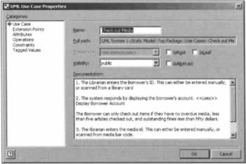 -
Select the sequence diagram by clicking somewhere on its design surface, and then pressing Ctrl+V to paste the text onto the diagram. -
Change the font size of the text block (I usually set it to 10 points), and then resize the textbox so it forms a tall, thin rectangle on the right side of the diagram as shown in the following image. 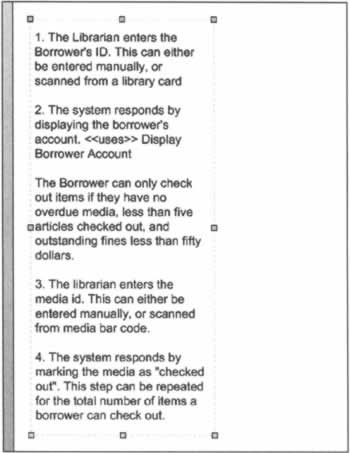 Adding the Actor and UI Placeholder The next step in creating our sequence diagram is adding the actor to the diagram and a user interface placeholder class. Adding these elements to a sequence diagram gives your sequence diagram context. It allows you to show how the user interacts with the computer system, and how the business objects within your application respond. Since we didn't build the use case diagram in this chapter, we need to create a Librarian actor we can use in our sequence diagram. To do this, follow these steps: -
First add a Use Case package to contain the new Librarian actor by right-clicking the Top Package node, and selecting New | Package from the context menu. -
In the UML Package Properties dialog, enter Use Cases in the Name text box, and then click OK to save changes. -
Right-click the new Use Cases package and select New | Actor from the context menu, which launches the UML Actor Properties dialog as shown in the following image. 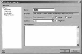 -
In the Name text box, enter Librarian, and then click OK to save changes and close the dialog. When you're finished, you should see the new Librarian actor in the Model Explorer as shown in the following image. 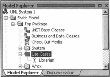 Next, follow these steps to add the Librarian actor to the diagram: -
Make sure the UML Sequence stencil is selected as shown in the following image: 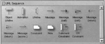 -
Drag an Object Lifeline shape from the stencil and drop it on the top of sequence diagram to the immediate right of the use case text. This displays a shape named Object1 with a lifeline beneath it as shown in the following image.  -
Right-click Object1 and select Properties from the shortcut menu, which launches the UML Classifier Role Properties dialog shown in the following image. 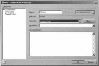 -
In the Classifier combo box, select Use Case::Librarian, and then click OK. This displays the Librarian actor shape on the diagram. -
By default, the Librarian actor shape displays the object name (Object1) rather than the name of the class. Let's change the shape and diagram settings to display the classifier instead. To do this, right-click the Librarian shape and select Shape Display Options... from the shortcut menu. This displays the UML Shape Display Options dialog shown in the following image. 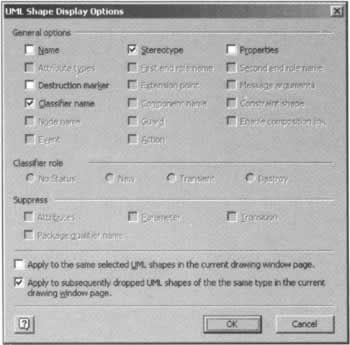 -
Clear the Name checkbox and select the Classifier name checkbox instead. Also select the Apply to subsequently dropped UML shapes of the same type in the current drawing window page checkbox. This ensures all shapes we drop on the diagram from this point on also use these settings. Click OK to close this dialog. When you're done, the Librarian actor shape should look like the following image: 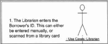 Next, we need some way to represent the user interface on our sequence diagram. In a simple system, the easiest way to do this is to create a single class that represents our application's user interface. This class acts as a placeholder for all user interface elements in our application. We can add this user interface placeholder class to our diagram and send messages to it from the actor that represent actions the user takes when interacting with the user interface. If your application is more complex and has many forms, you might want to create create a different concrete user interface class for each form. This is a simple model, so we'll just create one class named UI to represent the entire user interface. -
Right-click the Top Package node in the Model Explorer and select New | Class from the shortcut menu. In the UML Class Properties dialog, set the Name to UI and enter the following description in the Documentation box: User interface placeholder. -
Click OK to save changes and close the dialog. -
Drag another Object Lifeline shape from the UML Sequence stencil and drop it on the sequence diagram to the immediate right of the Librarian actor shape. Double-click the shape, and in the UML Classifier Role Properties dialog's Classifier combo box, select Top Package::UI. -
Click OK to save changes and close the dialog. When you're done, the sequence diagram should look like the following image - adding both an actor and user interface placeholder to your sequence diagrams provides a context for understanding your application's business object interaction. It allows you to see how specific business objects respond to a user's interaction with the computer system. 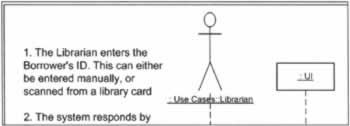 Adding Messages Between Objects Now we're ready to add our first message between objects. Although this isn't a true message because our UI placeholder isn't a real class, this will give you a feel for how it's done. -
Lengthen the object lifelines beneath the Librarian and UI objects. To do this, click on the lifeline and then drag the yellow diamond at the end of the lifeline towards the bottom of the diagram. -
Drag an Activation shape from the UML Sequence stencil onto the lifeline a little below the Librarian shape as shown in the following image. You may need to move the Activation shape up or down slightly to properly glue it to the object lifeline. You'll know it's properly connected when the shape turns from red to black. You can also see any semantic errors and warnings listed in Visio's Output window. Also, notice we've left some space between the bottom of the Librarian description and the top of the Activation shape. This provides room for the message text, which we'll be adding soon. 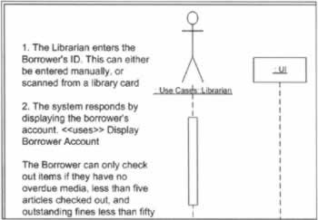 -
Drag another Activation shape from the UML Sequence stencil and drop it on the UI object's lifeline. Make sure the activation box tops line up on the horizontal axis. You may need to move the UI shape up or down a little to make this happen. You can move the UI object by clicking on it and then pressing the up and down arrow keys. Again, the Activation shape is not properly glued to the lifeline until its border turns black. -
Drag a Message (call) shape from the UML Sequence stencil onto the diagram, (the one with the straight, solid message line and solid arrow head) as shown in the following image. 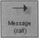 Connect the end of the message without the arrow to the top of the Librarian's Activation shape. Then connect the end of the message with the arrow to the top of the UI object's Activation shape. You'll know it's properly connected when the message arrow turns from red to black. When you're done, your diagram should look like the following image: 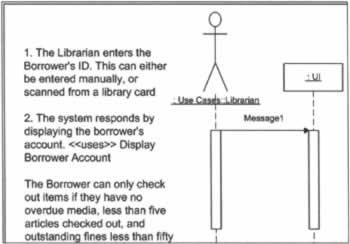 -
Now we're ready to specify the message sent from the Librarian to the user interface. Double-click the message shape. This launches the UML Message Properties dialog, which in turn immediately launches the UML Operation Properties dialog as shown in the following image. 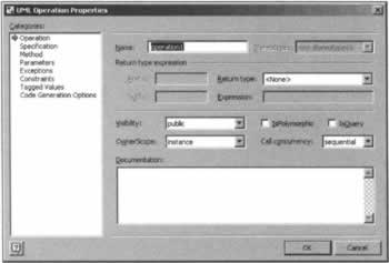 The second dialog is launched because the UI class does not have any operations from which to choose. Any operation you add in the UML Operation Properties dialog is automatically added to the class receiving the message call - in this case, the UI class. -
In the Name text box, type Enter Borrower ID. Because this isn't a real operation (UI isn't a real class, only a placeholder), we can put spaces in the operation name. -
Click OK to close the UML Operation Properties dialog, and then press OK again to close the UML Message Properties dialog. When you're done, your diagrams should look like the following image: 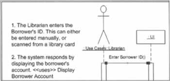 If you're familiar with other UML modeling tools, it may seem odd to manually add Activation shapes to the diagram. At first, I thought this was an unlikable feature of Visio. However, after using it for a while, I came to appreciate its benefits. When I manually add activation shapes to the diagram, I have complete control over their position and size. In tools such as Rational Rose, although the activation boxes are automatically added for me, I usually spend countless hours resizing and moving shapes while Rational Rose is being "overly helpful", auto-sizing and moving shapes where I don't want them! As we've mentioned, when you specify an operation on a message shape, Visio automatically adds the operation to the class of the object receiving the message. If you look at the UI class in the Model Explorer, you'll see it has a new operation named Enter Borrower ID as shown in the following image: 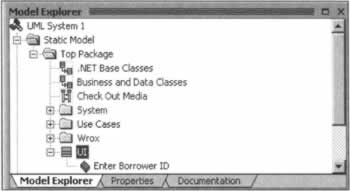 Creating Business Object Classes So far, we've modeled Step 1 of the Check Out Media use case that involves the Librarian entering the Borrower ID. Now, we'll add business objects to the diagram modeling the system's response. The next step in the use case says the system responds by displaying the borrower's account, and then refers us to the Display Borrower Account use case. Here is the full text of this use case: The system displays the borrower's account. This information includes the borrower's name, the number of items they can borrow, unpaid fines, and a list of media checked out. The "checked out media" list includes due date and special indication for overdue media. If we examine our application's data structure, we'll find this information is stored in a few different tables. For example: -
The borrower's name is stored in the Borrower table. -
A list of items they have checked out can be retrieved from the TrxLog table (joined to the Media table for the media description). -
The number of items they can check out is calculated by subtracting the number of items checked out from the total number allowed (five). -
As described in our business rules, borrowers can't check out items if they have more than fifty dollars in outstanding fines. The Fine table contains the information we need to calculate this information. Using our basic rule of thumb of usually creating a business object for each main table in our application, we should create three new business objects to implement this part of the use case: -
Borrower business object -
TrxLog business object -
Fine business object Let's create each of these now - then we'll add them to the diagram as we need them. -
In the Model Explorer, right-click the Top Package | Wrox | UMLDotNet | Business node, and select New | Class from the shortcut menu. -
In the UML Class Properties dialog's Name textbox, enter Borrower. -
In the Documentation box, enter the following: Borrower business object - maintains information regarding people who borrow items from the library. Click OK to close the dialog. -
Add another new class named TrxLog, and specify the following description: Transaction Log business object - maintains information captured each time media is checked in or out. -
Add a third new class named Fine, and specify the following description: Maintains information regarding fines applied to a borrower for overdue media. Next, drag and drop each of these three classes onto the Business and Data Classes class diagram. Afterwards, create a Generalization relationship between each class and the BusinessObject class as shown in the following image: 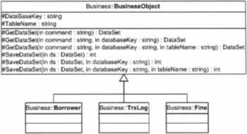 Adding the Borrower Object to the Sequence Diagram Now we're ready to take a closer look at the second step in the use case and assign responsibilities to business objects that carry out the use case. The first thing we'll do is use the Borrower business object to retrieve the borrower's name. To do this, we must send a message from the UI object to the Borrower business object. Follow these steps to add the Borrower class to the diagram and send a message to it: -
Select the "Check Out Media" sequence diagram. -
Drag an Object Lifeline shape from the UML Sequence stencil and drop it onto the sequence diagram, to the immediate right of the UI object. -
Double-click the new shape, and in the UML Classifier Role Properties dialog's Classifier combo box select Business::Borrower. -
Click OK to save changes and close the dialog. -
Resize the Borrower object's lifeline so it's about the same size as the other objects' lifelines. -
Next drag an Activation shape from the UML Sequence stencil and drop it on the Borrower object's lifeline. Place the top of the activation shape a bit lower than the top of the UI object's activation shape as shown in the following image (from this point on, I'll leave out the use case text to save space). 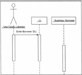 This causes the message passed from the UI object to the Borrower object to be lower in the horizontal plane, indicating the ordering, or sequence of the message. Adding a Message Call to the Borrower Object Now it's time to add a message call from the UI class to the Borrower business object. The Librarian interacts with the user interface by entering the borrower ID. The user interface now makes a call to the Borrower business object which has the responsibility of validating the specified borrower. -
Drag a Message (call) shape from the UML Sequence stencil and drop it onto the sequence diagram. You may find it easiest to attach the arrow end to the top of the Borrower object's activation shape first, and then attach the other end to the UI object's activation shape. -
Double-click the new message to launch the UML Message Properties dialog. The Operation combo box contains a list of all operations defined in the Borrower class and any operations it inherits from base classes. If you open the combo box list, you'll see it contains a list of operations inherited from the BusinessObject class as shown in the following image. 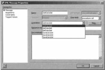 As you can see, it's impossible to tell which overload you are selecting, because the operation signature isn't shown. Microsoft may well address this in a future release of Visio. -
We don't want to use either the GetDataSet or SaveDataSet operation, so click the New button to create a new operation. -
We need to create an operation to retrieve information from the Borrower table for the specified borrower ID. It's best to provide descriptive operation names that are self-documenting. Although you may initially shy away from longer operation names, you'll find being able to figure out what an operation does simply by reading its name is a great time saver. With this in mind, enter GetBorrowerByID in the operation Name textbox. -
In the Return type combo box, select Data::DataSet. -
In the Documentation box, enter the following: Returns a DataSet containing the specified Borrower's information. -
In the Categories pane, select Parameters. Click the New button, and then the Properties... button to launch the UML Parameter Properties dialog. Create a new parameter named borrowerID, and specify its type as string. In this example, we're using a string ID, which may be implemented as a GUID (Globally Unique Identifier). In your applications, you can use any ID type you wish, such as an integer. -
Click OK to close the UML Parameter Properties dialog, click OK again to close the UML Operation Properties dialog, and then click OK once more to close the UML Message Properties dialog. When you're done, the diagram should look like the following image: 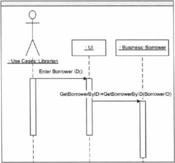 Notice the message text is GetBorrowerByID:=GetBorrowerByID(BorrowerID). The first reference to GetBorrowerByID in this text string indicates that the operation returns a value. This is somewhat unusual for a modeling tool, and I think, undesirable. Although the UML allows you to add return messages to sequence diagrams to indicate a value has been returned from an object, you typically don't need to do so unless something out of the ordinary is returned, because message returns are assumed. Resizing the Activation Shapes In a sequence diagram, the height of an activation box indicates the lifetime of the associated operation. At this point, let's shorten the Borrower.GetBorrowerByID() activation, because the method is called, returns a value, and finishes execution. To do this, select the activation shape and drag the bottom of the shape up as far as Visio allows. We have a few more operations to call from the UI object, so lengthen both the Librarian and UI object activation shapes a bit. When you do this, it may move one or both sides of the Enter Borrower ID message. If this happens, just move the message back to the top of the activation shapes. When you're finished, your diagram should look something like the following image: 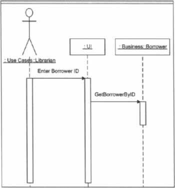 Retrieving Checked-Out Media Next, we need to get a list of media checked out by the current Borrower. The TrxLog object is capable of giving us this information. In addition to this "media checked out" list, our use case also says we need to determine how many items a borrower can check out. There are two main criteria we must check - the number of items already checked out (they can borrow a maximum of five items), and outstanding fines (they can't check out media if they have more than fifty dollars in outstanding fines). We'll have to enlist the help of the Fine business object to calculate these fines. We know we'll need both the TrxLog and Fine objects, so let's add both of these to the diagram now. -
Drag an Object Lifeline from the UML Sequence stencil and drop it on the top of the sequence diagram to the right of the Borrower object. -
Double-click the new object and in the UML Classifier Role Properties dialog, specify the class of the object as Business::TrxLog. -
Click OK to save changes and then lengthen the object's lifeline. -
Drop another Object Lifeline on the diagram to the right of the TrxLog object, and specify the class of the object as Business::Fine. -
Click OK to save changes and then lengthen the object's lifeline. Now we'll add messages to the diagram starting with a message from the UI object to the TrxLog object. We'll also add a call to the Fine object to determine outstanding fines for the specified Borrower. Although we could make individual calls to each object from the UI, we can encapsulate the process by making a single call to the TrxLog object, and have the TrxLog object call the Fine object to determine the amount of outstanding fines. Based on the number of items checked out, and the amount of overdue fines, the TrxLog object can calculate the number of items the Borrower can check out, and return this value in an output parameter. With this solution, the TrxLog and Borrower objects collaborate to fulfill a responsibility. The following steps show how to model this: -
Drag and drop an Activation shape on the TrxLog object's lifeline. Position the top of the activation shape so its top is aligned with the bottom of the GetBorrowerByID() activation shape. -
Drag and drop a Message (call) shape onto the diagram, attaching the arrowhead to the top of the TrxLog object's activation shape and the other end of the message shape to the UI object's activation shape. -
Double-click the new message shape and then click the New button in the UML Message Properties dialog to add a new operation named GetBorrowerCheckedOutMedia. Specify the return type as Data::DataSet, and specify the description as: Returns a DataSet containing all checked out media for the specified Borrower. -
In the Categories pane, select Parameters. Click the New button, and then click the Properties... button to add a new parameter named borrowerID of the type string. -
Add a second parameter named amtCanBorrow. Specify its type as integer, and in the Kind combo box, specify that it is an output parameter (out). In the Documentation box, enter the following: Specifies the number of media the specified borrower can check out. -
Click OK three times to save changes and close all dialogs. When you're finished, your sequence diagram should look like the following image: 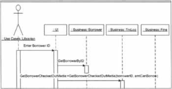 Now we need to add a call to the Fine method from within the TrxLog's GetBorrowerCheckedOutMedia to indicate this method also calculates fines to determine the number of media a Borrower can check out. Calculating Fines As we've mentioned previously, it's a good idea to think about data during object modeling. The following image shows the structure of the TrxLog and Fine tables: 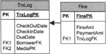 If you look closely at these tables, you'll see there isn't a direct way to get the total outstanding fines for a particular borrower. We could derive this information in a roundabout way by means of the TrxLog table, but because this is something we want to do often, we may want to denormalize the data so this information is more readily available. An easy way to do this is to save both the TrxLog foreign key pointer and a Borrower foreign key pointer in the Fine table. The Borrower key gives us what we need to retrieve outstanding fines for a specific borrower more easily. Assuming this structure, let's finish modeling this part of the sequence diagram Please note that we're still working with our previous sequence diagram. -
Drag an Activation shape from the UML Sequence stencil and drop it on the Fine object's lifeline. Place the top of the Activation shape a few steps lower than the top of the TrxLog's activation shape. -
Drag and drop a Message (call) shape on the sequence diagram. Attach the arrowhead to the top of the Fine object's Activation shape. Attach the other end of the message to the TrxLog object's GetBorrowerCheckedOutMedia activation shape. -
Double-click the new message, and create a new operation named GetBorrowerOutstandingFines. Set the operation Return type to decimal, and in the Documentation box, enter the following: Returns total outstanding fines for the specified Borrower. -
In the Category box, select Parameters. Click the New button, and then click the Properties button to add a single parameter named BorrowerID of type string. -
Click OK three times to save changes and close all dialogs. -
Shorten the Fine object's activation shape to the smallest possible size. Resize the TrxLog object's activation shape so its bottom is aligned with the bottom edge of the Fine object's activation box. When you're finished, your sequence diagram should look like the following image: 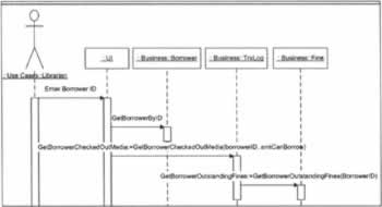 Displaying the Borrower Information Now that we've returned the information we need from the Borrower, TrxLog, and Fine objects, let's add a message to the diagram indicating that this information is displayed to the user interface. The UI object needs to call a method on itself (also known as "local invocation"). Based on this, we're going to use a different message shape than we've used before. -
Drag a "curved" Message (call) shape as shown in the following image from the UML Sequence stencil and drop it on the diagram.  Attach the message shape to the UI object's activation shape. This attaches both ends of the message shape to the activation shape as shown in the following image. 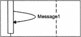 -
Double-click the new message shape, and in the UML Message Properties dialog, click the New button to add a new operation. -
In the UML Operation Properties dialog, set the name of the operation to Display Borrower Account. Remember; because UI is not a 'real' class, we can add spaces in operation names because they will never be implemented in code. -
Click OK to save changes and close both dialogs. When you model a reflexive message call like this, it's best to add an activation shape for the message. This allows you to make calls to other objects from within this message. Although we won't be making any calls from this message, let's add an activation shape to show you how it's done. To add a nested activation shape: -
If necessary, lengthen the UI object's activation shape to make room for the nested activation. -
Drag an Activation shape from the UML Sequence stencil and attach it to the right side of the UI object's activation shape. Place the shape so its top edge touches the point where the message arrowhead meets the original activation shape. -
Resize the new activation shape to the smallest possible size. -
Attach the arrowhead of the Display Borrower Account message to the top right corner of the nested activation shape. When you're finished, your diagram should look like the following image: 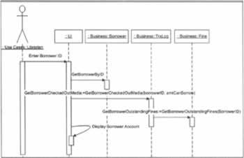 Checking Out Media Now that the borrower's information has been retrieved and displayed, we're ready to model checking out media. If the GetBorrowerCheckedOutMedia operation returned zero (0) in its amtCanBorrow parameter, then the Borrower is unable to check out any media, and the user interface should enforce this. However, assuming the Borrower can check out one or more items, the Librarian interacts with the system again, and we'll use our business objects to respond accordingly. The only business object we need to use when marking media as checked out is the TrxLog object. The Librarian either enters the Media ID by scanning, or manually enters it, and then this Media ID is passed to the TrxLog object, which marks the media as checked out. Here's how we model this: -
Lengthen the lifeline of the Librarian object to accommodate a new activation shape. Increase the size of the UI and TrxLog objects' lifelines to the same length. -
Drag a new Activation shape from the UML Sequence stencil and attach it to the Librarian lifeline beneath the existing activation shape, but leave space between the bottom of the original activation shape and the new activation shape. This provides room for the display of the next message call we will add between the Librarian and the UI object. -
Drag another new Activation shape to the sequence diagram and attach it to the UI object's lifeline. Align the tops of both new activation shapes. -
Drag a new Message (call) shape from the UML Sequence stencil and attach the left side of the message shape to the top of the Librarian's new activation shape. Attach the arrowhead of the message shape to the top of the UI object's new activation shape. -
Double-click the new message shape, and in the UML Message Properties dialog, click the New button to add a new operation. -
In the UML Operation Properties dialog, specify the operation name Enter Media ID. -
Click OK twice to save changes and close both dialogs. When you're finished, your sequence diagram should look like the following image: 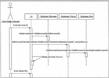 Now we need to add a message from the UI object to the TrxLog object. We'll pass the Borrower ID and Media ID so the TrxLog object knows what media is being checked out and to whom. We'll also pass the current or user-specified date to the TrxLog so it doesn't have to assume the check out date is today's date. -
Drag an Activation shape from the UML Sequence stencil and attach it to the TrxLog object's lifeline. Position the activation shape so its top edge is lower than the Enter Media ID activation shape's top edge. -
Drag and drop a Message (call) shape onto the sequence diagram. Attach the message shape's arrowhead to the top of the TrxLog's new activation shape. Attach the other end of the shape to the UI object's new activation shape. -
Double-click the new message shape and click the New button in the UML Message Properties dialog to add a new operation named CheckOut. Leave the operation's return type as <None>, but in the Documentation box, enter the following: Checks out the media for the specified borrower and date. -
In the Categories pane, select Parameters. Add the following two string parameters to this operation named borrowerID, and mediaID. -
Click OK three times to save changes and close all dialogs. -
Resize the CheckOut message's activation box to the smallest size Visio allows. You can also shorten the Librarian and UI object's activation shapes accordingly. Tweaking the Sequence Diagram After performing the previous steps, resize the CheckOut message's activation box to the smallest size Visio allows. Also, shorten the Librarian and UI object's activation shapes accordingly. Since the Borrower and Fine objects are not involved in the second half of the use case, shorten their lifelines so they line up with the bottom of the Enter Borrower ID activation box. One other adornment we can add to the diagram is destructor shapes. When we're finished using an object, we usually destroy it. You indicate this in a sequence diagram by adding a destructor icon at the bottom of an object's lifeline. To do this, right-click an object's lifeline, and select Shape Display Options... from the context menu. In the UML Shape Display Options dialog shown in the following diagram, just mark the Destruction marker checkbox, click OK to save changes, and close the dialog. 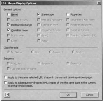 This places a large X at the bottom of the lifeline, as shown in the following image depicting our final sequence diagram: 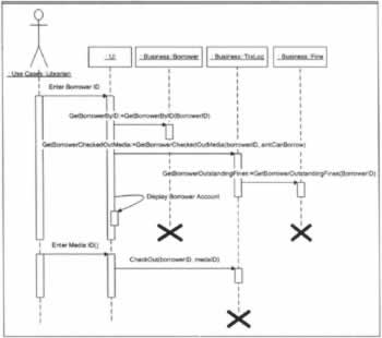 In addition to showing the destruction of an object, you can also model its creation. In our sequence diagram, all business objects are displayed at the very top of the diagram, which does not indicate a specific creation timeframe. If we want to model the creation of an object, we can add a method call that points directly at the object instance. For example, we could model the creation and destruction of the Fine object in our sequence diagram as shown in the following image. 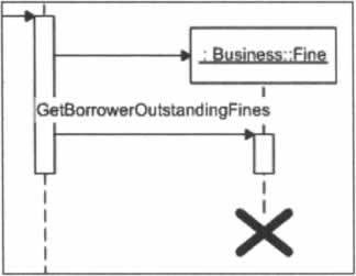 |