Conceptual Underpinnings
| This section provides the foundational knowledge required to understand throughput, topologies, and discovery techniques. ThroughputWhen discussing the throughput of any frame-oriented protocol that operates at OSI Layers 1 and 2, it is important to understand the difference between baud rate, raw bit rate, data bit rate, and upper layer protocol (ULP) throughput rate. The carrier signal is the natural (unmodified) electrical or optical signal. The baud rate is the rate at which the carrier signal is artificially modulated (transformed from one state to another state). Multiple carrier signal transitions can occur between each pair of consecutive artificial state transitions. Baud rate is inherently expressed per second. Bits received from OSI Layer 2 must be encoded into the signal at OSI Layer 1. The number of bits that can be encoded per second is the raw bit rate. The encoding scheme might be able to represent more than one bit per baud, but most schemes represent only one bit per baud. So, the baud rate and the raw bit rate are usually equal. However, the bits encoded often include control bits that were not received from OSI Layer 2. Control bits typically are inserted by the encoding scheme and are used to provide clocking, maintain direct current (DC) balance, facilitate bit error detection, and allow the receiver to achieve byte or word alignment. The number of raw bits per second minus the number of control bits per second yields the data bit rate. This is the number of bits generated at OSI Layer 2 that can be transmitted per second. The data bit rate includes OSI Layer 2 framing bits and payload bits. The ULP throughput rate is the number of payload bits that can be transmitted per second. So, the number of data bits per second minus the number of framing bits per second yields the ULP throughput rate. TopologiesThere are too many design implications associated with each physical topology for this chapter to cover the subject exhaustively. So, this section merely introduces the physical topologies by providing a brief discussion of each. The general points discussed in this section are equally applicable to all networking technologies including the SPI, Ethernet, IP, and Fibre Channel. Note that for any given topology, there might be many names. Each community of network technologists seems to prefer a different name for each topology. Context should be considered when discussing topology. Discussions of very small-scale networks often include the end nodes in the topological context (see the star and linear paragraphs). When discussing medium- and large-scale networks, communication between network devices is the primary topological concern. So, end nodes usually are excluded from that topological context. This section discusses topologies in both contexts. Another important point regarding topology is perspective. Link-state protocols based on the Dijkstra algorithm create a logical tree topology in which each network device sees itself as the root of the tree. By contrast, Ethernet's Spanning Tree algorithm creates a tree topology in which every switch recognizes the same switch as the root of the tree. Perspective partially determines the behavior of a network device in a given topology. Additionally, the physical topology (cabling) and logical topology (communication model) often are not the same. This can cause confusion when discussing certain physical topologies in the context of certain protocols. There are six types of physical topologies:
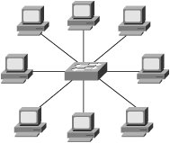
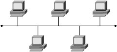
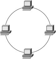
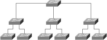
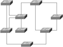
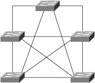
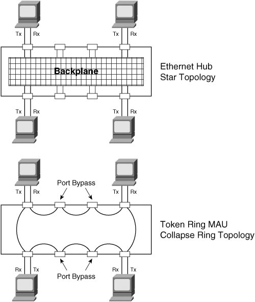
Any of these six physical topologies can be combined to create a hybrid topology. Figures 3-1 through 3-6 illustrate an example of each physical topology. Figure 3-7 illustrates the star topology versus the collapsed ring/loop topology. Figure 3-1. Star/Hub-and-Spoke Topology Figure 3-2. Linear/Bus/Cascade Topology Figure 3-3. Circular/Ring/Loop Topology Figure 3-4. Tree Topology Figure 3-5. Partial Mesh Topology Figure 3-6. Full Mesh Topology Figure 3-7. Star Versus Collapsed Ring/Loop In the star topology, all devices are connected through a single, central network element such as a switch or hub. Without consideration for the end nodes, the star topology is just a single network device. Upon considering the end nodes, the star shape becomes apparent. On the surface, the collapsed ring topology in Figure 3-7 also appears to have a star shape, but it is a circular topology. A collapsed ring/collapsed loop topology is merely a circular topology cabled into a centralized device. The star topology differs from the collapsed ring/loop topology in the way signals are propagated. The hub at the center of a star topology propagates an incoming signal to every outbound port simultaneously. Such a hub also boosts the transmit signal. For this reason, such hubs are most accurately described as multiport repeaters. By contrast, the multi-access unit (MAU) at the center of the collapsed ring in Figure 3-7 passively connects the transmit wire of one port to the receive wire of the next port. The signal must propagate sequentially from node to node in a circular manner. So, the unqualified terms hub and concentrator are ambiguous. Ethernet hubs are multiport repeaters and support the star topology. Token ring MAUs, FDDI concentrators, and Fibre Channel arbitrated loop (FCAL) hubs are all examples of collapsed ring/loop devices. By collapsing the ring/loop topology, the geometric shape becomes the same as the star topology (even though signal propagation is unchanged). The geometric shape of the star topology (and collapsed ring/loop topology) simplifies cable plant installation and troubleshooting as compared to the geometric shape of a conventional (distributed) ring/loop topology (shown in Figure 3-3). Cable plant simplification is the primary benefit of a collapsed ring/loop topology versus a conventional (distributed) ring/loop topology. However, the star topology provides other benefits not achievable with the collapsed ring/loop topology (because of signal propagation differences). Figure 3-7 illustrates the geometrical similarities and topological differences of the star and collapsed ring/loop topologies. Network devices connected in a linear manner form a cascade topology. A cascade topology is geometrically the same as a bus topology. However, the term cascade usually applies to a topology that connects network devices (such as hubs or switches), whereas the term bus usually applies to a topology that connects end nodes. The name indicates the topological context. Note that the bus topology enables direct communication between each pair of attached devices. This direct communication model is an important feature of the bus topology. A cascade topology may require additional protocols for inter-switch or inter-router communication. The connection between each pair of network devices (switch or router) is sometimes treated as a point-to-point (PTP) topology. A PTP topology is a linear topology with only two attached devices (similar to a very small bus topology). Protocols that support multiple topologies often have special procedures or control signals for PTP connections. In other words, the PTP communication model is not always the same as the bus communication model. In fact, many protocols have evolved specifically for PTP connections (for example, high-level data-link control [HDLC] and Point-to-Point Protocol [PPP]). PTP protocols behave quite differently than protocols designed for the bus topology. Some protocols developed for the bus topology also support the PTP topology. However, protocols designed specifically for PTP connections typically do not operate properly in a bus topology. Devices connected in a circular manner form a ring/loop topology. From a geometrical viewpoint, a ring/loop is essentially a cascade/bus with its two ends connected. However, most protocols behave quite differently in a ring/loop topology than in a cascade/bus topology. In fact, many protocols that support the ring/loop topology are specifically designed for that topology and have special procedures and control signals. Link initialization, arbitration, and frame forwarding are just some of the procedures that require special handling in a ring/loop topology. Protocols not specifically designed for the ring/loop topology often have special procedures or protocols for using a ring/loop topology. For example, Ethernet's Spanning Tree Protocol (STP) is a special protocol that allows Ethernet to use a circular topology in a non-circular manner (a process commonly known as loop suppression). By contrast, Fibre Channel's loop initialization primitive (LIP) sequences allow Fibre Channel devices to use a circular topology (FCAL) in a circular manner. Conventional logic suggests that a ring/loop topology must contain at least three devices. However, a ring/loop can be formed with only two devices. When only two devices are connected in a ring/loop topology, the geometry is the same as a PTP topology, but communication occurs in accordance with the rules of the particular ring/loop technology. For example, if an FCAL has many devices attached, and all but two are removed, communication between the remaining two devices still must follow the rules of FCAL communication. Devices connected in a perpetually branching manner form a tree topology. Alternately, a tree topology can have a root with multiple branches that do not subsequently branch. This appears as multiple, separate cascades terminating into a common root. The tree topology generally is considered the most scalable topology. Partial and full mesh topologies can be highly complex. Many people believe that simpler is better in the context of network design, and this belief has been vindicated time and time again throughout the history of the networking industry. Occam's razor underlies the most scalable, reliable network designs. For this reason, the tree topology, which is hierarchical in nature, has proven to be one of the most effective topologies for large-scale environments. However, complex partial-mesh topologies can also scale quite large if the address allocation scheme is well considered, and the routing protocols are configured with sufficient compartmentalization. The Internet offers ample proof of that. Service and Device DiscoveryService and device discovery mechanisms in the context of network devices can be quite different from such mechanisms in the context of end nodes. This chapter focuses on the end node context. This section introduces discovery mechanisms and provides a brief discussion of common techniques. Service discovery mechanisms enable a device to discover the services supported by other devices in its operating environment. Device discovery mechanisms enable a newly added device to discover pre-existing devices in its new operating environment. Pre-existing devices also use device discovery mechanisms to discover newly added devices. Each device typically caches information about other devices (such as name or address) for a limited period of time. As the need arises, device discovery mechanisms are used periodically to re-cache information that has been aged out. Service and device discovery mechanisms often return the names of other devices. In such cases, a name resolution mechanism is required to resolve device names to addresses. When multilayer network technologies are employed, an address resolution mechanism is required to resolve addresses at one OSI layer to addresses at another OSI layer. The two general approaches to service and device discovery include many variations for each of them. We offer the following examples only to provide insight. They should not be considered comprehensive descriptions. The first approach is service oriented. A service instance is located, followed by device name resolution, and finally by optional address resolution. For example, a query for a service instance might be sent via some service-locating protocol to a well-known unicast or multicast address, an anycast address, or a broadcast address. A device replying to such queries typically returns a list of device names known to support the service sought by the querying device. The querying device then resolves one of the names to an address and optionally resolves that address to another address. The querying device can then initiate service requests. The second approach is device-oriented. Devices are discovered first and then queried for a list of supported services. One technique involves the use of a device discovery protocol to query a network by transmitting to a well-known multicast address or even the broadcast address. Devices responding to such a protocol often provide their name or address in the payload of the reply. Another technique is to directly query each unicast address in the address space. A timeout value must be established to avoid a hang condition (waiting forever) when a query is sent to an address at which no active device resides. Address probing typically works well only for technologies that support a small address space. Another technique is to send a query to a central registration authority to discover all registered devices. This is more practical for technologies that support a large address space. In such a case, devices are expected to register upon booting by sending a registration request to a well-known unicast or multicast address or sometimes to the broadcast address. Following a query, name or address resolution might be required depending on the content of the reply sent by the central registration authority. After devices have been discovered and names and addresses have been resolved, some or all of the devices are directly probed for a list of supported services. The querying device may then initiate service requests. |
EAN: 2147483647
Pages: 196