Understanding IKE in an IPsec Remote Access VPN Environment
The purpose of IKE negotiation is to negotiate cryptographic parameters and algorithms, exchange keying material, and authenticate IPsec peer devices. When using IKE in an IPsec remote access VPN environment, however, a number of additional challenges must be addressed.
Note
This section specifically discusses some of the challenges when using IKEv1 in a remote access VPN environment. The new IKEv2 specification is designed to address many of these issues, and at the time of this writing, Cisco has stated that it will begin to integrate IKEv2 in its products in forthcoming software versions.
For more information on IKEv2, see Chapter 6.
The main issues and shortcomings relating to IKEv1 to address in an IPsec remote access VPN environment are as follows:
- Issues relating to user authentication
- Issues relating to negotiation of attributes such as IP addresses, DNS server addresses, and WINS servers addresses
The resolution of these challenges is discussed in the sections that follow. But, before examining these issues, it is worth taking a brief look at the IKE (ISAKMP) message format.
Figure 9-2 illustrates the overall IKE (ISAKMP) message format.
Figure 9-2. Overall IKE (ISAKMP) Message Format
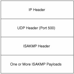
As shown in Figure 9-2, the overall ISAKMP message format consists of the following:
- An IP header
- An UDP header (port 500 [ISAKMP])
- An ISAKMP header
- One or more ISAKMP payloads
Figure 9-3 shows the ISAKMP header format.
Figure 9-3. ISAKMP Header Format
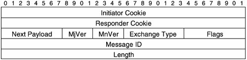
The ISAKMP header fields are as follows:
- Initiator Cookie Cookie sent by the initiator of SA creation, notification, or deletion.
Cookies can be used to verify the existence of an IPsec peer and act as identifiers (used in the course of IKE negotiation). Cookies can also help to prevent replay attacks (when an attacker resends ISAKMP messages).
In a remote access VPN environment, the initiator is almost always the remote access VPN client.
- Responder Cookie The cookie of the responder.
The responder is typically the VPN gateway in a remote access VPN environment.
- Next Payload This field indicates the type of the first payload.
Each ISAKMP message contains one or more payloads. ISAKMP payloads contain information such as security attributes (for example, IKE policy information), key exchange information, identification information, certificates, vendor-specific feature information, and so on.
- Major Version (MjVer) and Minor Version (MnVer) These two fields are used to indicate the IKE version.
- Exchange Type This indicates the IKE exchange type. Exchange types include main mode, aggressive mode, and quick mode.
- Flags There are three flags contained in this field:
- Encryption flagThis flag indicates that the ISAKMP payloads following the header are encrypted.
- Commit flagThis flag is used to ensure that encrypted messages are not received before SA establishment is complete.
- Authentication-only flagThis flag indicates that this an informational message that is authenticated but not encrypted.
- Message ID This field contains a unique, randomly generated ID that identifies an IKE phase 2 negotiation. During IKE phase 1, the Message ID is 0.
- Length This field specifies the length of the ISAKMP message, including header and payloads.
As mentioned earlier, each ISAKMP message consists of the ISAKMP message header, together with one or more payloads. Each of these payloads is prefixed by a generic payload header (see Figure 9-4).
Figure 9-4. ISAKMP Generic Payload Header Format

The fields in the ISAKMP generic payload header format are as follows:
- Next Payload When an ISAKMP message contains more that one payload, these payloads are daisy-chained together, with the Next Payload field in the header of the preceding payload indicating the contents of the following payload. If there is no following payload, the Next Payload field contains a value of 0.
- Reserved This field is unused, and must be set to 0.
- Payload Length This field specifies the length of this payload (including its generic payload header).
Now that you have an understanding of the ISAKMP message format, it is time to take a look at issues relating to IKEv1 in a remote access VPN environment.
Resolving Issues Relating to User Authentication
IKEv1 phase 1 exchanges allow IPsec devices to authenticate each other but do not include any mechanism by which remote access VPN users may be authenticated.
The distinction between the authentication of a remote access VPN device (machine) and user is important because if only the device is authenticated, it would be possible for someone to steal a legitimate user's workstation and thereby gain access to the corporate network via the VPN. If the user of the device is also authenticated, someone who steals a legitimate user's workstation/laptop will not be able to automatically gain access to the corporate network (assuming, that is, that the legitimate user's authentication credentials are not stored on the workstation/laptop).
There are three main methods by which a VPN gateway may authenticate remote access VPN users:
- Extended Authentication with IKE (Xauth)
- Hybrid Authentication Mode for IKE ("Hybrid Authentication")
- IKE Challenge/Response for Authenticated Cryptographic Keys (CRACK)
These methods of remote access VPN user authentication are discussed in the following three sections.
Extended Authentication Within IKE (Xauth)
The Xauth mechanism provides a means for a VPN client user to authenticate him/herself to a VPN gateway. The precise type of authentication can varyit could, for example, be a simple username/password authentication, challenge/response authentication, two-factor authentication, or a one-time password (OTP).
Xauth takes advantage of mechanisms and message types defined by the ISAKMP Configuration Method (described later in this chapter) and makes two minor modifications to IKEv1 phase 1 negotiation:
- Vendor ID payloads that indicate the specific version (Internet Draft) of Xauth being used are sent by the IPsec peers (this ensures consistent operation of Xauth).
- Authentication method IDs that specify the IKEv1 phase 1 authentication method, the fact that the Xauth is required after IKEv1 phase 1, and the IPsec peer that must be authenticated using Xauth (almost always the VPN client) are sent by IPsec peers.
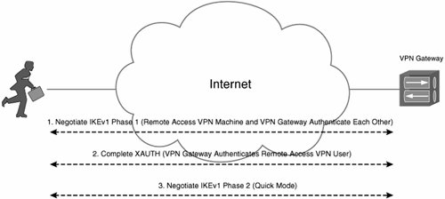
Xauth takes place only after IKEv1 phase 1 negotiation has completed successfully (and optionally periodically thereafter). When Xauth has completed, IKEv1 phase 2 negotiation takes place.
Figure 9-5 depicts Xauth.
Figure 9-5. Xauth
Xauth is supported on Cisco devices including Cisco VPN 3000 concentrators, Cisco 5500 Adaptive Security Appliances, Cisco IOS routers, PIX firewalls, as well as on the Cisco VPN Client.
It is worth noting that the SA created during IKE phase 1 protects Xauth. Xauth is vulnerable if a weak preshared key is used to authenticate IPsec peers during IKE phase 1 and, in particular, if aggressive mode is used during IKE phase 1. This is because unlike when using main mode, certain information is exchanged unencrypted when using aggressive mode, and this makes recovering a weak preshared key much easier than when using main mode.
Hybrid Authentication Mode for IKE
When using Hybrid Authentication mode for IKE (Hybrid Authentication), IKEv1 phase 1 is used to authenticate the VPN gateway only (using either RSA or DSA digital signature authentication). This is a modification to the regular IKEv1 phase 1, which is designed to authenticate both IPsec peers (both the VPN gateway and the VPN client). Both main mode and aggressive mode can be used for IKEv1 phase 1 exchange in conjunction with Hybrid Authentication.
At this point, it is important to note that although RSA or DSA digital signature authentication is used to authenticate the VPN gateway during IKEv1 phase 1, it is not necessary to deploy a full PKI. VPN gateways, but not VPN clients, need to enroll with CA servers and obtain identity certificates.
When IKEv1 phase 1 is complete, a Transaction exchange begins. This Transaction exchange consists of an ISAKMP Xauth exchange and serves to authenticate the VPN client.
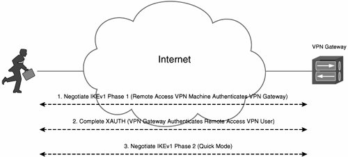
So, the VPN gateway is authenticated during IKEv1 phase 1, and the VPN client is authenticated using ISAKMP Xauth immediately after IKEv1 phase 1 is complete. If Xauth is successful, IKEv1 phase 2 negotiation takes place. Figure 9-6 illustrates Hybrid Authentication.
Figure 9-6. Hybrid Authentication
Cisco Hybrid Authentication is supported on the Cisco VPN 3000 concentrator and the Cisco VPN Client. It is not supported on Cisco IOS routers or ASA 5500s, but software releases for these platforms will add support for IKEv2.
Note that Hybrid Authentication as implemented on the Cisco VPN 3000 concentrator and Cisco VPN Client includes additional authentication using a group name and password. Authentication using the group name and password is used simply to associate remote access VPN clients with the appropriate group on the Cisco VPN concentrator.
Hybrid Authentication is implemented on Cisco VPN 3000 concentrators to address the potential weakness of regular Xauth as described in the previous section. It is also implemented to address a shortcoming of group authentication using preshared keys, which is potentially insecure because of the fact that the preshared key is common to a number of clients and a VPN gateway (it is relatively widely known and therefore more insecure), and because a remote access VPN client is not sure that it is connecting to the real VPN gateway or another device masquerading as the real VPN gateway (because the preshared key is known by a number of other clients as well as the real VPN gateway).
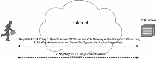
IKE Challenge/Response for Authenticated Cryptographic Keys (CRACK)
IKE CRACK consists of a modified IKE phase 1 negotiation that includes user authentication (something not included in standard IKEv1 phase 1).
When using CRACK, one of the IPsec peers (the VPN client) authenticates using a secret key type user authentication method, and the other IPsec peer (the VPN gateway) authenticates uses public-key authentication (optionally involving digital certificates).
When IKEv1 phase 1 (including CRACK) has completed successfully, IKEv1 phase 2 negotiation continues as normal.
CRACK extends the IKE standard by defining a new IKE authentication method (IKE_A_CRACK) as well as a new IKE payload (Challenge/Response payload [CHRE]). CRACK can operate in conjunction with IKEv1 phase 1 main mode and aggressive mode negotiation.
As with Hybrid Authentication, CRACK does not require the deployment of a full PKI.
Figure 9-7 illustrates CRACK.
Figure 9-7. CRACK
CRACK is supported only on the Cisco VPN 3000 concentrator beginning in software release 4.7 for use in conjunction with the VPN client on the Nokia 92xx Communicator series phones. At the time of this writing, CRACK is not supported on Cisco IOS routers, the ASA 5500, or by the Cisco VPN Client.
Resolving Issues Relating to Negotiation of Attributes Such as IP Addresses, DNS Server Addresses, and WINS Server Addresses
Because the basic IKEv1 specification cannot accomplish the assignment of configuration attributes such as IP addresses and DNS/WINS server addresses, ISAKMP Configuration Method (also known as Mode Config) was introduced. ISAKMP Configuration Method adds a new type of payload and a new type of ISAKMP message exchange. The new payload carries configuration attributes and is called the Attribute payload. The new type of exchange enables the assignment of configuration attributes and is called a Transaction exchange.
ISAKMP Configuration Method introduces two methods of configuration attribute assignment:
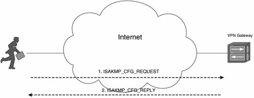
- Request (ISAKMP_CFG_REQUEST) / Reply (ISAKMP_CFG_REPLY) This method involves the exchange of Request and Replay messages. The Request message is used to request or suggest a particular configuration attribute, and the Replay message is used to supply or confirm the requested attribute.
Figure 9-8 illustrates the Request/Reply (pull) method of configuration attribute assignment.
Figure 9-8. The Request/Reply (Pull) Method of Configuration Attribute Assignment
- Set (ISAKMP_CFG_SET) / Acknowledgment (ISAKMP_CFG_ACK) When using this method of configuration attribute assignment, the configuration manager initiates the assignment of attributes, and the host acknowledges that assignment.
Figure 9-9 shows the Set/Acknowledgment (push) method of configuration attribute assignment.
Figure 9-9. Set/Acknowledgment (Push) Method of Configuration Attribute Assignment
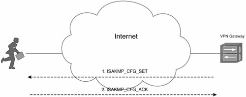
Table 9-1 shows common configuration attributes that can be assigned using ISAKMP Configuration Method.
|
Attribute Value |
Attribute |
Description |
|---|---|---|
|
0 |
RESERVED |
Unused |
|
1 |
INTERNAL_IP4_ADDRESS |
Specifies an address within the internal network |
|
2 |
INTERNAL_IP4_NETMASK |
Internal network's netmask |
|
3 |
INTERNAL_IP4_DNS |
Address of a DNS server within the network |
|
4 |
INTERNAL_IP4_NBNS |
Address of a NetBIOS Name Server (WINS) within the network |
|
5 |
INTERNAL_ADDRESS_EXPIRY |
Specifies the number of seconds that the host can use the internal IP address |
|
6 |
INTERNAL_IP4_DHCP |
Instructs the host to send any internal DHCP requests to the address contained within the attribute |
|
7 |
APPLICATION_VERSION |
Version or application information of the IPsec host |
|
8 |
INTERNAL_IP6_ADDRESS |
Specifies an address within the internal network |
|
9 |
INTERNAL_IP6_NETMASK |
Internal network's netmask |
|
10 |
INTERNAL_IP6_DNS |
Address of a DNS server within the network |
|
11 |
INTERNAL_IP6_NBNS |
Address of a NetBIOS Name Server (WINS) within the network |
|
12 |
INTERNAL_IP6_DHCP |
Instructs the host to send any internal DHCP requests to the address contained within the attribute |
|
13 |
INTERNAL_IP4_SUBNET |
Protected subnetworks that this edge device protects |
|
14 |
SUPPORTED_ATTRIBUTES |
Attributes supported |
|
15 |
INTERNAL_IP6_SUBNET |
Protected subnetworks that this edge device protects |
|
16-16383 |
Reserved for future use |
Future use |
|
16384-32767 |
Reserved for private use |
Private use |
Part I: Understanding VPN Technology
What Is a Virtual Private Network?
- What Is a Virtual Private Network?
- VPN Devices
- Deploying Site-to-Site and Remote Access VPNs: A Comparison
- Summary
- Review Questions
Part II: Site-to-Site VPNs
Designing and Deploying L2TPv3-Based Layer 2 VPNs
- Designing and Deploying L2TPv3-Based Layer 2 VPNs
- Benefits and Drawbacks of L2TPv3-Based L2VPNs
- L2TPv3 Pseudowire Operation
- Configuring and Verifying L2TPv3 Pseudowires
- Summary
- Review Questions
Designing and Implementing AToM-Based Layer 2 VPNs
- Designing and Implementing AToM-Based Layer 2 VPNs
- Benefits and Drawbacks of AToM-Based L2VPNs
- AToM Pseudowire Operation
- Deploying AToM Pseudowires
- Implementing Advanced AToM Features
- Summary
- Review Questions
Designing MPLS Layer 3 Site-to-Site VPNs
- Designing MPLS Layer 3 Site-to-Site VPNs
- Advantages and Disadvantages of MPLS Layer 3 VPNs
- MPLS Layer 3 VPNs Overview
- A Detailed Examination of MPLS Layer 3 VPNs
- Deploying MPLS Layer 3 VPNs
- Summary
- Review Questions
Advanced MPLS Layer 3 VPN Deployment Considerations
- Advanced MPLS Layer 3 VPN Deployment Considerations
- The Carriers Carrier Architecture
- The Inter-Autonomous System/Interprovider MPLS VPN Architecture
- Supporting Multicast Transport in MPLS Layer 3 VPNs
- Implementing QoS for MPLS Layer 3 VPNs
- Supporting IPv6 Traffic Transport in MPLS Layer 3 VPNs Using 6VPE
- Summary
- Review Questions
Deploying Site-to-Site IPsec VPNs
- Deploying Site-to-Site IPsec VPNs
- Advantages and Disadvantages of IPsec Site-to-Site VPNs
- IPsec: A Security Architecture for IP
- Deploying IPsec VPNs: Fundamental Considerations
- Summary
- Review Questions
Scaling and Optimizing IPsec VPNs
- Scaling and Optimizing IPsec VPNs
- Scaling IPsec Virtual Private Networks
- Ensuring High Availability in an IPsec VPN
- Designing QoS for IPsec VPNs
- MTU and Fragmentation Considerations in an IPsec VPN
- Summary
- Review Questions
Part III: Remote Access VPNs
Designing and Implementing L2TPv2 and L2TPv3 Remote Access VPNs
- Designing and Implementing L2TPv2 and L2TPv3 Remote Access VPNs
- Benefits and Drawbacks of L2TP Remote Access VPNs
- Operation of L2TP Voluntary/Client-Initiated Tunnel Mode
- Implementing L2TP Voluntary/Client-Initiated Tunnel Mode Remote Access VPNs
- Designing and Implementing L2TP Compulsory/NAS-Initiated Tunnel Mode Remote Access VPNs
- Integrating L2TP Remote Access VPNs with MPLS VPNs
- Summary
- Review Questions
Designing and Deploying IPsec Remote Access and Teleworker VPNs
- Designing and Deploying IPsec Remote Access and Teleworker VPNs
- Comparing IPsec Remote Access VPNs with Other Types of Remote Access VPNs
- Understanding IKE in an IPsec Remote Access VPN Environment
- Deploying IPsec Remote Access VPNs Using Preshared Key and Digital Signature Authentication
- Summary
- Review Questions
Designing and Building SSL Remote Access VPNs (WebVPN)
- Designing and Building SSL Remote Access VPNs (WebVPN)
- Comparing SSL VPNs to Other Types of Remote Access VPNs
- Understanding the Operation of SSL Remote Access VPNs
- Using Clientless SSL Remote Access VPNs (WebVPN) on the Cisco VPN 3000 Concentrator
- Implementing Full Network Access Using the Cisco SSL VPN Client
- Strengthening SSL Remote Access VPNs Security by Implementing Cisco Secure Desktop
- Enabling SSL VPNs (WebVPN) on Cisco IOS Devices
- Deploying SSL VPNs (WebVPN) on the ASA 5500
- Summary
- Review Questions
Part IV: Appendixes
Designing and Building SSL Remote Access VPNs (WebVPN)
- Designing and Building SSL Remote Access VPNs (WebVPN)
- Appendix A. VPLS and IPLS Layer 2 VPNs
- Understanding VPLS
- Understanding IPLS
- Summary: Comparing VPLS and IPLS
Appendix B. Answers to Review Questions
EAN: 2147483647
Pages: 124
- Chapter IV How Consumers Think About Interactive Aspects of Web Advertising
- Chapter VI Web Site Quality and Usability in E-Commerce
- Chapter XI User Satisfaction with Web Portals: An Empirical Study
- Chapter XIII Shopping Agent Web Sites: A Comparative Shopping Environment
- Chapter XV Customer Trust in Online Commerce
