L2TPv3 Pseudowire Operation
L2TPv3 is, as previously described, a tunneling protocol that can be used for transporting Layer 2 protocols. It can operate in a number of different configurations (one of which is discussed in this chapter) and tunnel a number of different Layer 2 protocols and connections over a packet-switched network (PSN). This chapter assumes that the PSN over which L2TPv3 tunnels Layer 2 protocols is an IP network.
L2TPv3 can transport a number of Layer 2 protocols and connection types, including the following:
- Ethernet
- Ethernet VLAN (802.1Q)
- Frame Relay
- HDLC and HDLC-like protocols
- PPP
- ATM (both ATM Adaption Layer 5 [AAL5] and cell relay)
To understand L2TPv3 pseudowires, it is essential to have a firm grasp of the following:
- L2TPv3 deployment models
- L2TPv3 message types
- The L2TPv3 control connection
L2TPv3 deployment models, message types, and the control connection are examined in the following three sections.
L2TPv3 Deployment Models
There are three basic deployment models for L2TPv3:
- L2TP Access Concentrator (LAC)-to-L2TP Network Server (LNS)
- LAC-to-LAC
- LNS-to-LNS
A LAC functions as a cross-connect between data links and L2TP sessions (emulated Layer 2 connections), whereas an LNS terminates L2TP sessions and processes the encapsulated Layer 3 protocol packets on virtual interfaces.
The LAC-to-LAC model is used to configure the L2TPv3 pseudowire-based VPNs discussed in this chapter. The LAC-to-LNS and LNS-to-LNS models are discussed further in Chapter 8, "Designing and Implementing L2TPv2 and L2TPv3 Remote Access VPNs."
Figure 2-1 illustrates the LAC-to-LAC deployment model.
Note
A pseudowire is an emulated circuit that crosses a PSN. One pseudowire corresponds to one L2TPv3 session.
L2TPv3 Message Types
L2TPv3 uses two types of message:
- Control connection messages Used for signaling between LCCEs
- Session data (channel) messages Used to transport Layer 2 protocols and connections
Figure 2-2 shows the format of control channel and session data (channel) messages.
Figure 2-2. Control Channel and Data Channel Messages
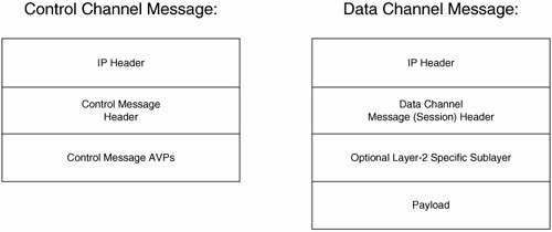
As shown in Figure 2-2, the control channel message consists of the following:
- The IP packet header. The protocol ID contained in the header is 115 (L2TPv3).
Note
L2TPv3 control and data channel messages can be carried either directly over IP (protocol ID 115) or over IP/UDP (UDP port 1701). On Cisco routers, L2TPv3 control and data messages are carried directly over IP in a LAC-to-LAC deployment.
- The control message header.
- Control message attribute-value pairs (AVP). AVPs are used to specify a variable (the attribute) and the value associated with that variable.
AVPs perform a number of functions, including the following:
- General functions such as control channel message authentication and integrity
- Communicating error and result codes and messages
- Communicating control connection management information such as host names, router IDs, supported pseudowires types, control connection IDs, session IDs, required Layer 2specific sublayers, connection speeds, and any data-sequencing requirements
- Communicating circuit status and error information
Figure 2-3 shows the control connection message header format.
Figure 2-3. L2TPv3 Control Connection Message Header (over IP) Format

The fields of the control connection message header shown in Figure 2-3 have the following functions:
- The first field consists of 32 bits that must all be set to 0. This field identifies this message as a control message.
- The T, L, and S flags:
- The T bit must be set to 1 and identifies this as a control connection message (along with the 32 bits of 0s).
- The L bit must be set to 1 and indicates that the Length field is present in the message.
- The S bit must be set to 1 and indicates that the Next Sent (Ns) and Next Received (Nr) fields are present in the control channel message.
- The Version (Ver) field must contain the value 3 to indicate that this is an L2TPv3 control channel message.
- The Length field specifies the length of the control channel message beginning with the Flags field.
- The Control Connection ID uniquely identifies the control channel (more than one control channel may be established on a particular LCCE).
- The Next Sent (Ns) field indicates the sequence number of this message.
- The Next Received (Nr) field indicates the sequence number of the next control channel message expected from the peer LCCE.
The data channel message shown in Figure 2-2 consists of the following:
- The IP header (protocol ID 115)
- The Data Channel Message (Session) header
- An optional Layer 2specific sublayer
- The payload, which carries the Layer 2 protocol frames, cell(s), or Service Data Unit (SDU) received by an LCCE on an attachment circuit (from a CE device).
Figure 2-4 depicts the L2TPv3 Data Channel (Session) Message header.
Figure 2-4. L2TPv3 Session Header (over IP)
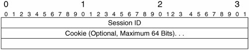
The fields in the L2TPv3 data channel message are as follows:
- Session ID, which uniquely identifies this L2TPv3 session.
- Cookie, which is optional, and can be used in combination with the Session ID to ensure that a data channel message is correctly associated with the appropriate local attachment circuit, as well as offering a certain level of protection against blind-insertion attacks.
Blind-insertion attacks involve an attacker attempting to insert malicious packets into an L2TPv3 data channel message stream (without being able to directly sniff the data channel). The cookie helps to protect against these insertion attacks because an attacker will find it difficult to guess the cookie (assuming that the cookie is randomly chosen).
The cookie, if present, can be either 32 or 64 bits in length.
Figure 2-5 shows the optional Layer 2specific sublayer shown in the data channel message (refer to Figure 2-2 for the overall data channel message format).
Figure 2-5. Optional Default Layer 2Specific Sublayer
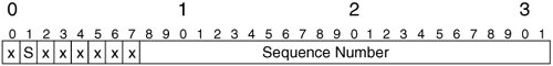
The S flag in the default Layer 2 specific sublayer is set to 1 if sequencing of data channel messages is enabled. In this case, a non-0 sequence number will be contained in the Sequence Number field.
The L2TPv3 Control Connection
Control connection messages are used for the following functions:
- Setting up the control connection itself
- Dynamically establishing L2TPv3 sessions
- Providing a keepalive mechanism for the control connection and sessions
- Signaling circuit status changes
- Tearing down L2TP sessions, as well as the control connection itself
These various functions are explained in this section.
Note
A LAC that participates in a control connection can also be referred to as an L2TP Control Connection Endpoint (LCCE).
The acronyms PE router, LAC, and LCCE are used interchangeably in this chapter. The one exception is the discussion later in this chapter of static L2TPv3 sessions without a control connection between PE routers/LACs. In this case, the terms PE router and LAC may be used, but the term LCCE is not used simply because without a control connection being established, a PE router/LAC cannot be considered the endpoint of a control connection.
L2TPv3 Control Connection Setup
Figure 2-6 illustrates control connection setup.
Figure 2-6. Control Connection Setup
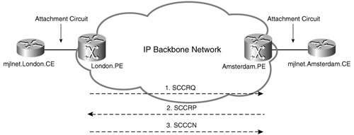
As you can see in Figure 2-6, control connection setup consists of the exchange of three messages between LCCEs:
|
Step 1. |
One LCCE (London.PE, in Figure 2-1) sends a Start-Control-Connection-Request (SCCRQ) message to its peer.
The SCCRQ, as well as other control channel messages, carry authentication information if authentication is configured. |
||||||||||||||||||||||
|
Step 2. |
If the SCCRQ is acceptable, the peer LCCE (Amsterdam.PE) responds with a Start-Control-Connection-Reply (SCCRP) message. |
||||||||||||||||||||||
|
Step 3. |
The LCCE that sent the SCCRQ (London.PE) now responds to the SCCRP with a Start-Control-Connection-Connected (SCCCN) message indicating completion of control channel setup. |
That is the theory of control channel setup. Example 2-1 shows L2TPv3 control connection establishment in practice.
Example 2-1. L2TPv3 Control Connection Setup Between Two Cisco LCCEs
Amsterdam.PE#debug vpdn l2x-events L2X protocol events debugging is on Amsterdam.PE# 00:16:46: L2TP: I SCCRQ from London.PE tnl 23658 (line 1) 00:16:46: Tnl47781 L2TP: Message digest match performed, passed. 00:16:46: Tnl47781 L2TP: Control connection authentication skipped/passed. 00:16:46: Tnl47781 L2TP: New tunnel created for remote London.PE, address 172.16.1.1 00:16:46: Tnl47781 L2TP: O SCCRP to London.PE tnlid 23658 (line 2) 00:16:46: Tnl47781 L2TP: Control channel retransmit delay set to 1 seconds 00:16:46: Tnl47781 L2TP: Tunnel state change from idle to wait-ctl-reply 00:16:46: Tnl47781 L2TP: Tunnel state change from wait-ctl-reply to established 00:16:46: Tnl47781 L2TP: I SCCCN from London.PE tnlid 23658 (line 3) 00:16:46: Tnl47781 L2TP: Control channel retransmit delay set to 1 seconds 00:16:46: Tnl47781 L2TP: SM State established (line 4) Amsterdam.PE# |
In highlighted line 1, Amsterdam.PE receives a SCCRQ from London.PE. The SCCRQ is acceptable, and Amsterdam.PE responds with an SCCRP in highlighted line 2. Highlighted line 3 shows that an SCCCN has been received from London.PE. Finally, the control channel state changes to established (highlighted line 4).
L2TPv3 Control Connection Teardown
If an LCCE wants to tear down a control connection, it can signal this to its peer LCCE using a Stop-Control-Connection-Notification (StopCCN) message (see Figure 2-7).
Figure 2-7. Control Connection Teardown
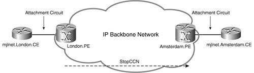
An LCCE can choose to tear down a control channel for a number of reasons, including if an administrator uses the clear l2tun command to manually request control channel teardown.
Example 2-2 shows control connection teardown.
Example 2-2. Control Connection Teardown
Amsterdam.PE#debug vpdn l2x-events L2X protocol events debugging is on Amsterdam.PE# 03:39:51: Tnl28072 L2TP: Perform early message digest validation for StopCCN 03:39:51: Tnl28072 L2TP: No message digest AVP, skip validation. 03:39:51: Tnl28072 L2TP: Control connection authentication skipped/passed. 03:39:51: Tnl28072 L2TP: I StopCCN from London.PE tnl 64207 (line 1) 03:39:51: Tnl28072 L2TP: Shutdown tunnel 03:39:51: Tnl28072 L2TP: Tunnel state change from established to idle (line 2) Amsterdam.PE# |
Amsterdam.PE receives a StopCCN message from London.PE in highlighted line 1. In highlighted line 2, the tunnel (control channel) state changes from established to idle. The control channel has been torn down. That is control channel setup and teardown. But how about L2TPv3 session setup and teardown?
L2TPv3 Session Setup
After a control connection has been set up (see Figure 2-6), dynamic session (pseudowire) establishment can begin, as shown in Figure 2-8.
Figure 2-8. L2TPv3 Session (Pseudowire) Setup
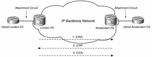
L2TPv3 session setup consists of the exchange of three messages:
|
Step 1. |
The LAC that wants to set up a session (London.PE, in this example) sends an Incoming-Call-Request (ICRQ) message to its peer LAC (Amsterdam.PE, in this example). |
|
Step 2. |
If the peer LAC (Amsterdam.PE) accepts the ICRQ, it responds with an Incoming-Call-Response (ICRP) message. |
|
Step 3. |
Finally, the LAC that wants to set up the session (London.PE) sends an Incoming-Call-Connected (ICCN) message to its peer LAC (Amsterdam.PE) to complete session setup. |
Example 2-3 shows L2TPv3 session setup.
Example 2-3. L2TPv3 Session Setup Between Two LACs
London.PE#debug vpdn l2x-events L2X protocol events debugging is on London.PE# 00:16:46: Tnl/Sn11744/5823 L2TP: O ICRQ to Amsterdam.PE 34855/0 (line 1) 00:16:46: Tnl/Sn11744/5823 L2TP: Session state change from wait-for-tunnel to wait-reply 00:16:46: Tnl11744 L2TP: Perform early message digest validation for ICRP (line 2) 00:16:46: Tnl11744 L2TP: Message digest match performed, passed. 00:16:46: Tnl11744 L2TP: Control connection authentication skipped/passed. 00:16:46: Tnl/Sn11744/5823 L2TP: O ICCN to Amsterdam.PE 34855/64191 (line 3) 00:16:46: Tnl11744 L2TP: Control channel retransmit delay set to 1 seconds 00:16:46: Tnl/Sn11744/5823 L2TP: Session state change from wait-reply to established (line 4) London.PE# |
In highlighted line 1, London.PE sends an ICRQ message to Amsterdam.PE. Amsterdam.PE replies with the ICRP message shown in highlighted line 2. Highlighted line 3 shows that London.PE now send an ICCN message to Amsterdam.PE. In highlighted line 4, you can see that the L2TPv3 session has now become established. After the L2TPv3 session has been established, data traffic can be transported between the attachment circuits over the pseudowire.
L2TPv3 Session Teardown
An LCCE can dynamically request that a session be torn down by sending a Call-Disconnect-Notify (CDN) message (see Figure 2-9).
Figure 2-9. L2TPv3 Session (Pseudowire) Teardown
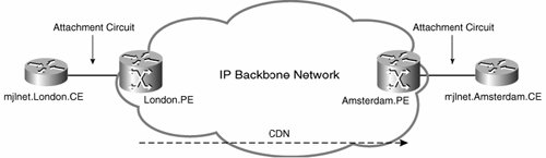
An LCCE can choose to tear down a session for a range of reasons. One reason is if an LCCE receives an ICRQ message containing a virtual circuit (VC) ID that is not configured on the local LCCE (VC IDs are used to associate local and remote attachment circuits with a pseudowire).
Example 2-4 shows the transmission of a CDN message when an ICRQ is received that contains a VC ID that it does not recognize.
Example 2-4. Transmission of a CDN Message
London.PE#debug vpdn l2x-events L2X protocol events debugging is on London.PE# 02:53:53: Tnl56029 L2TP: Perform early message digest validation for ICRQ 02:53:53: Tnl56029 L2TP: No message digest AVP, skip validation. 02:53:53: Tnl56029 L2TP: Control connection authentication skipped/passed. 02:53:53: Tnl56029 L2TP: I ICRQ from Amsterdam.PE tnl 21530 (line 1) 02:53:53: Tnl/Sn56029/9629 L2TP: Session state change from idle to wait-connect 02:53:53: Tnl/Sn56029/9629 L2TP: Accepted ICRQ, new session created (line 2) 02:53:53: Tnl/Sn56029/9629 L2TP: Xconnect VC ID 1002 not provisioned (line 3) 02:53:53: Tnl/Sn56029/9629 L2TP: O CDN to Amsterdam.PE 21530/8987 (line 4) 02:53:53: Tnl56029 L2TP: Control channel retransmit delay set to 1 seconds 02:53:53: Tnl/Sn56029/9629 L2TP: Destroying session (line 5) 02:53:53: Tnl/Sn56029/9629 L2TP: Session state change from wait-connect to idle (line 6) London.PE# |
Highlighted line 1 shows that London.PE has received an ICRQ from its peer, Amsterdam.PE. In line 2, London.PE apparently accepts the ICRQ and creates a new session. But, in highlighted line 3, London.PE reports that the VC ID (1002) contained in the ICRQ is not provisioned on the local LCCE (London.PE). Because London.PE does not recognize the VC ID, it sends a CDN message to tear down the session (see highlighted line 4).
Then, in highlighted lines 5 and 6, London.PE reports that it is destroying the session, and the session state changes to idle. The session has been torn down.
Okay, that is control channel and session setup and teardown. There are, however, another couple of messages that you need to know to complete your understanding of the control channel (as far as the LAC-to-LAC model is concerned)the Hello and the Set-Link-Info (SLI) messages.
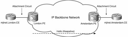
Hello and SLI Messages
In the absence of any messages (whether control messages or data session messages) from its peer, a LAC sends a Hello message to check that it still has connectivity to its peer, and that its peer is still alive.
The period of inactivity that will cause a LAC to send a Hello message to its peer is configurable but defaults to 60 seconds.
Figure 2-10 illustrates the transmission of a Hello message.
Figure 2-10. Transmission of a Hello Message
Example 2-5 shows the transmission of a Hello message.
Example 2-5. Transmission of a Hello Message
London.PE#debug vpdn l2x-events L2X protocol events debugging is on London.PE# 00:17:46: Tnl11744 L2TP: O Hello to Amsterdam.PE tnlid 34855 (line 1) 00:17:46: Tnl11744 L2TP: Control channel retransmit delay set to 1 seconds 00:17:46: Tnl11744 L2TP: Perform early message digest validation for ACK (line 2) 00:17:46: Tnl11744 L2TP: Message digest match performed, passed. 00:17:46: Tnl11744 L2TP: Control connection authentication skipped/passed. London.PE# |
Highlighted line 1 shows the transmission of a Hello message to Amsterdam.PE. Then, in highlighted line 2, an acknowledgment (ACK) is received from Amsterdam.PE (it's alive!).
Another function of the control channel is to signal circuit status changes using the SLI message as illustrated in Figure 2-11.
Figure 2-11. Signaling Circuit Status Changes Using the SLI Message
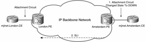
In Figure 2-11, the attachment circuit between Amsterdam.PE and mjlnet.Amsterdam.CE has changed state to down, and so Amsterdam signals this to London.PE using the SLI message.
Note
For detailed, step-by-step, information on debugging and troubleshooting L2TPv3-based VPNs, refer to Troubleshooting Virtual Private Networks by Mark Lewis (Cisco Press).
Part I: Understanding VPN Technology
What Is a Virtual Private Network?
- What Is a Virtual Private Network?
- VPN Devices
- Deploying Site-to-Site and Remote Access VPNs: A Comparison
- Summary
- Review Questions
Part II: Site-to-Site VPNs
Designing and Deploying L2TPv3-Based Layer 2 VPNs
- Designing and Deploying L2TPv3-Based Layer 2 VPNs
- Benefits and Drawbacks of L2TPv3-Based L2VPNs
- L2TPv3 Pseudowire Operation
- Configuring and Verifying L2TPv3 Pseudowires
- Summary
- Review Questions
Designing and Implementing AToM-Based Layer 2 VPNs
- Designing and Implementing AToM-Based Layer 2 VPNs
- Benefits and Drawbacks of AToM-Based L2VPNs
- AToM Pseudowire Operation
- Deploying AToM Pseudowires
- Implementing Advanced AToM Features
- Summary
- Review Questions
Designing MPLS Layer 3 Site-to-Site VPNs
- Designing MPLS Layer 3 Site-to-Site VPNs
- Advantages and Disadvantages of MPLS Layer 3 VPNs
- MPLS Layer 3 VPNs Overview
- A Detailed Examination of MPLS Layer 3 VPNs
- Deploying MPLS Layer 3 VPNs
- Summary
- Review Questions
Advanced MPLS Layer 3 VPN Deployment Considerations
- Advanced MPLS Layer 3 VPN Deployment Considerations
- The Carriers Carrier Architecture
- The Inter-Autonomous System/Interprovider MPLS VPN Architecture
- Supporting Multicast Transport in MPLS Layer 3 VPNs
- Implementing QoS for MPLS Layer 3 VPNs
- Supporting IPv6 Traffic Transport in MPLS Layer 3 VPNs Using 6VPE
- Summary
- Review Questions
Deploying Site-to-Site IPsec VPNs
- Deploying Site-to-Site IPsec VPNs
- Advantages and Disadvantages of IPsec Site-to-Site VPNs
- IPsec: A Security Architecture for IP
- Deploying IPsec VPNs: Fundamental Considerations
- Summary
- Review Questions
Scaling and Optimizing IPsec VPNs
- Scaling and Optimizing IPsec VPNs
- Scaling IPsec Virtual Private Networks
- Ensuring High Availability in an IPsec VPN
- Designing QoS for IPsec VPNs
- MTU and Fragmentation Considerations in an IPsec VPN
- Summary
- Review Questions
Part III: Remote Access VPNs
Designing and Implementing L2TPv2 and L2TPv3 Remote Access VPNs
- Designing and Implementing L2TPv2 and L2TPv3 Remote Access VPNs
- Benefits and Drawbacks of L2TP Remote Access VPNs
- Operation of L2TP Voluntary/Client-Initiated Tunnel Mode
- Implementing L2TP Voluntary/Client-Initiated Tunnel Mode Remote Access VPNs
- Designing and Implementing L2TP Compulsory/NAS-Initiated Tunnel Mode Remote Access VPNs
- Integrating L2TP Remote Access VPNs with MPLS VPNs
- Summary
- Review Questions
Designing and Deploying IPsec Remote Access and Teleworker VPNs
- Designing and Deploying IPsec Remote Access and Teleworker VPNs
- Comparing IPsec Remote Access VPNs with Other Types of Remote Access VPNs
- Understanding IKE in an IPsec Remote Access VPN Environment
- Deploying IPsec Remote Access VPNs Using Preshared Key and Digital Signature Authentication
- Summary
- Review Questions
Designing and Building SSL Remote Access VPNs (WebVPN)
- Designing and Building SSL Remote Access VPNs (WebVPN)
- Comparing SSL VPNs to Other Types of Remote Access VPNs
- Understanding the Operation of SSL Remote Access VPNs
- Using Clientless SSL Remote Access VPNs (WebVPN) on the Cisco VPN 3000 Concentrator
- Implementing Full Network Access Using the Cisco SSL VPN Client
- Strengthening SSL Remote Access VPNs Security by Implementing Cisco Secure Desktop
- Enabling SSL VPNs (WebVPN) on Cisco IOS Devices
- Deploying SSL VPNs (WebVPN) on the ASA 5500
- Summary
- Review Questions
Part IV: Appendixes
Designing and Building SSL Remote Access VPNs (WebVPN)
- Designing and Building SSL Remote Access VPNs (WebVPN)
- Appendix A. VPLS and IPLS Layer 2 VPNs
- Understanding VPLS
- Understanding IPLS
- Summary: Comparing VPLS and IPLS
Appendix B. Answers to Review Questions
EAN: 2147483647
Pages: 124
- ERP System Acquisition: A Process Model and Results From an Austrian Survey
- Enterprise Application Integration: New Solutions for a Solved Problem or a Challenging Research Field?
- The Effects of an Enterprise Resource Planning System (ERP) Implementation on Job Characteristics – A Study using the Hackman and Oldham Job Characteristics Model
- Relevance and Micro-Relevance for the Professional as Determinants of IT-Diffusion and IT-Use in Healthcare
- Development of Interactive Web Sites to Enhance Police/Community Relations
