| In Maya, every view relates to a camera. When Maya starts, you have four cameras by default: front, side, top and perspective. Three of them are orthographic flat, non-perspective views and have visible icons you can use to translate or rotate the camera. The icon for the perspective camera is, by default, invisible. These four cameras are utility views that assist you in modeling and laying out your scene. When you're ready to pick the final rendered viewpoint of your scene, you should create a scene camera. If you're shooting a series of stills, you can create many cameras, one for each shot. (However, often it's easier to move a single camera to different positions in sequential frames, starting with frame 1, so that you can render the job more easily in batch rendering.) Or you might have several animated cameras that fly through the scene from varying angles, creating several different video clips of the same scene that are rendered separately. The camera placement determines exactly what will be seen and is used to frame specific portions of the scene, in the same way illustrators or photographers use composition to frame certain elements in their paintings and drawings. Other key variables for cameras are focal length, rotation (orientation), and angle of view. Focal length is directly linked to angle of view; if one goes up, the other goes down. With angle of view, as the angle of the lens widens, you must move the camera closer to the subject to keep it at the same relative size in the frame. The wider the angle, the higher the value for the Angle of View setting. Figure 13.1 illustrates four settings for Angle of View. Figure 13.1. Clockwise from top left: a wide-angle (90 degree) closeup view, a normal (55 degree) view, a zoom (17 degree) view, and an orthographic (0 degree) view. 
Creating Cameras There are three types of perspective cameras in Maya, described in the following list (see Figure 13.2). As with Maya's lights, you can change a camera to any other camera type in the Attribute Editor. Camera With this camera type, you see only the camera icon (the next two types add manipulator handles to the camera icon). In general, because this camera freely rotates and loses track of its "up" vector (as shown in the rotating camera at far right in Figure 13.2), you should use it only when you're linking the camera to another object for movement and animation (as in the tutorial in Chapter 4, "Diving In: Your First Animation"), or when you're placing a camera in one fixed spot. Camera and Aim This camera includes a camera target (in other words, what the camera is looking at) and an aim handle for adjusting the camera target. In addition, this camera automatically stays level in relation to the horizon, so it's the one you'll use most often. You can make this camera roll if you want, but by default, it stays level except at extreme straight-up or straight-down orientations. Camera, Aim and Up This camera type includes two handles: the aim handle, described for Camera and Aim, and an up handle for banking (leveling) the camera. This camera type is useful when you want to bank the camera during your animation. Note that you must select both the camera and the up handle when you move the camera, or the up handle will remain in place as you move the camera, causing unwanted banking.
Figure 13.2. The three camera types, left to right: Camera; Camera and Aim; and Camera, Aim and Up. To rotate cameras, click in the circle shown at the right. 
tip When Maya starts, you see a Perspective view with its own default "persp" camera. This Perspective view is useful for navigating around your scene to find the areas you want to focus on and to edit those areas in 3D. You can create additional cameras and use them for "official" render cameras or as additional test perspective cameras like the default perspective camera. Usually, however, it's better not to use the default perspective camera as your scene's render camera because it's too easy to unintentionally move or alter.
Camera Settings With a camera selected, you can open the Attribute Editor and expand the Camera Attributes section to see all the variables for the camera, as shown in Figure 13.3. Figure 13.3. The attributes for cameras. 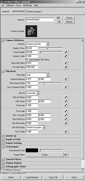
These are the key settings for cameras under the Camera Attributes section: Controls In this drop-down list, you can quickly select the camera type you want. Angle of View and Focal Length Controls the amount of perspective exaggeration. Raising the Angle of View attribute lowers the Focal Length attribute. For example, in Figure 13.1's top-left image, the angle of view has been raised to 90 degrees, so the focal length is shortened to 18, thus producing a closeup view with heightened foreshortening, most noticeable in the distorted torus shape. Camera Scale You can change the camera size in relation to your scene, which affects scene objects when you render. Camera Scale is like a multiplier for the Angle of View setting. For example, decreasing Camera Scale to .5 halves the camera's view area, but makes objects in the scene look twice as large. Clip Planes Only objects located within the values specified for the camera's clip planes appear in the scene. If distant objects are not showing up in your scene, raise the Far Clip Plane value. If nearby objects seem to be appearing in cross-section or not appearing at all, lower the Near Clip Plane value. Depth of Field Enable distance blur with this attribute. It can be a render-intensive effect, but yields a nice cinematic result because objects close to and far away from the focus point are progressively blurred. Background Color The background fill color for images rendered from this camera; you can also use this section of the Attribute Editor to add an image or shader as the background. Orthographic Views Switches the camera to an orthographic view (such as Side, Top, or Front), which has no perspective distortion. You can create perspective cameras, rotate them into position, and then set them to orthographic to get a "flat" view for projecting textures onto an object.
tip The Film Offset settings under the Film Back section are helpful for architectural animators who want to avoid vertical perspective distortion. If you've set your camera to a view that causes vertical distortion (refer to Chapter 1, "Pre-Maya: A Primer," and look at the rightmost image in Figure 1.10), you can adjust these values to get rid of the distortion. First, you must raise or lower the camera itself, so that it's horizontal; this removes all vertical distortion. Then, use the offset settings to frame the portion of the image you want to render. The Film Offset X and Y values (X is the left text box; Y is the right) reposition where the camera "looks" in relation to the target.
Animating the Camera When you first begin animating the camera, it helps to follow the rules of videography, such as avoiding jarring camera motions rapid pans, zooms, or rotations of the camera. In addition, you should usually give the camera the impression of having mass. The virtual camera, by default, starts and stops moving instantly, which looks unrealistic and abrupt to viewers. To avoid this problem, adjust the tangents for the camera position's start and stop keys in the Graph Editor so that motion begins and ends gradually (refer to Chapter 11, "Animation Basics," for more information on adjusting tangents). Do the same for the camera's aim point keys and any other animated camera attributes if you want to get a smooth look. Of course, if you're after the "reality TV" look, you'll have no problem creating a shaky, off-kilter camera in Maya. It's the "cinematic" look that takes some work. You'll explore smoothing the camera's action in the next tutorial. tip You can make a panel "look through" any scene element (object, camera, light, and so forth). Choose Panels | Look Through Selected on the panel's menu bar, and the panel switches to the viewpoint of the currently selected scene element. Most of the time, you do this only to check the aim of Spot and Directional lights, but this method can also be helpful when you want a quick look at the scene from an object's point of view. If you have the camera look through objects, you're viewing from the object's local Z axis.
Tutorial: Easing the Camera's Motion In this tutorial, you'll animate a camera and then adjust its animation keys for smooth motion. You want the camera to enter the lobby and swing right to see the planter area. The camera then makes its way through the lobby and enters the elevator. After you set position keys for the camera and its target, you'll give the camera the appearance of mass by adjusting the tangents for the camera and the target's start and stop keys so that motion transitions are more gradual. On the DVD  Chapter_13\movies\ch13tut01.wmv |
On the DVD  Chapter_13\ch13tut01begin.mb |
Make sure you're in Four View mode (if not, tap the spacebar to switch). Create a camera (Create | Cameras | Camera and Aim). It's automatically named camera2 in this scene because you already placed a camera in Chapter 11. First, select Camera2_group in the Outliner (hotkey: Alt+o). In the Channel Box, set Translate X, Y, and Z to 0, 34.85, and 260.16. Set Scale X, Y, and Z to 4 so that the camera icon is bigger and easier to select. Next, select only camera2 in the Outliner, activate the Perspective view, and choose Panels | Look through Selected. Your shaded view is now the camera's view; as you move the camera, you'll see the shaded view update. In the Outliner, expand Camera2_group, and select the camera's aim point, named camera2_aim. Set its Translate X, Y, and Z to 0, 0, and -16 in the Channel Box. Then, select Camera 2 and set its Translate X, Y, and Z to 2.672, 0, 0. In the Status Line, click the down arrow to the left of the Select by Object/Component Type (selection mask) buttons, and select All Objects Off, as shown in Figure 13.4. Right-click on the Rendering selection mask button (the blue sphere), and choose Cameras. Now, you can select only cameras in your scene, which will make the animation process easier. Figure 13.4. Using the selection mask buttons. 
Select Camera 2, and then Shift-click on the aim point to select its target camera2_view. In the Time Slider, confirm that the current frame is set to 0, and set an animation key for just the Translate values (hotkey: Shift+w). Deselect the camera and target by clicking in a blank area of the Camera 2 view (the Perspective view). tip Normally, you set keys by using the s hotkey, but you can also use Shift+w, Shift+e, and Shift+r to set keys for Translate, Rotate, and Scale without affecting other keys. By default, the s hotkey sets keys on all the attributes, which isn't usually what you want. Adding keys to elements that aren't animated can cause a lot of trouble if you decide later that you do want to animate those attributes. Drag the Time Slider to frame 30. Switch to Move mode (hotkey: w). In the Top view, move camera2_aim up (Translate settings: 0, 0, -24), and set a key (hotkey: s). Select Camera 2 and move it up and to the right so that Translate X is roughly 2.696 and Translate Z is about 10.9. Set a key (the Channel Box will reflect the camera's current position as you move it). As you pull the Time Slider over to 30, you should see the door open. Set your current frame on the Time Slider back to 0. Next, you'll set a key but change the defaults so that the s hotkey works only for the current manipulator type in this case, the Translate values because you're in Move mode. To do this, choose Hotbox | Animate | Set Key | option box. Change the Set Keys On radio button to Current Manipulator Handle, and then click the Set Key button. From now on, the s hotkey will create keys only for the current manipulator. Set the Time Slider to 60. With Camera 2 still selected, move it slightly up and left so that it avoids the front glass door closing. The Translate X, Y, and Z settings should be about 1.524, 0, and -17.112. Set a Translate key for frame 60 (hotkey: s). Select the camera2_aim object. Set its Translate X, Y, and Z to 0, 0, and -32 and then set a key frame. Drag the Time Slider to frame 80. Shift-click the aim handle and Camera 2. In the Top view, move them together up and to the left so that they're near the center of the lobby. Set a key by pressing s (which sets a key for the Translate values of both the camera and target). The Translate settings for camera2_aim are 2.104, 0, -44.991; for Camera 2, they are 1.524, 0, -37.102. If you reposition the camera closer to these settings, be sure to set a key again to overwrite the keys on that frame for each object. tip You can overwrite previously set keys by setting a new key for the same attribute on a frame that currently has a key. Drag the Time Slider to frame 100. In the Top view, move Camera 2 up to a position that's about 11.694 and 94.093 for Translate X and Z; the sight line to the target will be vertical. Check the Camera 2 view and adjust the camera's position if you want it slightly closer to or farther away from objects in the scene. Set a key for the camera, and then select camera2_aim and set a key for it, too. With the target aim selected, drag the Time Slider to frame 120. Move camera2_aim to 26.481, 0, -114.895 for Translate X, Y, and Z. Then, set a key for camera2_aim. Select Camera 2, and move it up and to the right until it's pointed into the elevator. Set a key. In the Channel Box, the Translate settings should be around -14.676, 0, and -111.983. Right-click the shaded Camera 2 view to activate it, and then click the Play button in the playback controls to the right of the Time Slider. Notice that the camera motion is fairly smooth, but it starts and stops abruptly, especially after getting past the front door. Make sure Camera 2 is still selected, and view the camera trajectory by choosing Hotbox | Animate | Create Motion Trail | option box. In the Motion Trail Options dialog box (see Figure 13.5), set the Start Time and End Time frames to 1 and 120, and select the Line radio button for the Draw Style option. Clear the Show Frame Numbers check box, and click the Create Motion Trail button. You can then see a line that illustrates Camera 2's path. Do the same for the camera target. These paths, generated by the keys you set, can be helpful for visualizing what you've animated, and they are updated as you adjust keys. To see these motion trails in action, try moving the camera when the Time Slider is at one of the keys and setting a new keyframe. After you release the mouse button, the curve will update. Press Ctrl+z to undo. Figure 11.5. Creating a motion trail for the animated camera. 
Make sure Camera 2 is selected. Open the Graph Editor (Hotbox | Window | Animation Editors | Graph Editor). Click f to focus the window, and you'll see lines representing the camera's motion curves. Click and drag over the three Translate labels in the Graph Editor Outliner. The graph changes to display just these three attributes. Now, frame the view (hotkey: f) so that the motion curves fill the Graph view. Marquee-select the leftmost points of the red, green, and blue motion curves in the Graph view. Hold down the Shift key and do the same for the rightmost points of each curve. Then, Shift+click over the center point where the center of interest is curved, but needs to be leveled out. Right-click on one of the endpoints, and choose Tangents | Flat. All the tangents become horizontal at their beginning and ending points (see Figure 13.6). The result on the animation is that the motion picks up speed as it begins and slows more gradually at the end. Figure 13.6. Editing the tangents of the curves' endpoints in the Graph Editor. 
Minimize the Graph Editor, right-click the Camera 2 viewport to make it active, and play the animation. The moving camera's view should play back in a loop, and the starting and stopping actions at the end of the animation should be smoother. Notice that Camera 2 still speeds up unrealistically as it races to the elevator. A more even pace would suit this scene better, so you'll adjust the keys further using the Graph Editor. First, maximize the Graph Editor. The increase in speed starts around frame 60, so in step 18, you need to expand the number of frames from that point to cover more time. The result is that the camera will take more time to get to the elevator and, therefore, travels more smoothly. In the Graph Editor, marquee-select all the keys for Camera 2 and camera2_aim from frame 60 to frame 120. Switch to Scale mode (hotkey: r). Hold down the Shift key, and click and drag to the right until the new keyframe range has been extended to 300 frames of animation. tip When you're scaling keys in the Graph Editor, all selected keys scale from where the cursor begins. To scale forward in time, be sure to place your cursor directly above the first selected key in the set to scale from. To view the entire animation, you'll have to reset the focus in the Range Slider just below the Time Slider. Set the ending time to 300, and play through the animation. You can compare your final version with the finished scene file noted next to the DVD icon, if you like. On the DVD Chapter_13\ch13tut01end.mb |
|