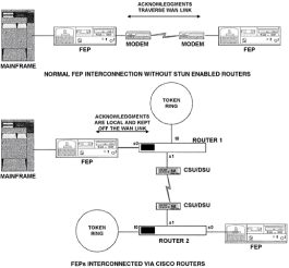
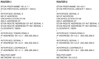
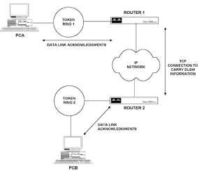
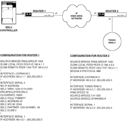
Chapter 5 - Adding Support for Legacy LANs. (cisco router management)

Chapter 5: Adding Support for Legacy LANs  
  Objectives  
  In this chapter we will examine:  
    How we can use Cisco routers to transport protocols other than TCP/IP.  
    Network protocols included in corporate networks, such as Novell NetWare's IPX, the IBM SNA protocols, and Windows NT NetBEUI.  
    An overview of how bridging technology is implemented on Cisco routers.  
  The approach will be to give an overview of each technology, discuss integrating each protocol into a TCP/IP environment, and then give configuration examples of how to implement these protocols on Cisco routers.
Novell NetWare's IPX/SPX Protocols  
  Novell's NetWare product, which is installed in more than 50 percent of LANs worldwide, uses the IPX/SPX (Internetwork Packet Exchange and Sequenced Packet Exchange) protocol as its basis for communications. NetWare was designed as a departmental server operating system, originally meant to service up to 100 users. Novell's marketing strategy was to aim for the departments that did not want to wait in line for corporate MIS departments to deliver systems that they could instead buy off the shelf. This strategy was well-timed it coincided with cheap, powerful PCs becoming available and became phenomenally successful.  
  To make it as easy as possible for departments to implement a LAN protocol, Novell designed the IPX/SPX protocols, which eliminate the need to number individual nodes in a network. Because it was assumed that NetWare would be implemented in an environment in which all nodes were connected via a high-capacity Ethernet LAN, NetWare designers also programmed a number of features into the original NetWare Core Protocol set that made it easy to connect a NetWare LAN, but fairly costly in terms of bandwidth utilization.  
  As a result of NetWare's success, IPX became a de facto standard and many third-party developers developed applications for it. This was all well and good until it became necessary to transport NetWare traffic over wide area networks that do not have the bandwidth available that an Ethernet LAN does. To resolve these issues, protocols such as the NetWare Link State Protocol and IPXWAN were developed.  
  NetWare is a client/server system; as such, all communications pass between the client software on a workstation PC and the server. Client PCs do not communicate directly. This contrasts with the TCP/IP communications model, which is designed to allow any machine to send information directly to any other machine without the need to go to a central server first. The TCP/IP communications model is often referred to as peer-to-peer networking.  
  We will look at an overview of NetWare protocol technology before discussing specific router implementations of these protocols.  
  Overview of IPX and SPX  
  IPX and SPX span the layer 3 and layer 4 protocol functions in OSI terms and, as such, do have fields in the header for network numbers. IPX is a connectionless datagram protocol, similar in many ways to IP; SPX provides connection-oriented delivery similar to TCP. A packet containing an IPX destination and source address also will contain the MAC destination and source in the layer 2 header, as previously described for TCP/IP communications. The major difference between NetWare and TCP/IP implementations is that on a NetWare LAN, you assign a network number for a given segment and all nodes use their MAC address in combination with this network number to generate their own station address. In TCP/IP every workstation is given an IP address, and the network number is derived from that value and any subnet masks applied.  
  The IPX header always starts with the hexadecimal value FFFF. The IPX header is somewhat similar to an IP header, carrying essentially the same information. The key information carried is as follows:  
    Destination network, node and socket numbers  
    Source network, node and socket numbers  
    Transport Control byte  
    Length of IPX header and data  
  These are fairly self-explanatory, except for the Transport Control byte. To propagate route information, IPX uses a version of RIP that closely resembles that implemented by the Xerox Networking System. As with other RIP implementations, the maximum number of hops a packet is allowed to traverse is 15, and the 16th router will discard the packet. When a packet is originated, this value is set to 0 and is incremented as the packet passes through each successive IPX router. As you can see, the IPX Transport Control byte performs the same function as the IP Time To Live field.  
  The destination network value is obvious; however, this value is set to 00-00-00 if the destination server is on the same network number as the client sending the packet.  
  The destination node address has a differing value depending on whether a NetWare client or server is sending the packet. If the packet was sent by a server, it will contain the destination workstation's MAC address, and if it was sent by a workstation to a server, it will contain the value 00-00-00-00-00-01. It must be noted that the MAC information in the layer 2 header will contain the appropriate MAC address for the destination machine, whether that is a server or a workstation.  
  Source and destination sockets are used in IPX/SPX communications in the same way as in TCP/IP, i.e., a socket identifies the address of a program running in a machine.  
  SPX adds additional fields to the layer 3 header, which include source and destination connection IDs, and sequence and acknowledgment numbers. Since SPX operates as a connection-oriented protocol, it operates on a handshake principle to initiate and close connections, similar to TCP.  
  With SPX, a constant stream of traffic between the client and server is generated by the protocol and is independent of any user data that needs to be transmitted between the two. This stream of traffic uses timers to decide when to re-request responses if none are received. The timers you may wish to adjust on the workstation or server software are:  
    SPX listen timeout  
    SPX verify timeout  
    SPX abort timeout  
    SPX Ack wait timeout  
    SPX watchdog verify timeout  
    SPX watchdog abort timeout  
  In Novell documentation, the default values for these timers are given in ticks, with one tick being the standard PC clock tick, roughly /18th of a second.  
  NetWare Client-to-Server Communication  
  The NetWare client protocols are implemented in two parts: The first is the IPX/SPX protocol, the second is the shell, or redirector. Applications that need only to use the services of IPX/SPX need only to load the first part (typically the IPXODI.COM file). To communicate with a NetWare server, the NetWare shell or redirector must be loaded as well. The purpose of this shell is to intercept all requests from a workstation application and to determine if the request will be serviced by the local OS or the server resources.  
  The workstation shell handles all interaction with the server, including interpreting route information and server service advertising. Novell did a good job with the design of this software, given its intended market, because it hides the process of address assignment and routing issues from the person installing the network. There is a price to be paid for this, however. The price paid is in the amount of network bandwidth consumed by the Service Advertising Protocol (SAP), Routing Information Protocol (RIP), and NetWare Core Protocol (NCP), roughly in that order.  
  The NetWare Core Protocol is the language that NetWare clients and servers use to talk to one another. Typical NCP functions are to deliver file reads or writes, set drive mappings, search directories, and so forth. Novell does not publish many details about NCP because it is considered to be confidential.  
  The area of NetWare communications that is of most interest to us is the Service Advertising Protocol (SAP). It is via SAPs that a workstation finds out what servers are available on the network to connect to. There are three types of SAP packet:  
    Periodic SAP information broadcasts  
    SAP service queries  
    SAP service responses  
  In essence, the SAP information broadcasts are used to advertise information that a server has within its bindery if it is a NetWare 3.x server, or NetWare Directory Service (NDS) if it is a 4.x server. A NetWare server's bindery is a flat-file database of resources and clients on a network, whereas the directory service keeps this information as objects in a hierarchical database. These SAP broadcasts occur by default every 60 seconds.  
  When a service is broadcast, it is given a server type number, the most common of which are listed as follows:  
  Type  
  Function  
 
  4  
  File server  
 
  7  
  Print server  
 
  21  
  NAS SNA gateway  
 
  98  
  NetWare Access Server  
 
  With many (more than 20) NetWare servers interconnected, the size of these SAP broadcasts can become troublesome for heavily utilized WAN links. Overutilization during broadcast phases can cause packets to be dropped by a router attempting to forward traffic on the link.  
  The service queries performed by SAP are executed when a workstation wants to find a particular service on the network. Service queries effectively are queries of the network database file kept on the server (be this a bindery or directory service). The most common example of this is the Get Nearest Server query.  
  When a client starts the NetWare shell, a Get Nearest Server SAP is broadcast on the network, and either a NetWare server or router can answer these broadcasts. When this broadcast is sent out, all servers on the network reply, but the client will establish a connection only with the first one to reply. The first to reply will not necessarily be the server defined as the "preferred" server in the client's configuration. In this case, the workstation will connect to the first server to reply, just to query its database to find out how to get to the preferred server.  
  The IPX header previously described has a destination network number field that is used for routing purposes. NetWare servers and routers provide information on the networks they know about by using a version of RIP, in the normal distance vector protocol fashion, via broadcasts. This routing information is contained in routing information tables located at each router and server on the internetwork.  
  NetWare's RIP operates much the same way as does the RIP version 1 described previously for IP networks. RIP update broadcasts are sent out when a router initializes, when specific route information is requested, periodically to maintain tables, when a change occurs, or when a router is going down. In addition, NetWare RIP employs Split Horizon, although Poison Reverse and hold-down timers are not used. The metric used by NetWare RIP is the number of ticks to get to a destination. If two routes have the same tick value, the number of hops is used as a tie-breaker. This is an improvement on IP RIP, as the tick value is a better measure of the speed of delivery of a given route.  
  RIP is used on initial startup of the client shell. After the SAP Get Nearest Server broadcast sequence is completed, and the quickest server replies first, the workstation must find a route to that server. This is achieved by using the RIP request broadcast. When this broadcast is sent out, the workstation is requesting route information for the network number it needs to reach. The router servicing routes to this network number will respond.  
  Configuring Basic IPX Routing  
  With few exceptions, Cisco's implementation of Novell's IPX provides full routing functionality. The only part that is proprietary to Cisco is the use of IPX over X.25 or T-1 connections. For these connections, you must have Cisco routers on both ends of the connection.  
  One of the most useful features of Cisco IPX routing is that you can use EIGRP as the routing protocol. EIGRP provides automatic redistribution between RIP and EIGRP domains, the opportunity to traverse up to 224 routers in a network, and use of incremental SAP updates. Incremental SAPs are used when EIGRP routers exchange information. Because EIGRP utilizes a reliable transport mechanism for updates, a router does not need to continuously send out all SAP information in regular broadcasts. With incremental SAPs, SAP information is sent out only when it changes.  
  Assuming that you have a version of Cisco IOS loaded that is licensed to run IPX, the first task involved in getting IPX routing functional is to use the global ipx routing command as follows:  
  Router1(config)#ipx routing  
  Once this is done, IPX network numbers can be assigned to the router's interfaces. Care must be taken when installing a new router on an existing IPX network. If one of the router's interfaces is connected to an existing IPX network with an address that does not match that already in use, the NetWare servers will complain, displaying error messages that another device is disagreeing with them. This situation stops the new router from participating in IPX routing on the network.  
  When the IPX network number is assigned, you have the opportunity to define the encapsulation type used for frames on that interface. This is of particular interest on an Ethernet LAN interface, in which the encapsulation used for the layer 2 Ethernet frame can take any one of four values.  
  By default, NetWare servers prior to version 4 used a Novell-specific implementation of the IEEE 802.3 Ethernet frame. This type of frame only supported IPX as the network layer 3 protocol. To use this type of encapsulation for an Ethernet port, type the following (assuming that we use an IPX network number of 5):  
  Router1(config)#interface E0  
  Router1(config-int)ipx network 5 encapsulation novell-ether  
  Note that the Ethernet encapsulation is specified for the IPX protocol on this interface, but other protocols such as IP may be routed on this interface using a different encapsulation.  
  On many LANs, TCP/IP connectivity had to be added after the original IPX installation. The default NetWare frame type could not support TCP/IP, so many network administrators configured their NetWare servers to use both the default and Ethernet_II frame type for IPX communications. This allowed individual client workstations to be migrated from Novell 802.3 to Ethernet_II. The drawback is that it doubled SAP, RIP, and other NetWare administration packets on the network, so typically Novell 802.3 was removed from the server when all workstations had been converted to Ethernet_II.  
  To change the Ethernet encapsulation on an Ethernet interface to Ethernet_II, perform the following:  
  Router1(config)#interface E0  
  Router1(config-int)#ipx network 5 encapsulation arpa  
  Novell realized that the single protocol restriction of its proprietary encapsulation was a significant drawback, so for NetWare 3.12 and 4.x Novell changed the default encapsulation to conform to the 802.2 standard.  
  To implement this encapsulation on an Ethernet interface, input the following configuration:  
  Router1(config)#interface E0  
  Router1(config-int)#ipx network 5 encapsulation sap  
  The final encapsulation is rarely used for Ethernet interfaces, but you may come across it. It is the Sub Network Access Protocol (SNAP). Ethernet SNAP can be configured as follows:  
  Router1(config)#interface E0  
  Router1(config-int)#ipx network 5 encapsulation snap  
  The way to determine which encapsulation is running is to use the show interface command that we have seen before. The encapsulation type is given on the fifth line of the display for an Ethernet interface.  
  Viewing Potential Problems  
  By enabling global IPX routing capability and assigning a network number to interfaces, the basic configuration for a Cisco router to participate in IPX routing is complete. It is only now, however, that the real work begins in order to get IPX routing working efficiently over a variety of network media.  
  We need to explore some commands that will show us potential problems and see the effects of optimization commands that we will execute. The first (and often the most telling) command display is that shown by issuing the show ipx servers command, shown in Fig. 5-1.  
  This shows the servers advertising SAP messages to the router. If this display is empty and you know there are functional NetWare servers on the same LAN as the router, it is a good indication that the encapsulation set on the router is different from that used by the servers to adver-tise SAPs. As you can see, the same server can advertise a number of services; for example, server NWARE1 advertises many services, including types 4, 107, 115, 12E, 12B, and 130. The show ipx servers command output also tells you the source of the information (in this case all entries are by periodic updates), the source network, node number and port number of the entry, route metric in terms of ticks and hops, and the interface through which it is reachable.  


  router1>show ipx server  
 
     
  Codes: S - static, P - periodic, E - EIGRP, N - NLSP, H - Holddown, + = detail  
 
     
  11 total IPXservers  
 
     
  Table ordering is based on routing and server info  
 
     
  Type  
 
  Name  
 
  NetAddress Port  
 
  Route  
 
  Hops  
 
  ITF  


  P  
  4  
 
  Nware1  
 
  789A.0000.0000.0001:0451  
 
  2/01  
 
  1  
 
  E0  
 
  P  
  4  
 
  Nware2  
 
  78A.0000.0000.0001:0451  
 
  3/02  
 
  2  
 
  E0  
 
  P  
  4B  
 
  SER4.00-4  
 
  789A.0000.0000.0001:8059  
 
  2/01  
 
  2  
 
  E0  
 
  P  
  77  
 
  Nware1  
 
  789A.0000.0000.0001:0000  
 
  2/01  
 
  2  
 
  E0  
 
  P  
  107  
 
  Nware1  
 
  789A.0000.0000.0001:8104  
 
  2/01  
 
  2  
 
  E0  
 
  P  
  115  
 
  Nware1  
 
  789A.0000.0000.0001:4005  
 
  2/01  
 
  2  
 
  E0  
 
  P  
  12B  
 
  Nware1  
 
  789A.0000.0000.0001:405A  
 
  2/01  
 
  2  
 
  E0  
 
  P  
  12E  
 
  Nware1  
 
  789A.0000.0000.0001:405D  
 
  2/01  
 
  2  
 
  E0  
 
  P  
  130  
 
  Nware1  
 
  789A.0000.0000.0001:1F80  
 
  2/01  
 
  2  
 
  E0  
 
  P  
  23F  
 
  Nware1  
 
  789A.0000.0000.0001:907B  
 
  2/01  
 
  2  
 
  E0  
 
  P  
  44C  
 
  1095U1  
 
  789A.0000.0000.0001:8600  
 
  2/01  
 
  2  
 
  E0  


  Figure 5-1: Screen output of the show ipx servers command  
  It is quite easy for periodic SAP advertisements to completely overwhelm a WAN link for many seconds. Let's perform some calculations to show how this happens. A SAP packet can contain up to seven 64-byte entries, which, along with IPX and other information, gives a total of 488 bytes. Let's say that, including file servers, database servers, and print servers, there is a total of 50 NetWare devices on an internetwork. Each NetWare device typically will be advertising 10 different SAP services, giving a total of 500 SAPs. If we are using a 64 kbps line, let's work out the impact these regular SAP updates will have.  
  For 500 SAPs you need a total of 72 packets (71 packets each carrying 7 SAPs  and 1 packet carrying 3 SAPS).  
  This means that for the fully loaded advertisements we need 71x488 = 34,648 bytes, plus 49 bytes for the one partially filled SAP packet, for a total of 34,697 bytes.  
  To convert this in to a number of bits, multiply by 8, which gives us a total of 277,576 bits.  
  This can be viewed in two ways. First, we know these updates are sent out every minute, so we can work out the bits sent out per second to get the amount of bandwidth consumed by the updates. This is 277,576/60 = 4626 bits per second.  
  Alternatively, because these updates are sent out all at once every 60 seconds, we can see how long it will take to send this number of bits. This is calculated as follows;  
  277,576 bits / 64 kbps = 4.4 seconds
  Therefore with this many SAPs communicating on a 64 kbps line, you know that for at least 4.4 seconds out of every minute, total bandwidth will be consumed by the SAP advertisements.  
  Now let's look at the regular RIP updates. To view the known routes, issue the show ipx route command shown in Fig. 5-2, which also gives an explanation of the display entries.  
     
     
  router1>show ipx route  
 
     
  Codes: C - connected primary network, c - connected secondary network  
 
     
  S - Static, F - Floating static, L - Local (internal), W - IPXWAN, R - RIP, E - EIGRP, N - NLSP, X - External, s - seconds, u - uses  
 
     
  3 total IPX routes. Up to 1 parallel paths and 16 hops allowed  
 
     
  No default route known  
 
     
  800(SAP)E0  
 
     
  111(PPP)As1  
 
     
  789A[03/02] via890.0000.0010.062a30sE0  
 
  Figure 5-2: Screen output of the show ipx route command  
  This display is similar to the IP routing table examined earlier. The table shows how the route was discovered, what the network number is, which interface is nearest that network, and the next hop, if appropriate.  
  Each RIP update contains 40 bytes of header and up to fifty 8-byte network numbers. If there are 200 RIP routes, we get four full RIP packets, which is 4x440 = 1760 bytes. To convert this into bits, we multiply by 8, which yields 14,080. If you divide 14,080 by 60, this is 235 bits per second. Transferring this amount of data at 64 kbps speed takes less than a second, so you can see that SAP updates are far more of a concern than are RIP updates.  
  To view a summary of the IPX traffic that has passed through this interface, issue the show ipx traffic command shown in Fig. 5-3.  
     
     
  router1>show ipx traffic  
 
     
  System traffic for 0.0000.0000.0001 System-Name: router1  
 
     
  155098 total, 40 format errors, 0 checksum errors, 0 bad hop count, 90 packets pitched, 90212 local destination, o multicast  
 
     
  90345 received, 14789 sent  
 
     
  1333 encapsulation failed, 305 no route  
 
     
  470 SAP requests, 231 SAP replies, 7 servers  
 
     
  18332 SAP advertisements received, 7200 sent  
 
     
  0 SAP flash updates sent, O SAP poison sent  
 
     
  0 SAP format errors  
 
     
  439 RIP requests, 403 RIP replies, 3 routes  
 
     
  59338 RIP advertisements received, 4769 sent  
 
     
  620 RIP flash updates sent, 0 RIP poison sent  
 
     
  0 RIP format errors  
 
     
  Rcvd 0 requests 0 replies  
 
     
  Sent 0 requests, 0 replies  
 
     
  760 unknown: 0 no socket, 0 filtered, 33 no helper  
 
     
  0 SAPs throttled, freed NDB len 0  
 
  Figure 5-3: Screen output of the show ipx traffic command  
  This display is useful for viewing the amount of traffic generated by all the different types of NetWare communications protocols. It shows 158,054 packets received, of which 18,644 were SAPs. This is normal, but if SAPs become 20 percent of traffic, you should seek to reduce the SAPs by the methods discussed later in this chapter.  
  Optimizing IPX Routing and Service Advertising  
  There are many ways to reduce the overhead of IPX-based communications on an internetwork. You will get the best return immediately by setting up an access list that restricts transmission of SAPs over the wide area link to only those that are absolutely necessary. A typical access list and its application are shown as follows:  
  interface Ethernet0  
  ipx input-sap-filter 1000  
  !  
  access-list 1000 permit 123.0000.0000.0001 4  
  The first entry is part of the configuration for the Ethernet 0 port, and applies access list number 1000 to any packets coming into this port. The second section is the access list itself. This access list permits the device on network 123 with the IPX address of 0000.0000.0001 to pass type-4 SAPs only. If the 4 were omitted, the list would allow the Ethernet port to pass all SAPs from this device. Clearly this device is a NetWare server, as all NetWare servers use the value 0000.0000.0001 for their internal node address. The result of applying this access list is that computers on the other end of this WAN link will hear only about this server on network 123.  
  This is what is known as a SAP access list, and is identified as such because it is numbered in the range 1000 to 1099. SAP access lists can be applied as input or output filters. If this list were being configured on an access router providing dial- up services, you would have a choice of applying an input filter on the Ethernet interface, which restricts the SAPs coming into the router and limits the entries in the output of the show ipx servers command, or placing an output list on each dial- up interface in use.  
  Applying an input list as shown in this example requires only one entry in the configuration of the Ethernet interface, but does restrict all other asynchronous interfaces on the router to being capable of connecting only to this one server. Applying an output list on each dial-up interface means that the router perceives all other servers on its Ethernet interface, giving you the flexibility of allowing different dial-up interfaces access to different IPX servers. However, it requires more work to configure access lists for each dial-up interface.  
  The next type of access list to add to further reduce WAN traffic is a network filter list to restrict which networks are added to the routing table and hence reduce the size of IPX RIP updates sent out every minute. The configuration to achieve this is shown as follows:  
  interface Ethernet 0  
  ipx input-network-filter 800  
  !  
  access-list 800 permit 234  
  In this example, standard access list 800 (standard access lists go from 800 to 899) permits routing updates from network 234, but denies all others.  
  If you are able to restrict WAN traffic to only those SAPs and RIP updates that are necessary for the remote servers and workstations to function correctly, you have gone a long way toward optimizing your internetwork, although there is more that can be done. As previously stated, SAP and RIP updates are sent out every minute; with many updates to be sent out at once, this update traffic can fill up all available bandwidth, cause buffers to fill, and in the worst case, cause the router to drop packets entirely. To alleviate this situation, you can have the router introduce a delay between SAP and RIP packets being sent out.  
  You can set the interpacket delay for SAPs by using the ipx output-sap-delay command. This command is configured on a per-interface basis and specifies the delay between packets in milliseconds. Novell recommends a value of 55 milliseconds for a Cisco router, because some older NetWare servers cannot keep up with Cisco's default delay of 0 milliseconds. If the problem you are trying to solve is related to WAN utilization, the best delay value to use will depend on the routers, traffic patterns, and links in use. Trial and error is the only real answer, but a value of 55 milliseconds is probably as good a starting point for experimentation as any.  
  The final thing you can do to optimize IPX SAP communication over a WAN link is to increase the amount of time between SAP updates. By using the ipx sap-interval command, you can set the SAP update period on specified WAN interfaces higher than the 1-minute default. NetWare workstations and servers on LANs require SAP updates every minute. As WAN interfaces typically connect two routers together over one link, you can configure the routers to exchange SAPs at intervals greater than a minute. The ipx sap-interval command can be applied to the router interfaces on both ends of a link to reduce WAN transmission of SAP information while maintaining the regular 1-minute updates on LAN interfaces for the NetWare workstation and servers. An example of the use of this command is:  
  interface serial 0  
  ipx sap-interval 10  
  This configuration sets the SAP update interval to 10 minutes for SAPs being sent out the Serial 0 port. A similar command, ipx  
  update-time, can be used to increase the interval between RIP updates over a WAN link. This is an example of increasing the RIP update timer to 2 minutes:  
  interface serial 0  
  ipx update-interval 120  
  An alternative to relying on dynamic processes like RIP and SAP advertisements to control NetWare networking is to create static routing tables. This has the advantage of eliminating WAN bandwidth utilized by these protocols and is simpler to set up than configuring packet delays (which must be the same on all routers) and access lists. The down side is that routing information does not adjust automatically to link or other network failures. Static routing can be implemented by the use of the ipx route and ipx sap commands. Use the following to add a static route to the routing table:  
  Router1(config)#ipx route aa abc.0000.0010.2345  
  The aa in this command refers to the network number for which you wish to add a route. This is followed by the network number and node address of the device to use as the next hop to get to this network. The command structure and concept are exactly the same as adding a static route for a TCP/IP internetwork.  
  Static IPX SAP entries are added using the ipx sap command. Each static SAP assignment overrides any identical entry learned dynamically, regardless of its administrative distance, tick, or hop count. Within the ipx sap command you must specify the route to the service-providing machine. The Cisco router will not add this static SAP until it has learned a route to this machine, either by an IPX RIP update or a static route entry. An example of this command follows:  
  Router1(config)#ipx sap fserver 4 543.0000.0010.9876 451 1  
  This command first specifies the name of the machine to add to the SAP table, in this case fserver, which is then followed by the network number and node address of this machine. This information is followed by the IPX socket used by this SAP advertisement and the number of hops to the machine specified.  
  One final option to look at for reducing the bandwidth used by regular SAP and RIP updates is snapshot routing, which is a time-triggered routing update facility. Snapshot routing enables remote routers to learn route and SAP information from a central router during a prespecified active period. This information is then stored for a predefined quiet period until the next scheduled active period. In addition to specifying the active and quiet periods, a retry period also is set for snapshot routing. This retry period comes into effect if no routing information is exchanged during an active period, and is in place so that a device does not have to wait for an entire quiet period if routing information is missed during an active period.  
  Snapshot routing is implemented via the snapshot client on one side of the WAN link and snapshot server command on the other side of the WAN link.  
  Optimizing Periodic NetWare Maintenance Traffic  
  Novell NetWare is a complete network operating system and, as such, utilizes periodic updates in addition to those generated to keep routing and service tables updated. Although these updates do not consume significant bandwidth, they can be annoying if a dial-on-demand routing (DDR) solution is chosen for economic reasons. Clearly, if a local NetWare server is constantly sending updates to a remote server, the DDR link will be established and costs incurred even when no user data needs to be transmitted. These periodic updates comprise the following:  
    NetWare IPX watchdog  
    SPX keep-alives  
    NetWare serialization packets  
    NetWare 4 time synchronization traffic  
  The NetWare operating system has many protocols that are considered part of the NetWare Core Protocol; watchdog packets are considered part of the NCP set. The purpose of the watchdog packet is to monitor active connections and to terminate connections if the client machine does not respond appropriately to a watchdog packet request. The only two parameters of interest that can be altered for the watchdog service defined on the NetWare file server itself are in the AUTOEXEC.NCF file as follows:  
  set delay between watchdog packets = y  
  set number of watchdog packets = z  
  The default for y is 59.3 seconds, but can vary between 15 seconds and 20 minutes. The default for z is 10, but is configurable anywhere between 5 and 100. Clearly if these values are increased, less use will be made of WAN links by the watchdog protocol.  
  In place of changing these parameters on the server, you can configure a router to respond to the server's watchdog packets on behalf of a remote client. This is termed IPX spoofing. The obvious downside to doing this is that a router local to the NetWare server may keep connections open for remote client PCs that are in fact no longer in use. The effect this has is to use up one of the concurrent user accesses allowed within the NetWare server license. (Typically a NetWare server is sold with a license for 100 or 250 concurrent users.) To enable IPX spoofing, input the following global configuration command. (There are no arguments to specify for this command.)  
  Router1(config)#ipx watchdog spoof  
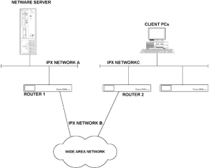
  The next periodic update we will examine is the SPX keep-alive. SPX is a connection-oriented protocol typically used by a network printer process (such as RPRINTER) or an application gateway (such as Novell's SAA gateway). To maintain an SPX connection during periods when no data is transmitted, both ends of an SPX connection transmit keep-alive messages every 3 seconds by default. (This is the NetWare 3.x default; NetWare 4.x sends SPX keep-alives every 6 seconds by default.) Keep-alive values on the server side cannot be user-configured, but they can be set on the client side, from a default of every 3 seconds up to one keep-alive every hour. An alternative to changing this default in the NetWare software is to implement SPX keep-alive spoofing on Cisco routers positioned between a client PC and NetWare server. Consider Fig. 5-4.  
   
  Figure 5-4: Network configuration for IPX/SPX spoofing  
  In this illustration, router 1 is spoofing onto IPX network A for the NetWare server and router 2 is spoofing onto IPX network C for the client PC SPX processes, and SPX keep-alives are kept off the WAN. SPX spoofing is implemented using the following global configuration commands:  
  Router1(config)#ipx spx-spoof  
  Router1(config)#ipx spx-idle-time 90  
  The first command enables SPX spoofing and the second command specifies the amount of time in seconds (90 in this case) before spoofing of keep-alive packets can occur.  
  Novell implements a 66-second unicast to all servers on the same internetwork to provide for comparison of license serialization numbers on servers in use. This is there to protect Novell from a user reinstalling the same software license on multiple servers on the same internetwork. If a serialization packet is detected that has the same license number as the server receiving the packet, a server copyright violation message is broadcast to all users and the NetWare server consoles. There are no specific commands to stop these packets within the Cisco IOS, and the only way to block these serialization packets traversing a WAN is to use an access list.  
  NetWare 4.1 Considerations.     The main administrative problem with NetWare 3 was that user accounts were defined on a per-server basis. In a LAN servicing several hundred or more users, several NetWare servers would have to be deployed and users would have to be given specific accounts on every NetWare server to which they needed access. This forced network managers to implement a maze of login commands to enable each user to get access to all the shared data needed.  
  To eliminate this problem, Novell introduced NetWare Directory Services (NDS), which replaced the flat-file user information database (the bindery) with a hierarchical, object-oriented replicated database. The advantage is that with the same database of user information on every server, a user can gain access to all resources needed with just one logon. With replication comes the problem of ensuring synchronization among these databases. To ensure synchronization, NetWare 4.1 timestamps each event with a unique code. (An event is a change to the database.) The timestamps are used to establish the correct order of events, set expiration dates, and record time values. NetWare 4.1 can define up to four different time servers:  
  1.   Reference time server passes the time derived from its own hardware clock to Secondary time servers and client PCs.  
  2.   Primary time server synchronizes network time with reference to at least one other Primary or Reference time server.  
  3.   Secondary time server receives the time from a Reference or Primary and passes it on to client PCs.  
  4.   Single-reference time server is used on networks with only one server and cannot coexist with Primary or Reference time servers. The Single-reference time server uses the time from its own hardware clock and passes it on to Secondary time servers and client PCs.  
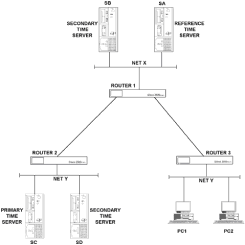
  This synchronization of time between servers across a network can add to network congestion and activate dial-on-demand links unnecessarily. Novell offers a TIMESYNC.NLM program that can be loaded on a NetWare 4.1 server to reduce the amount of time synchronization packet traffic. The best way to limit the amount of this type of traffic over WAN links is to locate time servers appropriately on the network (Fig. 5-5).  
   
  Figure 5-5: Locating NetWare time servers on an internetwork  
  In this internetwork, there is one Reference time server, SA. This will supply time synchronization to servers SB and SC. Server SC will, in turn, supply time synchronization to server SD. Because SC was made a Primary time server, it is the only server that needs to communicate with the Reference server on network Y.  
  Configuring EIGRP for IPX  
  We already have discussed how RIP in the IP world can provide less-than-optimal routing. The same is true of RIP in the world of IPX routing. If you are implementing IPX over a wide area network, you should consider making the WAN routing protocol EIGRP. EIGRP is more efficient and provides quicker network convergence time over router-to- router links than does IPX RIP. Because NetWare servers can only understand IPX RIP, however, we have the same issues in the Novell world as we did in the IP world when connecting Unix machines to an IGRP WAN.  
  We can make EIGRP the routing protocol for the WAN links, and use either static routes on the NetWare servers or redistribution on the routers, to enable the Novell servers to participate in routing across the WAN. To define IPX EIGRP on a Cisco router, enter the following commands:  
  Router1(config)#ipx router eigrp 22  
  Router1(config)#network aaa  
  The first line defines the IPX EIGRP routing process on the router to be part of autonomous system number 22. The second (and potentially subsequent lines defined) identifies the IPX network numbers directly connected to the router that will participate in the EIGRP route advertisements.  
  By default, EIGRP will redistribute IPX RIP routes into EIGRP as external routes and EIGRP routes into IPX RIP. An example of how to disable redistribution for IPX RIP updates into an EIGRP autonomous system is:  
  Router1(config)#ipx router eigrp 23  
  Router(config)#no redistribute rip  
  The operation of EIGRP is configurable and can be optimized to reduce WAN bandwidth utilization if necessary. The first step toward reducing EIGRP bandwidth utilization is to increase the interval between hello packets. If this value is increased, the hold time for that autonomous system also must be increased.  
  As previously stated, hello packets are sent by routers running EIGRP on a regular basis. These hello packets enable routers to learn dynamically of other routers on directly connected networks. In addition to learning about neighbors, the hello packets are used to identify a neighbor that has become unreachable. If a hello packet is not received from a neighbor within the hold time, the neighbor is assumed to have become unreachable. The hold time is normally set to three times the hello packet interval. To increase the hello packet interval and hold time, perform the following configuration commands:  
  Router1(config)#ipx hello-interval eigrp 22 15  
  Router1(config)#ipx hold-time eigrp 22 45  
  These commands executed on all routers within autonomous system 22 will increase the hello packet interval from the default 5 seconds to 15 seconds and the hold time from a default 15 seconds to 45 seconds.  
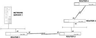
  In addition to the access list method of controlling SAP updates, EIGRP offers further opportunities to reduce the amount of WAN bandwidth consumed by SAP traffic. If an EIGRP neighbor is discovered on an interface, the router can be configured to send SAP updates either at a prespecified interval or only when changes occur. When no EIGRP neighbor is found on an interface, periodic SAPs are always sent. In Fig. 5-6, the default behavior of EIGRP for router 1 will be to use periodic SAPs on interface Ethernet 0, and send only SAP updates on Serial 0, when change to the SAP table occurs; this is an incremental update.  
   
  Figure 5-6: IPX EIGRP-based internetworks  
  This default behavior is fine for most instances; however, we can optimize the SAP traffic sent out the Ethernet 0 port of router 2 by changing the default behavior. We want to do this because the default behavior assumes that a NetWare server will be connected to any LAN interface on the router and therefore periodic updates are sent out. But in this case, the only device on the Ethernet 0 port of router 2 is an EIGRP router, which gives us the option to use incremental updates. The following commands will implement this change to default behavior for autonomous system 24 on Ethernet 0.  
  Router2(config)#interface E0  
  Router2(config-int)#ipx sap-incremental eigrp 24  
  The Basics of NLSP and IPXWAN Operation  
  An alternative to using EIGRP over WAN links is the new NLSP and IPXWAN protocols designed by Novell. The NetWare Link Services Protocol (NLSP) was introduced to address the limitations of the IPX RIP and SAP update processes, and is equivalent to using a link state protocol such as OSPF for IP routing instead of a distance vector protocol like IGRP. IPXWAN was designed to reduce the WAN bandwidth utilization of IPX routing, and is a connection startup protocol. Once the IPXWAN startup procedure has been completed, very little WAN bandwidth is utilized by IPX routing over the WAN link. NSLP will operate over IPXWAN wide area links, as will other protocols like RIP and SAP. IPXWAN does not require a specific IPX network number to be associated with the serial link; it will use an internal network number.  
  NLSP is derived from the OSI's link state protocol, IS-IS. The key difference between NLSP and other link state protocols is that it does not currently support the use of areas. An NLSP network is similar to having all router devices in area 0 of an OSPF autonomous system. Using a link state protocol requires each router to keep a complete topology map of the internetwork in its memory.  
  As changes in topology occur, routers detecting the change send link state advertisements to all routers. This initiates execution of the Dijkstra algorithm, which results in the recalculation of the topology database. Since these advertisements are sent out only when a failure of some kind occurs, as opposed to every 60 seconds as in the distance vector RIP, more efficient use of bandwidth results. The RIP/SAP routing method continues to be supported for linking different NLSP areas. Novell has stated that NLSP soon will be enhanced to support linking of separate NLSP areas directly together.  
     
  As with other link state routing protocols, NLSP routers must exchange hello packets on direct connections to determine who their neighbors are before exchanging route information. Once all the neighbors have been identified, each router sends a link state advertisement describing its immediate neighbors. After this, NLSP routers propagate network information via link state advertisements to other routers in the area. This process continues until routers become adjacent. When two routers are adjacent, they have the same topology database of the internetwork.  
  Once widespread adjacency is realized, the topology database is assumed correct if hello packets are continually received from all routers. Once three hello packets have been missed for a specific router, that router is assumed to be unreachable and the Dijkstra algorithm is run to adjust routing tables. Finally, a designated NLSP router on the internetwork periodically floods link state advertisements to all routers on the internetwork. This flood of packets includes sequence numbers of previous link state advertisements so that NLSP routers can verify they have the most recent and complete set of LSAs.  
  Before we consider specific router configurations for NLSP, we will look at the general operation of IPXWAN. Typically, NLSP and IPXWAN are implemented together, although they are not interdependent. One can be implemented without the other; NLSP does, however, require IPXWAN on serial links.  
  IPXWAN standardizes how IPX treats WAN links. IPXWAN can be implemented over the Point-to-Point Protocol (PPP), X.25, and frame relay. Before IPXWAN (a layer 3 protocol) can initiate, these layer 2 protocols must establish their WAN connection. Initialization of the layer 2 protocols starts a hello process to begin the IPXWAN process.  
  One of the routers will act as the primary requester, while the other acts as a slave that simply responds to these requests. The router having the higher internal network number value will be chosen as the primary requester. The two routers will agree on which routing protocol to use, typically RIP/SAP or NLSP, and then the requester proposes a network number to be assigned to the link. Finally the two routers agree on configuration details such as link delay and throughput available for the link.  
  Configuring NLSP and IPXWAN.     To set up IPXWAN and NLSP, a number of global and interface configuration commands must be executed. The prerequisites for implementing the global and interface commands for these protocols are as follows:  
    Global IPX routing must already be enabled before IPXWAN or NLSP commands will be accepted.  
    NLSP LAN interfaces must already have an IPX network number entry.  
    IPXWAN interfaces must have no IPX network number assigned.  
  The following input details the necessary global commands:  
  Router1(config)#ipx internal-network 8  
  Router1(config)#ipx router nlsp  
  Router1(config)#area-address 0 0  
  The first command defines the IPX internal network number that NLSP and IPXWAN will use to form adjacencies and to decide which router will be the primary requester. This number must be unique across the IPX internetwork. NLSP and IPXWAN will advertise and accept packets for this internal network number out of all interfaces, unless restricted by a distribute list. It is worth noting that the NLSP process adds a host address of 01 to this network number, which is a reachable address when using the ipx ping command. (IPX ping is not as useful as ICMP ping; not all NetWare devices support IPX ping.)  
  The second command line enables NLSP on the router and the third specifies the area address to use in the form of an address and mask. As NLSP supports only one area at the moment, zero values for both the area number and mask are adequate.  
  This completes global configuration. IPXWAN must be enabled for each serial interface, as must NLSP for each interface that is to participate in NLSP routing.  
  Let's now look at the interface configuration commands for IPXWAN.  
  Router1(config)#interface serial 0  
  Router1(config-int)#no ipx network  
  Router1(config-int)#ipx ipxwan  
  The first interface configuration command will not be reflected in the configuration file, and is input only as a safety measure to make sure that no network number is assigned to the link being used by the IPXWAN protocol. The second command simply enables the IPXWAN protocol. This second command can be followed by many option arguments, but the default option with no arguments normally is adequate. The configuration shown will use the Cisco default encapsulation for the layer 2 protocol, the Cisco-specific HDLC. If you want to change this to PPP, the encapsulation ppp interface command should be entered.  
  Optimizing NLSP.     Although NLSP and IPXWAN are considerably more efficient than the older RIP/SAP method of disseminating network information, some optimization of IPX and NLSP operation is possible.  
  RIP and SAP are enabled by default for every interface that has an IPX configuration, which means that these interfaces always respond to RIP and SAP requests. When NLSP is enabled on an interface, the router only sends RIP and SAP traffic if it hears of RIP updates or SAP advertisements. This behavior can be modified by the following interface configuration commands:  
    ipx nlsp rip off  stops the router from sending RIP updates out the specified interface.  
    ipx nlsp rip on  has the router always send RIP updates out this interface.  
    ipx nlsp rip auto  returns the interface to default behavior.  
    ipx nlsp sap off  stops the router from generating periodic SAP updates.  
    ipx nlsp sap on  has the router always generate periodic SAP updates for this interface.  
    ipx nlsp sap auto  returns the interface to default behavior.  
  When SAP/RIP is used, the maximum hop count permissible is 15 by default, which can be restrictive for large internetworks. The maximum hop count accepted from RIP update packets can be set to any value up to 254 (the example shows 50 hops) with the following command:  
  Router1(config)#ipx maximum-hops 50  
  The process we will go through to customize an NLSP setup is outlined as follows:  
    Configure the routers so that the least busy router is chosen as the designated router (DR).  
    Assign predetermined metric values to a link to directly influence route selection.  
    Lengthen the NLSP transmission and retransmission intervals to reduce NLSP network traffic.  
    Lengthen the link service advertisement intervals to reduce LSA bandwidth utilization.  
  On each LAN interface, NLSP selects a designated router in the same way as other link state protocols do. A DR generates routing information on behalf of all routers on the LAN to reduce protocol traffic on the LAN segment. If the DR were not there, each router on the LAN would have to send LSA information to all the other routers. The selection of a DR usually is automatic, but it can be influenced by router configuration commands.  
  Because the DR performs more work than other routers on the LAN, you might wish to ensure that either the least busy or most powerful router always is chosen as the DR. To ensure that a chosen router becomes the DR, increase its priority from the default of 44 to make it the system with the highest priority. To give a router a priority of 55, input the following commands. (This is for a router with its Ethernet 0 port connected to the LAN determining its DR.)  
  Router1(config)#interface E 0  
  Router1(config-int)#ipx nlsp priority 55  
  NLSP assigns a metric to a link that is based on the link throughput (similar to IGRP). No account of load is taken into consideration. If you want to manually influence the selection of routes, you can change the metric assigned to any link with the following command (the example shows a metric of 100):  
  Router1(config)#interface Serial 0  
  Router1(config-int)#ipx nlsp metric 100  
  The NLSP transmission and retransmission timers are adequate for just about every installation. If you feel the need to alter these parameters, however, the following commands show how to set the hello packet interval to 20 seconds and the LSA retransmission time to 60 seconds:  
  Router1(config)#interface E 0  
  Router1(config-int)#ipx nlsp hello-interval 20  
  Router1(config-int)#ipx nlsp retransmit-interval 60  
  Similarly, the intervals at which LSAs are sent out and the frequency of the Dijkstra (the Shortest Path First) algorithm execution normally are adequate. If your network contains links that are constantly changing state from up to down, however, these values can be modified as follows to an LSA interval of 20 seconds and minimum time between SPF calculation of 60 seconds:  
  Router1(config)#lsp-gen-interval 20  
  Router1(config)#spf-interval 60  
  If these values are changed, they should be uniform across an entire internetwork for efficient operation.  
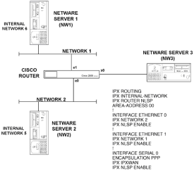
  Monitoring an NLSP/IPXWAN Internetwork.     Let's look at the pertinent configuration details of the Cisco router at the center of the internetwork shown in Fig. 5-7. This router is set up to run NLSP on all interfaces and IPXWAN on its serial link to NetWare server 3, as shown in the excerpt from its configuration file also in Fig. 5-7.  
   
  Figure 5-7: An NLSP- and IPXWAN-based internetwork  
  The global configuration entries enable IPX routing, set the internal IPX network number, and enable NLSP routing with the appropriate area address and mask. On each Ethernet interface, a network number is assigned and NLSP is enabled. It is assumed that the default Ethernet encapsulation type is used both by the router and the NetWare servers. The serial interface uses PPP for its encapsulation and is enabled for both IPXWAN and NLSP. The serial link has no IPX network number associated with it; it uses an unnumbered link by default.  
  The operation of IPXWAN can be monitored by the show ipx interface serial 0 command, which produces the output shown in Fig. 5-8.  
     
     
  router1>show ipx interface serial 0  
 
     
  Serial 0 is up, line protocol is up  
 
     
  IPX address is 0 0000.0010.000 [up] line-up RIPPQ: 0, SAPPQ: 0  
 
     
  Delay of this IPXnetwork, in tcks is 31 throughput 0 link delay  
 
     
  10/router1  
 
     
  0 IPXWAN delay (master owns):31  
 
     
  20 IPXWAN Retry limit:3  
 
     
  RIP Unnumbered  
 
     
  Slave: Connecty  
 
     
  State change reason: Received Router Info Req as xlave  
 
     
  Last received remote node info: 15/NW3  
 
     
  Client mode disabled, Static mode disabled, Error mode is reset  
 
     
  IPX SAP update interval is 1 minute  
 
     
  IPX type 20 propagation packet forwarding is disabled  
 
     
  Outgoing access list is not set  
 
     
  IPX Helper list is not set  
 
     
  SAP GNS procerssing enabled, delay 0 ms, output filter list is not set  
 
  Figure 5-8: The show ipx interface serial command 0 for an IPXWAN interface  
  The IPXWAN node number is defined by the internal IPX network number and the router's configured hostname, which in this instance is 10/Router1. The IPXWAN state indicates that it is a responder (slave), rather than a requester and is connected to a NetWare server named NW3, configured with an internal network number of 15.  
  To monitor the NLSP routes, issue the show ipx route command to view the IPX routing table, as shown in Fig. 5-9.  
     
     
  router1>show ipx route  
 
     
  Codes: C - connected primary network, c - connected secondary network  
 
     
  S - Static, F - Floating static, L - Local (internal), W - IPXWAN, R - RIP, E - EIGRP, N - NLSP, X - External, s - seconds, u - uses  
 
     
  4 total IPX routes. Up to 1 parallel paths and 16 hops allowed  
 
     
  No default route known  
 
     
  800(SAPE0  
 
     
  111(PPP)As1  
 
     
  5[20] [02/01] via3.0000.0210.98bc30sE0  
 
  Figure 5-9: Monitoring NLSP routes  
  This routing table labels the internal network number with an L indicator, the directly connected Ethernet networks with a C indicator, NLSP routes with an N indicator, and the IPXWAN network with a W indicator. These two commands give you all the information that is necessary to determine the state of NLSP and IPXWAN routing.  
  NetBIOS over IPX  
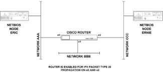
  The IPX packet type 20 is used to transport IPX NetBIOS packets through a network. NetBIOS was designed as a fast and efficient protocol for small individual networks. As such, NetBIOS does not use a network number when addressing a destination node; it is assumed that the destination is on the same network segment. NetBIOS implements a broadcast mechanism to communicate between nodes. Broadcasts normally are blocked by a router, so if we want broadcasts to traverse a router, we must specifically configure it to do so. In NetBIOS networking, nodes are addressed with a unique alphanumeric name. If two NetBIOS nodes need to communicate via a Cisco router, it is possible to configure the router to forward IPX packet type 20 broadcasts between specified networks. Figure 5-10 provides an example of this.  
  Suppose that in this network we want NetBIOS nodes Eric and Ernie to communicate. This means we have to enable IPX packet type 20 to traverse the router between network aaa and ccc. As no NetBIOS nodes are on network bbb, no type 20 packets need to be sent onto that network. The relevant parts of a router configuration are shown in Fig. 5-11.  
  The command that enables reception and forwarding of NetBIOS packets on an interface is the ipx type-20-propagation command configured for interfaces Ethernet 0 and Ethernet 2.
Bridging Nonroutable Protocols  
  Some networking systems, such as Digital Equipment's LAT (Local Area Transport) do not define network numbers in packets sent out on a network. If a packet does not have a specific destination network number, a router will assume that the packet is destined for the local segment and will not forward it to any other network. In most cases this is the right thing to do; there are some instances, however, in which two devices need to communicate using a nonroutable protocol, and a router stands between them. One option to enable these two machines to communicate is to use the bridging capability of Cisco routers.  
   
  Figure 5-10: Forwarding NetBIOS packets through a Cisco router  
     
  INTERFACE ETHERNET 0  
 
     
  IPX NETWORK AAA  
 
     
  IPX TYPE-20-PROPAGATION  
 
     
  INTERFACE ETHERNET 1  
 
     
  IPX NETWORK BBB  
 
     
  INTERFACE ETHERNET 2  
 
     
  IPX NETWORK CCC  
 
     
  IPX TYPE-20-PROPAGATION  
 
  Figure 5-11: Configuration for the router in Figure 5-10  
  Before we get into the specifics of using a Cisco router as a bridge, let's review the operation of the two types of bridge that have been widely implemented in the market, transparent bridges and source route bridges. What has ended up being available in the marketplace are bridges that typically do both transparent and source route bridging. A device acting as this type of bridge will act as a transparent bridge if the layer 2 header does not contain a Routing Information Field, and will act as a pure source routing bridge if there is a Routing Information Field. The following will discuss the operation of transparent and source route bridging separately.  
  Transparent Bridges  
  The transparent bridge was developed to allow protocols that were designed to operate on only a single LAN to work in a multi-LAN environment. Protocols of this type expect a packet to be received by the destination workstation to arrive unaltered by its progress through the LAN. The basic job of a transparent bridge, therefore, is to receive packets, store them, and retransmit them on other LANs connected to the bridge, making it useful for extending the limits of a LAN.  
  In a Token-Ring environment, a transparent bridge can increase the number of workstations on a ring. Each time a token gets passed from workstation to workstation on a ring, the clock signal degrades. A transparent bridge can be used to connect two physical rings and allow more workstations to be connected because it uses a different clock and token for each ring. As far as any layer 3 software is concerned, however, the two rings are still on the same network number.  
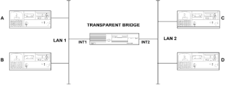
  A transparent bridge will do more than this, though, because a learning bridge will "learn" which MAC addresses of workstations are on which LAN cable and either forward or block packets according to a list of MAC addresses associated with interfaces kept in the bridge. Let's examine how the bridge operates in the multi-LAN environment of Fig. 5-12.  
   
  Figure 5-12: Transparent bridge operation  
  First it must be noted that as far as any layer 3 protocols, such as IP or IPX are concerned, LAN 1 and LAN 2 in this figure are the same network number. The process operated by the transparent bridge is as follows:  
    Listen to every packet on every interface.  
    For each packet heard, keep track of the packet's source MAC address and the interface from which it originated. This is referred to as a station cache.  
    Look at the destination field in the MAC header. If this address is not found in the station cache, forward the packet to all interfaces other than the one on which the packet was received. If the destination address is in the cache, forward the packet to only the interface the destination address is associated with. If the destination address is on the same interface as the device originating the packet, the packet is dropped; otherwise duplicate delivery of packets for that packet would result.  
    Keep track of the age of each entry in the station cache. An entry is deleted after a period of time if no packets are received with that address as the source address. This ensures that if a workstation is moved from one LAN to another, the "old" entry in the station cache associating that address with a now incorrect interface is deleted.  
  Using this logic, and assuming that workstations A, B, C, and D in Fig. 5-12 all communicate with one another, the bridge will produce a station cache that associates workstations A and B with interface 1, then C and D with interface 2. This potentially relieves congestion in a network. All traffic that originates at and is destined for LAN 1 will not be seen on LAN 2 and vice versa.  
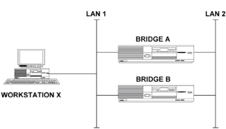
  This form of bridging works well for any LAN topology that does not include multiple paths between two LANs. We know that multiple paths between network segments is desirable to maintain connectivity if one path fails for one reason or another. Let's look at what a simple transparent bridge would do if implemented in a LAN environment such as that shown in Fig. 5-13.  
   
  Figure 5-13: Network with multiple bridge paths between LANs  
  Let's say this network is starting up and the station cache for both bridge A and B are empty. Suppose a workstation on LAN 1 let it be termed "workstation X" wants to send a packet. Bridges A and B will receive this packet, note that workstation X is on LAN 1, and queue the packet for transmission onto LAN 2. Either bridge A or bridge B will be the first to transmit the packet onto LAN 2; for argument's sake, say bridge A is first. This causes bridge B to receive the packet with workstation X as the source address on LAN 2, since a transparent bridge transmits a packet without altering header information. Bridge B will note that workstation X is on LAN 2 and will forward the packet to LAN 1. Bridge A will then resend the packet to LAN 2. You can see that this ends up a nasty mess.  
  Because a routed network typically will have multiple paths between LANs, turning on bridging capability could be as disastrous as in the example above if it were not for the spanning tree algorithm implemented on Cisco routers.  
  The Spanning Tree Algorithm.     The spanning tree algorithm exists to allow bridges to function properly in an environment having multiple paths between LANs. The bridges dynamically select a subset of the LAN interconnections that provides a loop-free path from any LAN to any other LAN. In essence, the bridge will select which interfaces will forward packets and which will not. Interfaces that will forward packets are considered to be part of the spanning tree. To achieve this, each bridge sends out a configuration bridge protocol data unit (BPDU). The configuration BPDU contains enough information to enable all bridges to collectively:  
    Select a single bridge that will act as the "root" of the spanning tree.  
    Calculate the distance of the shortest path from itself to the root bridge.  
    Designate, for each LAN segment, one of the bridges as the one "closest" to the root. That bridge will handle all communication from that LAN to the root bridge.  
    Let each bridge choose one of its interfaces as its root interface, which will gives the best path to the root bridge.  
    Allow each bridge to mark the root interface and any other interfaces on it that have been elected as designated bridges for the LAN to which it is connected as being included in the spanning tree.  
  Packets will then be forwarded to and from interfaces included in the spanning tree. Packets received from interfaces not in the spanning tree are discarded and packets are never forwarded onto interfaces that are not part of the spanning tree.  
  Configuring Transparent Bridging.     When configuring a Cisco router to act as a transparent bridge, you need to decide the following before entering any configuration commands into the router:  
    Which interfaces are going to participate in bridging and what the bridge group number for these interfaces will be.  
    Which spanning tree protocol to use.  
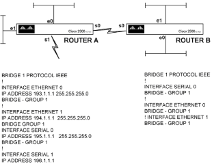
  In Fig. 5-14 we have a router with four interfaces, three of which belong to bridge group 1. If the router had more interfaces, and if a second group of interfaces were chosen to form a bridge group, the two bridge groups would not be able to pass traffic between them; in effect, different bridge groups act as different bridges and do not pass configuration BPDUs between them. In the example of Fig. 5-14, IP traffic is routed between the interfaces and all other protocols are bridged.  
  In the configuration of the router in Fig. 5-14, the bridge protocol command defines the spanning tree algorithm to use; for transparent bridging that is either IEEE or DEC. This value must be consistent between all routers forming part of the same spanning tree. The group number is a decimal number from 1-9 that identifies the set of bridged interfaces. This configuration command option is implemented in case you want to set up on the same router sets of interfaces that belong to different bridging groups.  
   
  Figure 5-14: Network and router configuration for basic transparent bridging  
  In Fig. 5-14, router A has been configured for Ethernet 0, Ethernet 1, and Serial 0 to be part of bridge group 1. This bridge group number has significance only within router A, where it identifies the interfaces that will participate in bridging on that router. Router B has bridge group 1 defined as well. Again, this has relevance only within router B. Packets could just as well be bridged between routers A and B if the Serial 0, Ethernet 0, and Ethernet 1 interfaces on router B were made part of bridge group 2.  
  Extending transparent bridging to include dozens of Cisco routers is a simple matter, as the same configuration given here is replicated on each router to be included in the spanning tree. As long as each router to be included in the spanning tree has an interface that is configured to bridge transparently, and is connected to an interface on another router that is configured to bridge transparently, all such routers will be included in the spanning tree.  
  Source Routing Bridges  
  Source routing at one time competed with transparent bridging to become the 802.1 standard for connecting LANs at the layer 2 level.  
  When spanning tree bridges became the preferred 802.1 standard, source routing was taken before the 802.5 committee and was adopted as a standard for Token-Ring LANs. As such, it is only really used when connecting Token-Ring LANs.  
  The idea behind source routing is that each workstation will maintain in its memory a list of how to reach every other workstation; let's call this the route cache. When a workstation needs to send a packet, it will reference this route cache and insert route information in the layer 2 header of the packet, telling the packet the exact route to take to reach the destination. This route information is in the form of a sequence of LAN and bridge numbers that must be traversed in the sequence specified in order to reach the destination.  
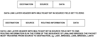
  Let's look at Fig. 5-15, which shows the regular layer 2 header and one that is modified to participate in source route bridging. To inform a receiving node that the packet has source route information rather than user data after the source address, the multicast bit in the source address is set to 1. Prior to source route bridging, this multicast bit was never used.  
   
  Figure 5-15: Layer 2 headers with and without the source multicast bit set  
  If a workstation needs to send a packet to a destination not currently in the route cache, this workstation will send out an explorer packet addressed to that destination. An explorer packet traverses every LAN segment in the network. When an explorer packet reaches a bridge on its travels and could travel one of many ways, the bridge replicates the explorer packet onto every LAN segment attached to that bridge. Each explorer packet keeps a log of LANs and bridges through which it passes.  
  Ultimately the destination workstation will receive many explorer packets from the originating workstation and will, by some mechanism, tell the originating workstation the best route to enter into the route cache. Whether the destination or originating workstation actually calculates the route information, and what the exact details of the best route are, is open to vendor implementation and not specified in the standards.  
  Configuring Source Route Bridging.     The first difference between transparent bridging and source route bridging becomes apparent when we look at the configuration commands. In transparent bridging, it was necessary only to identify the interfaces on each router that were to participate in transparent bridging and the spanning tree algorithm would work out which interfaces on each router in the spanning tree would be used for forwarding packets. Source route bridging is not so simple and requires every LAN and every source route bridge to be uniquely identified in the network. Configuration of a Cisco router for source route bridging is simple if we consider a bridge that has only two interfaces configured for source route bridging, as shown in Fig. 5-16. This then becomes a matter of bridging between pairs of Token-Ring LANs.  
   
  Figure 5-16: A simple source route bridge network  
  The following commands configure the Token-Ring 0 and Token-Ring 1 ports for source route bridging.  
  Router1(config)#interface to 0  
  Router1(config-int)#source-bridge 10 2 11  
  Router1(config-int)#interface to 1  
  Router1(config-int)#source-bridge 11 2 10  
  The first source bridge configuration command arguments for the Token-Ring 0 interface can be explained as follows:  
    The local ring number for interface Token-Ring 0 is in this case 10, but it can be a decimal number between 1 and 4095. This number uniquely identifies the ring on that interface within the bridged network.  
    The bridge number, which must be between 1 and 15, is in this case 2, and it uniquely identifies the bridge connecting the two rings within the bridged network.  
    The target ring, which is the network number of the second ring in the ring pair, must be between 1 and 4095, and in this case is 11.  
  The second source bridge command is for the Token-Ring 1 port and merely reverses what this interface sees as the local and destination ring.  
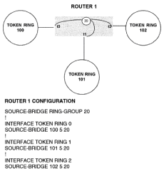
  If a bridge has more than two interfaces that need source route bridging, an internal virtual ring needs to be defined and each "real" interface is bridged to the virtual ring. This configuration is shown in Fig. 5-17, with each external ring (100, 101, and 102) individually bridged to the internal ring 20, via router 1, which is identified with a source route bridging number of 5. ("Router 1" is the configured hostname of the router.)  
   
  Figure 5-17: A source route bridging for more than two LANs  
  It is worth noting that source route bridging has significance only on Token-Ring interfaces. If you are using a Cisco access server to provide remote dial-up services to a Token-Ring LAN, the dial-up ports will not use a Token-Ring encapsulation; they will probably use PPP. Network administrators may be forgiven for thinking that since all workstations on a LAN must have source routing enabled to get access to servers on remote rings, the dial-up workstations would need this too. This is, in fact, not the case. As the dial-up workstations are using PPP as a layer 2 protocol, there is no place to insert source route information in the layer 2 header.  
  Source Route Transparent Bridging  
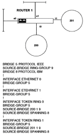
  What is implemented in the main is source route transparent bridging, in which a bridge will use source routing information if the multicast bit in the source address is set to 1 (this bit is now known as the Routing Information Indicator), and transparent bridging if the Routing Information Indicator is not set. Figure 5-18 shows a bridged network with a router configuration for both source route and transparent bridging.  
  The tasks to be accomplished when configuring a router to perform both transparent and source route bridging are as follows:  
    For transparent bridging on Ethernet interfaces, define a transparent bridge process and associate a number with it.  
    Define which spanning tree algorithm will be used by the Ethernet ports.  
   
  Figure 5-18: Router configuration for source route transparent bridging  
    Define an internal ring that can be paired with all external token rings.  
    Define the automatic spanning tree function for the source route network. Note that the interfaces in a source route network can transparently bridge packets. The interfaces in a source route network will, however, define a separate spanning tree from the transparent bridge interfaces in the Ethernet network.  
    Associate each Ethernet port with a specific bridge group.  
    Enable the spanning tree function for each interface to be part of the source-route-based spanning tree.  
    Associate each Ethernet and Token-Ring port with a transparent bridge group.  
  It seems complicated and it is. I do not mind admitting that I do not like bridging, and I think that source route bridging does not scale well in a network of any size. Most people these days will use a layer 3 protocol (either IP or IPX), so there is little need to try to muscle layer 3 functionality into a layer 2 protocol. Having said that, if you really do have to implement source route transparent bridging and need to understand the commands shown in Fig. 5-18, an explanation follows.  
  The bridge 5 protocol ieee command defines a transparent bridge process with ID 5. This command partners with the interface command bridge-group 5 that identifies all the interfaces to be part of this transparent bridge group. The source-bridge ring- group 9 command defines the internal virtual ring with which all external rings will be paired. The bridge 8 protocol ibm command defines the spanning tree algorithm for this router and associates it with an ID of 8. This command partners with the interface command source-bridge spanning 8 that identifies all Token-Ring ports that will participate in defining the spanning tree for the Token-Ring side of the network. The final command is the source-bridge 200 1 9 command, which gives this bridge a source route bridging ID of 1 and links the Token-Ring network number on the specific interface (in this case 200) to the internal virtual token ring (number 9).
IBM Networking  
  IBM networking is a topic vast enough to justify the writing of many, many volumes. Here we have only one section in a chapter to give an overview of the most common things a network administrator will have to do when integrating IBM applications over a TCP/IP-based Cisco router network. Typically, Cisco routers are implemented to reduce or totally eliminate the need for IBM front-end processors (FEPs). FEPs direct SNA traffic over a network, typically using low-speed 9600 bps lines. The drive to reduce FEP utilization comes from an economic need to reduce the cost of FEP support and to provide a cost-effective WAN that can deliver client/server IP-based, as well as SNA, applications.  
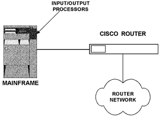
  Typically Cisco routers get introduced in an IBM data center via direct channel attachment to replace a FEP and in each remote branch location connected to the data center. The data center router will route IP traffic over the WAN as normal and use a technology called Data Link Switching to transport SNA or NetBIOS traffic over the same WAN. At the remote branch end of the network, a small 2500-series router can be used both to connect LAN workstations to the WAN that can receive IP traffic, and to connect an IBM terminal controller that receives SNA traffic to service local IBM 3270 terminals.  
  Overview of IBM Technology  
  Let's face it, all this TCP/IP internetworking stuff may be fun, but what really delivers the benefits of computer technology to an organization is a well-designed, reliable, and responsive application. IBM technology has been the technology of choice for mission-critical applications for the past 20 years and will be with us for many more. The basic reason for this is that it works. With IBM's NetView management system, network managers also have an effective tool to monitor, troubleshoot, and (important for mission-critical applications), guarantee response times of applications.  
  IBM technology is hierarchical and fits well into an organization that works in a structured fashion, as everything is controlled by a central MIS department. Clearly, in today's faster-moving business environment, such central control with its inherent backlogs is not the favored approach for many organizations when planning future information systems development. Having said that, if an existing application is in place and serving its users well, there is little need to replace it just to make a network manager's life easier. Given that IBM applications will be around for a while, it is more cost-effective to integrate them into a multiprotocol network than to provide a separate network just for that traffic. Let's now look at IBM's communication technology in a little more detail.  
  IBM Networking Systems.     The most prevalent IBM networking system is the Systems Network Architecture (SNA). SNA is a centralized hierarchical networking model that assigns specific roles to machines within the overall network. IBM mainframe operating systems (such as MVS, VM, or VSE) were designed to have access to an SNA network via VTAM, the Virtual Telecommunications Access Method, which defines which computers will connect to which applications. Applications in this environment are written to interface to VTAM through Logical Unit (LU) sessions. LU sessions are established, terminated, and controlled via a VTAM function called the System Services Control Point (SSCP). For IBM network staff, the terms LU and PU (Physical Unit) are frequently referenced terms. Defining an LU of 2 identifies a 3270 terminal session, for example. In addition, each type of terminating device (such as a printer or workstation) will have a different PU number associated with it.  
  IBM networkers are accustomed to having a method by which to allocate specific bandwidth resources to different types of traffic. This is not available as standard within TCP/IP, which relies on vendor-specific features such as Cisco's priority or custom queuing to duplicate that functionality. Being a centralized hierarchy, SNA provides good security with the RACF system, which is not matched very well by any security system currently implemented in the TCP/IP world. Again, TCP/IP standards rely on vendor-specific implementations such as Cisco access lists and TACACS+ (all of these extensions will be covered in subsequent sections).  
  A totally different IBM architecture is the Advanced Peer-to-Peer Networking scheme (APPN), which was designed for the AS/400 environment. In this architecture, the Logical Unit used is LU6.2, which applications use via a program interface called Advanced Program-to-Program Communication (APPC). Instead of 3270 sessions, the AS/400 operating system uses 5250 sessions to communicate between the server and workstation. A large part of why IBM systems lost popularity was due to these different architectures associated with different hardware platforms. In many organizations, network staff had to implement multiple cabling systems and users needed multiple terminals on their desks to access different IBM systems.  
  TCP/IP Support Provided by IBM.     IBM mainframe and midrange computers will support TCP/IP connectivity directly via the TN3270 and TN5250 protocols. These protocols allow a user workstation running only TCP/IP communications software to run 3270 and 5250 applications over a TCP/IP network. Most of the functionality required by a user to run IBM applications is provided by the TN3270 and TN5250 protocols; however, some features are missing that might be important to some users.  
  In TN3270, the print job confirmation feature, important to users such as stockbrokers looking for trade confirmations, is not supported by the TCP/IP LPR/LPD printing mechanism. Also, the SysReq and Attn keys used to swap between mainframe applications is not fully supported under TCP/IP.  
  In TN5250, most terminal emulation, printing, and file-sharing functions are available, but file transfer has been a problem. APPN allows sophisticated querying of DB2 databases to retrieve data. With TN5250, there are no APPN functions, so it is much more difficult to retrieve query output from a DB2 database.  
  IBM has resolved these problems with a technology called Multiprotocol Transport Networking (MPTN). Using this technology, an APPC application can communicate over a TCP/IP network without the need for client workstations to load multiple protocol stacks. IBM achieves this by use of an application call translator that maps APPN to TCP/IP sockets function calls.  
  With an introduction to the IBM technology and an idea of some of the problems, let's look at how Cisco deals with them.  
  Cisco's Approach to IBM Technology Integration  
     
  If you decide to integrate IBM technology onto a multiprotocol network, the biggest concern of those responsible for delivering IBM application support is that they will lose the ability to guarantee response times. Typically, SNA applications have predictable low bandwidth consumption, whereas TCP/IP protocols are typified by bursts of traffic, often generating a need for high bandwidth availability. To alleviate these fears, Cisco implemented priority output queuing, which enables network administrators to prioritize traffic based upon protocol, message size, physical interface, or SNA device. If this mechanism is deemed inadequate, Cisco's custom queuing allows specific bandwidth to be allocated to different types of traffic, in effect providing separate channels on the one link for the different types of traffic carried.  
  Direct Channel Attachment.     Let's take an overview of channel attachment, as shown in Fig. 5-19. In an IBM mainframe, Input/Output Processors (IOPs) communicate between the main CPU and the mainframe channel, which is an intelligent processor that handles communication with external devices. The Cisco Channel Interface Processor (CIP) can connect directly to a mainframe channel for high-speed communication between a mainframe and a router network. A CIP in a Cisco router replaces the need for an IBM 3172 controller to provide communication for terminal and printer devices. Channel attachment technologies that Cisco supports for CIP implementation are as follows:  
    ESCON, a fiber optic link between an ES/9000 mainframe channel and the CIP.  
    Parallel bus-and-tag for connecting to System 370 and subsequent mainframes.  
    Common Link Access for Workstation (CLAW), which enables the CIP to provide the functionality of a 3172 controller.  
   
  Figure 5-19: Connecting a mainframe and router via channel attachment  
  The CIP works in conjunction with an appropriate interface adapter card, the ESCON Channel Adapter (ECA) for fiber connection, or the bus-and-tag Parallel Channel Adapter (PCA). One CIP supports two interface cards and up to 240 devices. When installed in a Cisco router, the CIP can be configured much like any other interface. The CIP will use TCP/IP to communicate with the mainframe channel, so the mainframe needs to be running TCP/IP. If the mainframe has VM for an operating system, it must be running IBM TCP/IP for VM version 2, release 2; if it is running MVS, it must support IBM TCP/IP for MVS version 2, release 2.1.  
  To get the CIP up and working, a compatible configuration must be entered into the CIP interface and the IBM channel. Before we look at those configurations, it should be noted that the CIP can be installed only in a modular Cisco router. The modular series routers (the 4x00- and 7x00-series) are supplied as a chassis in which modules with different interfaces can be installed. The 2500-series routers come with a fixed configuration and have no slots for additional cards to be installed. So far, configurations given for routers have assumed a 2500-series router.  
  To configure an interface for a modular router, we first need to specify the slot number of the card. For example, if we have a four-interface Ethernet module inserted in the slot 0 of a 4700 router, the Ethernet interfaces will be addressed as Ethernet 0/1, Ethernet 0/2, Ethernet 0/3, and Ethernet 0/4. All show and interface configuration commands must reference the specific slot and Ethernet interface in this way. The same is true of a CIP card. The following shows how to select port 1 of a CIP interface card in slot 0:  
  Router1(config)#interface channel 0/1  
  Router1(config-int)#  
  Now that the router is in configuration mode for the CIP interface connected to the IBM channel, a basic configuration can be input to establish IP communication between the IBM channel and the CIP. The configuration commands to define a router process, and assign an IP address and CLAW parameters are shown as follows:  
  router eigrp 30  
  network 172.8.0.0  
  network 173.2.0.0  
  !  
  interface channel 0/1  
  ip address 172.8.5.1 255.255.255.0  
  claw 01 0 173.2.6.4 MVSM/C D100 tcpip tcpip  
  The CLAW parameters are not obvious and should be configured with help from a Cisco Systems engineer. Essentially, the CLAW arguments can be defined as follows:  
    The 01 is the path that is a value between 01 and FF, which is always 01 for an ESCON connection.  
    The next 0 value is a device address from the UNITADD value in the host IOCP file and should be obtained from the IBM host administrator.  
    The rest of the values are derived from the Device, Home, and Link values from the host TCP/IP configuration files and refer to the host IP address, host name, device name, and host and device applications.  
  Once operational, the CIP can be monitored and controlled much the same as any other interface on a Cisco router. All the usual show interface, show controller, and shutdown/no shutdown commands work in the same fashion as for Ethernet or serial interfaces.  
  STUN and DLSw.     Cisco's Serial Tunnel (STUN) feature was designed to allow IBM FEP machines to communicate with each other over an IP network. STUN encapsulates the SDLC frames used to communicate between FEPs within an IP packet for transmission over an IP internetwork. This provides flexibility in internetwork design and enables SNA and IP traffic to share the same wide area links, reducing costs and simplifying management. DLSw, which stands for Data Link Switching, provides a method for encapsulating IBM layer 2 LAN protocols within IP packets.  
  Using STUN to Interconnect FEP Machines.     The most popular implementation of STUN provides local acknowledgment between the router and the FEP, to keep this traffic off the WAN. This does, however, require knowledge of the Network Control Program (NCP) SDLC addressing scheme setup in the connected FEP. Figure 5-20 shows how FEPs are connected with and without STUN-enabled routers between them.  
  As you can see, the Serial 0 port on both router 1 and router 2 takes the place of a modem that previously connected to the FEP. This means that the FEP is expecting to connect to a DCE device. Therefore the router-to-FEP cable must have the configuration that sets the router port as a DCE, and we must enter a clockrate command in the configuration of interface Serial 0, just as we did in the original lab setup in Chap. 3 when we were connecting two router ports directly together.  
  Before we see the configurations for router 1 and router 2, let's discuss what we need to achieve with the configuration.  
   
  Figure 5-20: Connecting STUN-enabled routers between IBM FEPs  
  STUN-enabled routers communicate on a peer-to-peer basis and we need some way of identifying each router to its STUN peer or peers. This is achieved by defining a peer name for each router. The peer name is defined as one of the IP addresses of an interface on that router. Typically a loopback interface is defined, and the address of the loopback interface is used as the router peer name. The reason for this is that loopback addresses are up only as long as the router is up; if we gave the router a peer name of one of the serial interfaces, the peer name would become invalid if the serial interface was down for any reason.  
  Next, all the STUN peers that need to communicate as a group must be assigned the same STUN protocol group number. STUN peers will not exchange information with peers in another group number. The stun protocol-group command also defines the type of STUN operation for the link. The most popular option is the SDLC option, which provides local acknowledgment to the FEP and keeps this traffic off the serial link. The other popular option is the basic option of this command, which does not provide local acknowledgment, but does simplify router configuration slightly.  
  Using the SDLC option of the stun protocol-group command necessitates configuring the serial port connected to the FEP with an appropriate SDLC address number, which should be provided by the IBM FEP administrator. This option provides local acknowledgment of link-level packets, and therefore reduces WAN traffic. Once the SDLC address has been defined, we need to use the stun route address x interface serial y command, where x is the SDLC address number and y is the serial port through which you wish to direct STUN-encapsulated FEP frames. A stun route address ff interface serial y command directs broadcast SDLC traffic through the same STUN-enabled interface.  
  A typical STUN configuration for router 1 and router 2 in Fig. 5-20 is shown in Fig. 5-21.  
   
  Figure 5-21: Router 1 and router 2 configuration from Figure 5-20  
     
    Bridge hop-count limit of 7.  
    Excessive generation of broadcast explorer packets, consuming WAN bandwidth.  
    Unwanted timeouts at the Data Link level over WAN links.  
  It is important to realize that DLSw is not a layer 3 protocol and therefore does not perform routing. DLSw is a layer 2 protocol and works on the basis of establishing a DLSw circuit between two routers in an IP network. When DLSw is implemented, local Data Link level (layer 2) communications are terminated at the local router, enabling that router to provide link-level acknowledgments. This functionality effectively turns a connection between two machines communicating via a DLSw router pair into three sections. At each end of the link, the machines will establish a connection with the DLSw router (typically a source route connection), and the two DLSw routers will establish TCP connections to carry the traffic over the IP WAN. In Fig. 5-22, PC A exchanges link-level acknowledgments with router 1, and PC B exchanges link-level acknowledgments with router 2; router 1 and router 2 exchange DLSw information via TCP connections.  
   
  Figure 5-22: The three links used to establish a DLSw connection over an IP network  
  In fact, before it is possible to switch SNA or NetBIOS traffic between two DLSw-enabled routers, these routers must establish two TCP connections. Once the TCP connections are established, various data will be exchanged between the routers, the most noteworthy of which are the MAC addresses and NetBIOS names each router can reach. So how does DLSw direct traffic through an IP network?  
  The process is essentially the same for both SNA and NetBIOS switching. Both protocols will seek out the location of a destination by some type of explorer packet sent out on the network. The explorer packet asks all devices if they can get to the desired destination. One of the DLSw routers on the IP network should respond that it can reach the destination, at which time the TCP connections between the routers are made, and the packet can be sent from source to destination over the IP WAN.  
  There are many permutations and combinations of possible interconnects that might need to be made via DLSw links. We shall examine the example of connecting a remote Token-Ring LAN to a central SDLC IBM controller here, and in the next section on Windows NT, we will look at the example of connecting two Ethernet segments together via DLSw, so that NetBEUI traffic can be switched over an IP WAN.  
  The example shown in Fig. 5-23 is of a DLSw implementation that connects an SDLC controller to a remote Token-Ring LAN via an IP WAN.  
   
  Figure 5-23: Using DLSw to connect an SDLC controller to a remote token ring  
  Let's discuss the configuration commands implemented one by one.  
  Command source-bridge ring-group 1000 defines a DLSw router group. Routers will establish DLSw connections only with other routers in the same ring group.  
    Command dlsw local-peer peer-id 180.4.1.1 enables DLSw on the router and gives the router a DLSw ID, which is taken from the loopback address defined, just as was done for STUN in the previous section.  
    Command dlsw remote-peer 1000 tcp 180.4.3.2 identifies a remote peer with which to exchange DLSw information using TCP. In this command, the 1000 value is the ring-group number and must match that set by the source-bridge ring-group command.  
    Command sdlc vmac 1234.3174.0000 sets a MAC address for the serial port connecting to the SDLC controller. This is a necessary part of enabling the link-level addressing for DLSw, enabling complete source-to-destination addressing using link-level addresses.  
    Command sdlc role primary sets this end of the link as the primary.  
    In command sdlc xid 06 12345, XID requests and responses are exchanged prior to a link between the router and the controller reaching an up state. The XID is derived from parameters set in VTAM and must be determined by the IBM administrator.  
    Command sdlc partner 1234.5678.9abc 06 defines the MAC address of the token ring on the remote router that will be communicated with, and the SDLC ID number of the link connecting the two DLSw routers together.  
    Command sdlc dlsw 5 associates the DLSw and SDLC processes, so that DLSw will switch SDLC ID 5 traffic.  
    Command source-bridge 5 4 1000 enables source routing for the token ring attached to router 2 and defines the token ring as ring number 5, router 2 as bridge number 4, and the destination ring as number 1000.  
    Command bridge 8 protocol ibm defines the spanning tree algorithm for this router and associates it with an ID of 8.  
    Command source-bridge spanning 8 identifies all the Token-Ring ports that will participate in defining the spanning tree for the Token-Ring side of the network.  
  As you can see, this type of configuration is not trivial and takes significant cooperation between IBM data center staff and those responsible for Cisco router management.
Networking Windows NT  
  Windows NT has the fastest-growing market share of any network operating system (NOS) currently in the market. It seems that Microsoft has finally produced a NOS with which to challenge the leadership position of Novell's NetWare. NT bases much of its LAN communication on NetBEUI, the NetBIOS Extended User Interface, which is a legacy from Microsoft's LAN Manager and IBM's PC LAN products. NT, however, has built into the operating system the ability to interface to IPX/SPX, TCP/IP, and DLC (Data Link Control).  
  I will not go into the details of setting up these protocols using Windows NT utilities; there are plenty of Microsoft manuals and Microsoft Press publications to do that for you. What will be covered here is an overview of what NT servers use to communicate network information, and what the options and issues are for interconnecting NT servers and workstations over a WAN.  
  Windows NT Network Protocols  
  In this section we will examine the transport protocols of Windows NT, which are NetBEUI, NWLink, TCP/IP, and DLC.  
  NetBEUI.     NetBEUI originally was designed for small LANs of around 20 to 100 workstations. As such, it was not designed with any concept of network numbers and is therefore a nonroutable protocol. Windows implements NetBEUI 3.0, which uses the NetBEUI Frame (NBF) protocol that is based on the NetBIOS frame type and therefore is compatible with previous versions of NetBEUI.  
  In communications based on NetBIOS, computers are referred to by name rather than address. Packets on the local segment are still delivered by MAC address, with each station on the network maintaining a computer-name-to-MAC-address translation. On a single LAN segment, NetBIOS communications deliver better performance than a routable protocol because the communication process is simpler. These days, however, there are very few networks installed that only ever need to connect to fewer then 100 other computers. Recognizing the problems of NetBEUI in larger environments, Microsoft chose TCP/IP as its strategic WAN protocol for Windows NT implementations.  
  NWLink.     NWLink is the native Windows NT protocol for Novell's IPX/SPX protocol suite. NWLink provides the same functionality that IPX.COM or IPXODI.COM files did for a machine using the Open Data Link Interface (ODI) specification, namely the ability to use IPX as a transport protocol. To connect to a NetWare server requires the use of VLM programs for an ODI machine, or the Client Services for NetWare (CSNW) redirector for Windows NT.  
  NWLink is useful if you have a mixed environment of NT and NetWare servers and need an NT machine to communicate with both.  
  TCP/IP.     In the Windows NT world, TCP/IP is used as a transport protocol, primarily for WAN connections. Later in this section we will be discussing functions of the NT server that generate network traffic, most of which can be encapsulated within TCP/IP. This is useful for minimizing the number of protocols that need to be supported on the WAN, but can be an issue if the encapsulated NetBEUI traffic starts to reach significant levels. We will discuss this later.  
  The NT implementation for TCP/IP includes SNMP and DHCP support, as well as the Windows Internet Name Service (WINS), which maintains a central database of computer-name-to-IP-address translations. NetBT, which stands for NetBIOS over TCP/IP, also is supported by NT for NetBIOS communication with remote machines via encapsulation in TCP/IP.  
  Data Link Control.     An important difference between DLC and the other protocols supported by Windows NT is that DLC is not meant to be used as a primary means of workstation-to-server communication. That's because DLC does not have a NetBIOS interface. Even when other protocols such as TCP/IP are used for workstation-to-server communications, a NetBIOS interface is needed to encapsulate NetBIOS traffic within this other protocol, just as NT computers need to pass NetBEUI among themselves to function.  
  The DLC protocol needs to be implemented only on machines that either access IBM mainframes using certain emulation packages, or print to some older types of Hewlett-Packard printers.  
  Windows NT Network Traffic  
  In the world of NetWare servers, we saw that SAP advertisements primarily, and RIP updates secondly, are the means by which the NOS itself steals available bandwidth from the applications we wish to run over our internetwork. SAP and RIP were designed to advertise servers, available services, and the means to get to those services. In the world of Windows NT, there is the browser service that performs an equivalent function.  
  In our discussion of optimizing NetWare protocols for transmission over WANs, we saw that the Cisco IOS had many options for directly controlling the propagation of IPX SAP and RIP packets, because IPX is a routable protocol. Because the Windows NT browser service is based on NetBEUI transport, which is not routable, there is no opportunity for such a fine degree of control over the propagation of these packets by the Cisco IOS. We will, however, discuss the options for maintaining browser service over WAN links.  
  Windows NT Browser Service Overview.     The Windows NT browser service is available to enable the sharing of resources across the network. This is achieved by the election of  master and backup browser servers on each network segment. The browser servers keep track of shareable services on the network, and client computers query the browser servers to see what is available. The types of network traffic that this process generates are illustrated as follows.  
    Each potential browser will advertise its candidacy via browser election packets, and an election process will take place to determine which machines become primary or backup servers.  
    The master browser sends to backup browsers a new list of servers every 15 minutes.  
    Nonbrowsers, potential browsers, and backup browsers announce their presence every 1 to 12 minutes.  
    Workstations retrieve shareable resource information from their backup browsers on an as-needed basis.  
  Let's examine these concepts a little more closely.  
  Browser Types.     A browser is a computer that holds information about services on the network, file servers, printers, shared directories, etc. The job of providing a browser service to nonbrowser machines is spread among several computers on a network, as defined in the following:  
    Master browser maintains a list of all available network services and distributes the list to backup browsers. No client machine requests information directly of the master browser; client machines only request information directly from backup browsers. For each Windows NT workgroup or domain defined, there is only one master browser per Windows NT Workgroup or Domain.  
    Backup browsers receive a copy of the browser list from the master browser and send it to client computers as requested.  
    Potential browser is a computer that could be a browser if so instructed by the master browser.  
  An election process takes place to determine which computer will become the master browser and which computers will become backup browsers. An election is forced if a client computer or backup browser cannot locate a master browser, or when a computer configured to be a preferred master browser is powered on. The election is initiated by the broadcasting of an election packet to all machines on that network. The election process ensures that only one computer becomes the master browser; the selection is based on the type and version of the operating system each machine is running.  
  Browser Traffic.     Assuming that browser election has taken place and the master browser and backups are operational, we can describe the traffic generated by the browser as follows.  
  After the initial boot sequence, a computer running the server process (workstations can run this process in addition to NT servers), will announce its presence to its domain's master browser. This computer is then added to the master browser's list of network services available. The first time a client computer wants to locate a network resource, it will contact the master browser for a list of backup browsers, and requests the list of network resources (domains, servers, etc.) from a backup server. The client computer now has what it needs to view, select, and attach to the available network resources.  
  The client PC now has a list of available resources. What happens if one of those resources becomes unavailable? There are browser announcements going on continually on a network. These announcements are similar in concept to routing update advertisements, i.e., as long as a router continually advertises route updates, it will still be considered usable by the other routers. Similarly, as long as a browser or server announces itself periodically, it will be considered available; if it stops announcing itself, however, it is deleted from the network resource list.  
  Initially every computer on the network will announce itself every minute to the master browser, although eventually this period is extended to 12 minutes. Backup servers request an updated resource list from the master browser every 15 minutes. When a master browser wins an election, it will request all systems to register with it. Systems will respond randomly within 30 seconds, to stop the master browser from becoming overwhelmed with responses.  
  If a nonbrowser machine fails, it could take up to 51 minutes for the rest of the machines on the network to find out about it. If a nonbrowser or backup browser computer does not announce itself for 36 minutes (three announcement periods), the master browser deletes it from its network resource list. It can take up to 15 minutes for this change to be propagated to all backup browsers. In the case of a master browser, the failure is detected the next time any machine tries to contact the master browser, and an election immediately takes place.  
  In addition to this traffic, master browsers broadcast network resource information between domains as well as within domains every 15 minutes. If a master browser that is sending its network resource information to another domain fails, it will take 45 minutes for that network resource information to be deleted from the domain receiving that information. Basically, a master browser will wait for three announcement periods before it deletes resource information coming from another domain.  
  Transporting Windows NT Traffic over a WAN  
  We have seen that in a Windows NT-based network there is a lot of broadcast NetBEUI traffic that essentially is using NetBIOS frame types. NetBEUI is not routable, so should we connect sites together on a WAN-based network on Data Link level bridges?  
  I would not recommend it. We covered the issues of bridge-based networks earlier in this chapter, and outlined why building networks based on Data Link layer bridges is no longer popular.  
  We have two options, the first of which is the use of DLSw to transport the NetBIOS frames over the WAN links. The second is the use of a WINS server that will use unicast TCP/IP packets to announce specific services to prespecified servers across an IP WAN.  
  Connecting NT Networks via DLSw.     Earlier we discussed using DLSw as a technology to carry Token-Ring-based NetBIOS traffic over TCP/IP WANs. This can be extended to the case for transporting NetBEUI traffic between Ethernet LANs via a TCP/IP WAN relatively easily. A typical internetwork for supporting this type of connectivity and corresponding router configurations are shown in Fig. 5-24.  
   
  Figure 5-24: Transporting Ethernet-based NetBEUI packets over a router-based  
  We need to achieve a tunnel between router 1 and router 2 that will transport any NetBEUI packet between LAN 1 and LAN 2. The configuration for router 1 and router 2 to achieve this is given in Fig. 5-24, which we will discuss line by line.  
  The following commands configure router 1 for passing NetBIOS packets via DLSw over a TCP connection.  
    Command dlsw local-peer peer-id 162.8.5.1 enables DLSw on the router and identifies the interface with IP address 162.8.5.1 (in this case the Ethernet 0 interface) as the one being presented with NetBIOS packets.  
    Command dlsw remote-peer tcp 162.8.6.1 identifies the IP address of the remote device with which to exchange traffic  
    using TCP. In this case, it is the Ethernet interface of router 2. In essence, the local peer and remote peer identify the two ends that will use TCP to carry NetBIOS packets between them.  
    Command dlsw bridge-group 1 is used to enable DLSw+ on the Ethernet interfaces that are assigned membership of bridge group 1 in interface configurations. In effect, DLSw+ is attached to a transparent bridge group, meaning the NetBIOS packets are exchanged transparently between all members of the bridge group.  
    Commands interface ethernet 0 through bridge-group 1 identify this Ethernet interface as participating in the transparent bridge group 1.  
  The commands for router 2 are basically a mirror image of the commands entered for router 1, and you can see that the local peer for one router becomes the remote peer for its companion router, and vice versa.  
  This method of providing NetBIOS connectivity over a TCP connection works, but does not give you much control over which NetBIOS packets get forwarded and which do not. If there are multiple NT servers at each location, all the NetBIOS packets they generate will be forwarded over the link whether you want them to be or not. A slightly better option is to use the facilities within Microsoft's software to encapsulate NetBEUI traffic within TCP/IP directly within the NT server itself.  
  Using WINS to Announce Services Over an IP WAN.     At the most basic level, a NetBIOS-based application needs to see computer names, while IP devices need to work with IP numbers. If the communication medium between two machines trying to communicate with each other via a NetBIOS- based packet is an IP network, there must be a mechanism for mapping NetBIOS names to IP addresses and converting the IP addresses back to NetBIOS names. This mechanism is the NetBIOS over TCP/IP protocol, otherwise known as NBT.  
  There are four types of node defined in NBT: the B, P, M, and H node. The B node issues a broadcast on the network every time it needs to locate a computer on the network that owns a given NetBIOS computer name. A P node uses point-to-point directed calls to a known NetBIOS name server, which will reply with the node address of a specified computer name. The M node is a mixture of B and P node operation. An M node will first issue a broadcast to locate a machine, and if that fails, it will query an identified name server. The H node does things the other way around, i.e., it will contact a known name server first, and if that fails, send out a broadcast to locate a host.  
  This procedure is similar in concept to how IP hosts resolve host names to IP addresses. An IP host will refer to either a local hosts file or a DNS server to resolve a hostname to an IP address. NetBIOS-name-to-IP-address resolution is executed by a broadcast, reference to a local LMHOSTS file or a central Windows Internet Name Service (WINS) server.  
  The order of search used by Microsoft clients for NBT name resolution is as follows:  
  1.   The internal name cache is checked first.  
  2.   NBT queries the WINS server specified in its configuration.  
  3.   A broadcast is issued.  
  4.   NBT searches the locally defined LMHOSTS file.  
  5.   NBT issues a DNS query to a DNS server for name resolution (a last-gasp effort!).  
  The LMHOSTS file is a flat ASCII file that looks very similar to the hosts file used by IP nodes. A typical LMHOSTS entry is shown as follows.  
  My_server #remote server  
  The 193.1.1.1 is the IP address of the computer using My_server as a NetBIOS name, while comments follow the # character.  
  Interestingly, NetBIOS does not use port numbers to identify processes running within a host. Each process running in a host must be assigned a different service name and have a separate entry in the LMHOSTS file. So if My_server is running an SNA gateway application and a client/server application, it will need two entries in the LMHOSTS file, each one mapping the appropriate NetBIOS service name of the application running to the IP address 193.1.1.1. In this respect, the IP model is more efficient because only one entry per machine needs to go into the host's file, and any applications running within a host are identified by port number by the transport layer protocol.  
  Managing LMHOSTS files distributed all around an internetwork presents the same problems as managing distributed hosts files. WINS was implemented as a service to offer the same functionality as DNS by providing a central repository for name resolution information. WINS is a proprietary Microsoft technology, and therefore does have some nicely integrated features if you are using an NT server. For example, if you are running both WINS and DHCP from the same  
  NT server, WINS can read the DHCP databases to find out the NetBIOS names and IP addresses registered. A client configured for WINS and DHCP will also register coordinated computer name and IP address information as it comes online.  
  What all this means to a real internetwork is that by implementing either a WINS server or LMHOSTS file, and loading the NBT protocol on NT servers, you can have announcements made by NT servers over an IP network. Let's look at maintaining browser functionality if you have NT servers at distributed locations, interconnected by an IP WAN as shown in Fig. 5-25.  
   
  Figure 5-25: IP WAN connectivity in a Windows NT environment  
  In Fig. 5-25 we assume that server 1 is running WINS and the workstations on that LAN are configured to use it for IP name resolution. With a default workstation configuration, WS1 will be able to contact directly any computer on LAN 1 and any remote computer with an IP address and name defined in the WINS server. Remote services, such as server 2, need to be configured to register with the server 1 WINS process. In a large environment, having all services register with one central WINS server and keeping their listing alive with regular announcements can become burdensome. To counter this issue, Microsoft enables a distributed WINS strategy to be implemented, in much the same way that DNS operates as a distributed database.  
  Whichever way you choose to enable NT computers to use the browser service over a WAN, WAN bandwidth will be consumed. Every network mechanism uses some bandwidth to maintain information about connections. In each of Windows NT browsing, NetWare SAP/RIP or IPXWAN and NLSP, or IP routing protocols such as IGRP and OSPF, it comes down to how you configure the services for your particular installation. All of these options can work in the vast majority of cases.  
  Implementing Quality of Service Features  
  In this section we'll look at some of the newer protocols that have been developed to add a degree of service guarantee to protocol designs that did not originally consider such concepts.  
  In the world of LANs, Ethernet seems to have won the battle for the hearts and minds of network managers over token ring (occasionally referred to as broken string). Despite advances such as early token release and token switching, token ring has not been able to keep pace with Ethernet technology; switched segments, 100 Megabit per second Ethernet and the looming gigabit Ethernet. I side with the majority and believe that this is the right thing, however, token ring by its nature is deterministic, whereas Ethernet is not, which raises issues when we start to consider guaranteeing network performance.  
  By design, Ethernet creates all nodes on the network equal in terms of their access to network resources. Any device that wants to send data on the network can do so at any time, as long as no other device is transmitting. This is a good thing for data-oriented networks. Increasingly, however, organizations are looking to leverage the investment made in Ethernet networks to deliver multimedia audio and video applications to the desktop. These sophisticated multimedia applications need guaranteed amounts of bandwidth and fixed latency to operate well, presenting some significant challenges to the basic Ethernet protocol.  
  Background Considerations.     To guarantee network performance, for specific traffic streams, you must dedicate some network resources to those streams. An Ethernet network does not distinguish between packets carrying a videoconference, access to a mission critical database, game data or Internet information. Currently, Ethernet cannot deliver service guarantees for two reasons. First, the only restriction on any node seeking to gain full access to Ethernet's 10-Mbps throughput is that no other node can be using the network at that time. If a node transmitting non-critical data wants to launch a large file transfer that will funnel resources from critical network traffic, it can. Second, Ethernet packets are of varying lengths; it takes anywhere from 51.2 microseconds to 1.2 milliseconds to transmit an Ethernet frame onto a network cable. As a result, critical data will face uncertain delays.  
  Proponents of ATM say these challenges to performance guarantees on Ethernet are so fundamental to the way Ethernet operates that it is not feasible to use Ethernet for multimedia applications that require such guarantees. The Ethernet crowd counters this by noting improvements in Ethernet bandwidth and other advances such as the Resource Reservation Protocol (RSVP), the Real-time Transport Protocol (RTP) and IPMulticast.  
  In practice, most engineering decisions are a compromise. In this case, the pluses for Ethernet are that it has a huge installed base, most network administrators understand its operation, and it is significantly cheaper than competing technologies. Grafting performance guarantee capabilities onto Ethernet produces a theoretically sub-optimal solution, but one that is good enough for most users.  
  On a theoretical level, ATM has two features that make it a technology more appropriate for delivering performance guarantees. First, ATM uses a fixed cell length, which reduces latency in switches and reduces variable delays in the network. By having a fixed cell (a cell is equivalent in ATM terms to an Ethernet packet) length, switching of cells can be done by hardware, which is much faster than software, as there is no fragmentation and reassembly of packets to worry about. Second, ATM is most commonly a connection-oriented technology that uses a call setup procedure for every conversation, which gives the network an opportunity to guarantee performance levels during call initiation. Calling ATM a connection-oriented technology does not mean that it is a reliable delivery mechanism like the LAP-B data-link protocol found in X.25. There are no cell-recovery procedures because ATM leaves retransmission to higher-layer protocols. ATM performance guarantees are managed by a traffic contract that is negotiated during call setup between the network and the device requesting the connection. The device requesting connection will ask for one of four classes of service, and the network either will agree to this service level and permit the connection or the connection will be denied. The traffic contract places demands on the call-initiating device; if it tries to send more traffic than originally stated, the excess traffic may be discarded by the network.  
  RSVP, RTP, and IP Multicast.     Delivering high-quality audio and video over Ethernet networks requires performance guarantees, which are provided by a combination of the RSVP, RTP, and IP Multicast capabilities.  
  RSVP has the job of reserving a specific bandwidth for a stream of data on the network. This is complemented by RTP, which minimizes the effects of packet loss and latency (packet delay) on audio and video content. IP Multicast enables the machine originating the traffic flow for audio or video content to send the stream only once, no matter what the number of receivers, or the subnet on which they are located.  
  To reserve a given level of bandwidth end to end, all devices in the chain from source to destination must support RSVP. In practice, an RSVP-enabled host will request a certain service level from the network, essentially a performance guarantee from all the routers in the path from source to destination. The network will either agree to this request and reserve the requested bandwidth or terminate the requested session.  
  Within the RSVP host software, admission control and policy control modules are executed.  
  Admission control determines if the node can obtain the requested resources necessary to meet the requested performance level on the network at that time. Policy control checks whether the application has administrative permission to make this reservation. If both these checks succeed, the host RSVP software sets parameters in a packet classifier and packet scheduler to obtain the desired performance level from the network. The packet classifier defines the service level for every packet, and the packet scheduler orders packets for transmission to obtain the network resources. The RSVP request for a given performance level is made by an RSVP aware application (in the Microsoft Windows world, this is made via calls to the WinSock 2 library), requesting that a certain service model define the bandwidth required or the delay that can be tolerated.  
  In practice, only two service models are widely deployed: guaranteed service and controlled-load service. The guaranteed-service model ensures that the delay restrictions requested by a host originating an RSVP call are met. The controlled-load service model makes no guarantees, but admits new RSVP connections only up to the point where service starts to deteriorate. Beyond that, new connection requests are denied.  
  Controlled load was the model implemented by Cisco when it demonstrated its RSVP offering at the NetWorld1Interop show. Using an RSVP-enabled version of Intel Corp.'s ProShare presenter application displaying video, an RSVP session was established through an internetwork of Cisco routers, and the videostream remained intact. With RSVP disabled, the video stream through the internetwork was disrupted and did not display properly.  
  RSVP is not a routing protocol and does not calculate appropriate routes to take through an internetwork. It uses routing table entries generated by other protocols, such as the Routing Information Protocol (RIP) or Open Shortest Path First (OSPF), to determine the next router in sequence to deliver packets to. As such, RSVP will adapt to new routes as they appear.  
  It must be conceded that RSVP works better over point-to-point links than over LAN connections. This is because the network represents a queue of data that is not directly under the control of the device making RSVP guarantees. For example, a router can offer guarantees for one RSVP stream on one connected network, but the router does not know the loads or the timing of those loads that neighboring systems will present.  
  RTP is an applications-layer protocol that uses time stamps and sequence information in its header to recover from delay variations and packet loss in a stream of traffic transmitted on an internetwork. An RTP session works best when established within an RSVP connection (see Fig. 5-26). In this arrangement, the RSVP connection is established by a network device requesting a performance level from the network. Once this RSVP connection is established, the application in the device requesting the connection can use RTP to deliver video and other delay-sensitive data. As a network administrator, you would be involved only in setting up RSVP parameters. RTP operation is in the realm of application programmers.  
   
  Figure 5-26: Illustrating the concept of an RTP stream operating within an RSVP envelope.  
  Multicast is fundamentally different than unicast (point-to-point) and broadcast communications. Central to the theme of multicast communication is that a recipient has to initiate the process of joining the group of hosts receiving a specific multicast. The multicast is sent once by the originator, it is routable (pure broadcasts by default, are not), and is not sent to segments where hosts have not registered to receive the multicast.  
  Implementation Issues.     To successfully implement multicast features, both hosts and routers must have multicast capability. On hosts, the Internet Group Multicast Protocol (IGMP) is now part of Windows. In routers, there are several routing protocols that facilitate multicast routing. The Distance Vector Multicast Routing Protocol (DVMRP), Protocol Independent Multicast (PIM) and Multicast Open Shortest Path First (MOSPF).  
  It is probable that performance guarantees are only required for a portion of the network's traffic, such as the multimedia applications. To accommodate all types of traffic on the same network, RSVP is used to allocate some fixed portion of the available bandwidth to the real-time traffic, while leaving some bandwidth available for the regular data LAN traffic.  
  In addition to a bandwidth reservation, RSVP lets real-time traffic reserve the network resources necessary for consistent latency. To do this, routers sort and prioritize packets before transmission on to the network media. To deploy RSVP, you should determine the amount of available bandwidth that can be reserved by RSVP streams, the amount set aside for low-volume, bursty data traffic and the amount of bandwidth allowed per host for a reserved application flow.  
  Cisco has implemented RSVP as a means of providing performance guarantees over Ethernet in its routing devices. Assuming that you have version 11.2 or higher of Cisco's Internetwork Operating System (IOS), you can implement RSVP. The following configuration enables RSVP on Ethernet 0, with 1,000-Kbps total reserved for RSVP, and no single RSVP flow to reserve more than 100 Kbps:  
  Interface ethernet 0  
  ip rsvp bandwidth 1000 100  
  As you can see, RSVP is simple to set up and administer and provides improved performance guarantees for multimedia applications that are transported over Ethernet networks. When further enhanced by an application's use of RTP, better results can be achieved. Given that Ethernet has been extended to deliver 100 Mbps and Gigabit Ethernet is on the horizon, there seems plenty of life left in this technology to meet the demands of multimedia applications.
Summary  
  In this chapter we explored the options available when using Cisco routers to interconnect IPX, IBM, nonroutable, and Windows NT networking protocols. We looked at how to minimize the effect that normal operations of these protocols has on available WAN bandwidth. Finally, we reviewed some newer protocols like RSVP and RTP that seek to enhance legacy networks.  


Cisco TCP/IP Routing Professional Reference
ISBN: 0072125578
EAN: 2147483647
Year: 2005
Pages: 11

flylib.com © 2008-2017.
If you may any questions please contact us: flylib@qtcs.net