Network Planning
| Assuming that the decision has been made (based on business, technical, and operational considerations, as outlined in previous chapters) to migrate to a Layer 3 VPN, planning is required to successfully implement that migration. This section examines the issues of writing Request for Proposal (RFP) documents, issues to discuss with the selected provider(s) and how these relate to service-level agreements (SLAs), training operators in the new network, and recommendations for how to project-manage the migration. Writing the RFPAfter the decision to implement a Layer 3 VPN has been made, the provider currently delivering WAN connectivity should be assessed to determine whether that provider has the service model, geographic coverage, SLA commitment, support infrastructure, and track record necessary to deliver the new network. In many cases, having an existing relationship with a provider may count against that provider. Undoubtedly, there will have been service issues in the past, and other providers won't have that baggage associated with them. In other respects, the attitude of "better the devil you know than the one you don't" prevails. Neither option is completely objective, so actually writing down the requirements and evaluating all potential providers equally is the best course of action. The first job is to select a short list of potential providers for supplying WAN connectivity that you will invest time into, send an RFP to them, and fully evaluate their responses. You should send RFPs to a reasonable number to make sure that you are getting a good feel for what is competitive in the market at that time. What that number is will vary depending on requirements, but between 5 and 15 is reasonable. The first thing to consider is what type of information will be put into the RFP. You can base your RFP on this comprehensive table of contents:
This table of contents is only a guideline; some elements may not apply to all networks. However, it is a good starting point for the things to consider that will be important to your network. For each of the technical issues previously described in this book, this framework allows you to identify what you want as a solution to fit your corporation's needs and how you want the providers to respond to those needs. Note It is worthwhile to decide ahead of time how you will rate the providers' responses by allocating some sort of marking or weighting scheme that places more importance on your corporate network needs than issues that are not so important. For example, you may determine that, because of operational reasons, you need the provider edge-customer edge (PE-CE) protocol to be Enhanced Interior Gateway Routing Protocol (EIGRP) rather than any alternative, so the marks awarded for offering this functionality may be greater than, say, multicast support if you do not make extensive use of multicast applications. Architecture and Design Planning with the Service ProvidersWith the RFP written, responses gathered, and a selection made, a detailed design document must be created that documents the technical definition for the future WAN topology and services in the new network. This document forms the basis of the future design based on a peer-to-peer network architecture provided for by the new Layer 3 MPLS IP VPNs. This is a working document for both the VPN provider and those managing the network migration so that a common understanding of the technical requirements can be achieved. Clearly, this will closely resemble the requirements defined in the RFP. However, because compromises are always required in accepting proposals to RFPs, different trade-offs will be required when evaluating each provider's offerings. After the provider(s) are selected, this document replaces the RFP as a source of technical description and takes into account what the chosen provider(s) can actually offer and how that will be implemented in the enterprise network to deliver the desired service. The following is a sample of a table of contents for a design document:
This list only suggests topics to consider for the working document that defines how the network will be designed and how it will operate. The implementation teams from both the provider and the corporation need intimate working knowledge of the network's design and operations. Should a systems integrator be used to manage the transition from frame-to-MPLS VPN connectivity, the systems integrator should be able to demonstrate to you a good understanding of these topics. Beyond basic understanding, a good systems integrator will be able to tell you about how different options that exist within each of these topics will affect your network after they are implemented. Project ManagementConverting a network from a Layer 1 time-division multiplexer (TDM), or from a Layer 2 offering, to a Layer 3 IP VPN is a significant task for any corporation. To successfully manage that transition, some minimal project management is advisable. Many project-management methods are available. A suitable one can efficiently do the following:
SLAs with the Service ProvidersThis is one of the most contentious topics in negotiation between providers and their customers. It is natural that a customer paying for a service will want the delivered service to be measured against what is being paid for and will want a penalty to be in effect if the delivered service does not match what he paid for. With point-to-point Layer 2 connections, this is relatively simple. It's relatively easy to measure the path's availability and the delivered capacity on that path. However, after the any-to-any connectivity of an IP VPN is delivered, with support for multiple classes of service (CoSs), the situation is more complex. The typical service provider SLA defines the loss latency and jitter that the provider's network will deliver between PE points of presence (POPs) in its network. In almost all cases, this is an average figure, so POPs near each other compensate for the more remote POPs in terms of latency contribution. Some providers also offer different loss/latency/jitter for different CoSs. Again, this is normally for traffic between provider POPs. What is of interest to enterprise applications, and hence to enterprise network managers, is the service's end-to-end performance, not just the bit in the middle. Specifically, the majority of latency and jitter (most commonly loss, too) is introduced on the access circuits because of the circuits' constrained bandwidth and slower serialization times. To solve this problem, you need SLAs that reflect the service required by the applications. By this, I mean that latency and jitter can be controlled by implementing a priority queuing (PQ) mechanism. For a PQ system, a loss of this kind is a function of the amount of traffic a user places in the queue, which the provider cannot control. For classes using something like the Cisco class-based weighted fair queuing (CBWFQ), the latency and jitter are a function of the load offered to the queuing mechanism. This is not surprising, because this mechanism is designed to allocate bandwidth to specific classes of traffic, not necessarily to deliver latency or jitter guarantees. Some providers have signed up to deliver the Cisco Powered Network (CPN) IP Multiservice SLA, which provides 60-ms edge-to-edge latency, 20-ms jitter, and 0.5 percent loss between PE devices. With this strict delivery assured, designing the edge connectivity to meet end-to-end requirements is simplified. With advances to the Cisco IP SLA, it will be possible to link the measuring of latency and jitter to class load. It is then reasonable for a provider to offer delay guarantees for CBWFQ classes, provided that the offered load is less than 100 percent of the class bandwidth. This then puts the CBWFQ's latency and jitter performance under the enterprise's control. If the enterprise does not overload the class, good latency and jitter should be experienced; however, if the class is overloaded, that will not be the case. There should be more to an SLA than loss, latency, and jitter characteristics. The SLA should define the metrics for each service delivered, the process each side should follow to deliver the service, and what remedies and penalties are available. Here is a suggested table of contents to consider when crafting an SLA with a provider:
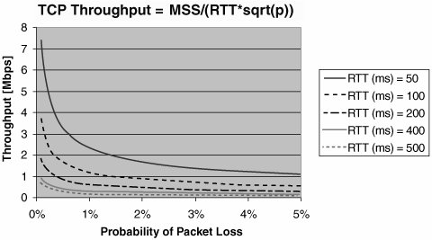
It is worth discussing each element in more detail. It is important to base performance characteristics on the requirements of the application being supported and to consider them from the point of view of end-to-end performance. Starting with PQ service, which will be used for voice, see Figure 10-1, which shows the results of ITU G.114 testing for voice quality performance. The E-model rating is simply a term given to a set of tests used to assess user satisfaction with the quality of a telephone call. Figure 10-1. SLA Metrics: One-Way Delay (VoIP)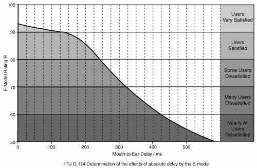 If you select a mouth-to-ear delay budget of 150 ms, you may determine that the codec and LAN delay may account for 50 ms, for example (this varies from network to network), leaving you 100 ms for the VPN. If the provider is managing the service to the CE, this is the performance statistic. However, if the provider is managing the service only to the PE, perhaps only 30 ms is acceptable to stay within the end-to-end budget. This more stringent requirement comes from the serialization times of the access link speed (for maximum-sized fragments), the PQ's queue depth, and the size of the first in, first out (FIFO) transmit ring on the routers in use as a PE, all taking up 35 ms for the ingress link and 35 ms for the egress link. Whether the provider manages from CE to CE or PE to PE, targets must be set for the connection type, and reports need to be delivered against contracted performance. From the enterprise perspective, it's simplest to have the provider measure and report on performance from CE to CE; however, that does come with a drawback. To do so, the provider must be able to control the CE for the purposes of setting up IP SLA probes to measure the CE-to-CE performance and collect statistics. This is generally done by having the provider manage the CE device. However, not all enterprises want the IOS revision on the CE to be controlled by the provider, because the enterprise might want to upgrade its routers to take advantage of a new IOS feature. Clearly, this needs to be negotiated between the provider and enterprise to reach the optimum solution for the network in question. For the data class, some research suggests that, for a user to retain his train of thought when using an application, the application needs to respond within one second (see Jakob Nielsen's Usability Engineering, published by Morgan Kaufmann, 1994). To reach this, it is reasonable to budget 700 ms for server-side processing and to require the end-to-end round-trip time to be less than 300 ms for the data classes. Jitter, or delay variation, is a concern for real-time applications. With today's newest IP phones, adaptive jitter buffers compensate for jitter within the network and automatically optimize their settings. This is done by effectively turning a variable delay into a fixed delay by having the buffer delay all packets for a length of time that allows the buffer to smooth out any variations in packet delivery. This reduces the need for tight bounds on jitter to be specified, as long as the fixed delays plus the variable delays are less than the overall delay budget. However, for older jitter buffers, the effects of jitter above 30 or 35 ms can be catastrophic in terms of meeting user expectations for voice or other real-time applications. Clearly, knowledge of your network's ability to deal with jitter is required to define appropriate performance characteristics for the WAN. The effects of loss are evident in both real-time and CBWFQ classes. For real time, it is possible for jitter buffers to use packet interpolation techniques to conceal the loss of 30 ms of voice samples. Given that a typical sample rate for voice is 20 ms, this tells you that a loss of two consecutive samples or more will cause a blip to be heard in the voice conversation that packet interpolation techniques cannot conceal. Assuming a random-drop distribution within a single voice flow, a 0.25-percent packet drop rate within the real-time class results in a loss every 53 minutes that cannot be concealed. The enterprise must decide whether this is acceptable or whether tighter, or less tight, loss characteristics are required. For the data classes, loss affects the attainable TCP throughput, as shown in Figure 10-2. Figure 10-2. TCP ThroughputGraph created based on information from "The Macroscopic Behavior of the TCP Congestion Avoidance Algorithm," Matthew Mathis, Computer Communication Review, July 1997. In Figure 10-2, you can see the maximum attainable TCP throughput for different packet-loss probabilities given different round-trip time characteristics. As long as the throughput per class, loss, and round-trip time fall within the performance envelopes illustrated, the network should perform as required. The primary reporting concern with the data classes is how well they perform for delay and throughput, which depends almost entirely on the load offered to them by the enterprise. Should the enterprise send more than what is contracted for and set up within a data class, the loss and delay grow exponentially, and the provider can't control this. Realistically, some sort of cooperative model between the provider and enterprise is required to ensure that data classes are not overloaded, or, if they are, that performance guarantees are expected only when the class is less than 100 percent utilized. Other subjects listed in the SLA are more straightforward. Availability, MTTR, and installation and upgrade performance are mostly self-explanatory:
Network Operations TrainingClearly, with a new infrastructure to support, system administrators need appropriate training in the technology itself, the procedures to use to turn up or troubleshoot new sites, and the tools they will have to assist them in their responsibilities. The question of whether to train the enterprise operations staff in the operation of MPLS VPNs (with respect to the service operation within the provider's network) is open. Some enterprises may decide that, because no MPLS encapsulation or MPLS protocols will be seen by the enterprise network operators, no training is necessary for this technology. However, experience to date has shown that when you troubleshoot issues with service provider staff, knowledge of MPLS VPN operation is helpful. The following high-level topics were taught to a large enterprise that successfully migrated network operations to a provider-delivered MPLS VPN service. These topics can be used as a template to evaluate training offerings to see if all necessary topics are covered:
These topics can be covered with course outlines that are similar to the following:
|
EAN: 2147483647
Pages: 136