Step 4: Define the Solution System Boundary
| Once the problem statement is agreed to and the users and stakeholders are identified, we can turn our attention to defining a system that can be deployed to address the problem. In so doing, we enter an important transition state wherein we have to keep two things in mind: an understanding of the problem and the considerations of a potential solution. The next important step is to determine the boundaries of the solution system. The system boundary defines the border between the solution and the real world that surrounds the solution (Figure 5-4). In other words, the system boundary describes an envelope in which the solution system is contained. Information, in the form of inputs and outputs, is passed back and forth from the system to the users living outside the system. All interactions with the system occur via interfaces between the system and the external world. Figure 5-4. The inputs/system/outputs relationship
In other words, if we are going to have to build it or modify it, it's part of our solution and within the boundary; if not, it's external to our system. Thus, we divide the world into two interesting classes of things:
Let's identify the "things that interact with our system" generically as "actors on our system." After all, they do have a role to play in making our system do its thing. We'll represent an actor with a simple stick figure icon. We'll define an actor as
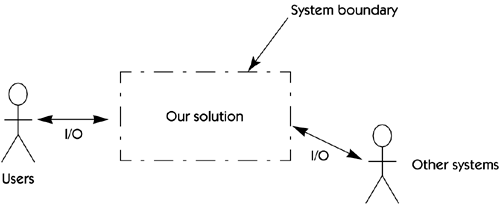
Once we understand the concept of an actor, we can illustrate a system boundary as shown in Figure 5-5. Figure 5-5. System boundary In many cases, the boundaries of the system are obvious. For example, a single- user , shrink-wrap personal contact manager that runs on a stand-alone Windows 2000 platform has relatively well-defined boundaries. There is only one user and one platform. The interfaces between the user and the application consist of the interface dialogs the user uses to access information in the system and any output reports and communication paths the system uses to document or transmit that information. In our order entry system example, which is to be integrated into an existing legacy system, the boundaries are not so clear. The analyst must determine whether data is shared with other applications, whether the new application is to be distributed across various hosts or clients , and who the users are. For example, should the production people have online access to sales orders? Is there a quality control or audit function to be provided? Will the system run on the mainframe or on a new client/server front end? Will specialized management reports be provided? Although it seems fairly obvious, identifying the actors is a key analytical step in problem analysis. How do we find these actors? Here are some helpful questions to ask.
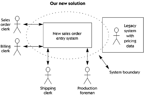
With the answers to these questions in hand, the analyst can now create a "system perspective," a block diagram that describes the boundaries of the system, the users, and other interfaces. Figure 5-6 provides a simplified system perspective for the new sales order system. Figure 5-6. System perspective The dotted line illustrates the system boundary for the proposed solution. The diagram shows that the bulk of the new application will be deployed on the new sales order entry system but a portion of the solution code must be developed and deployed on the existing legacy system. In other words, in order to solve our problem we will have to both develop a new system (new sales order entry system) and modify some elements of the existing system (legacy system). |
EAN: N/A
Pages: 257


