Decision Tables and Decision Trees
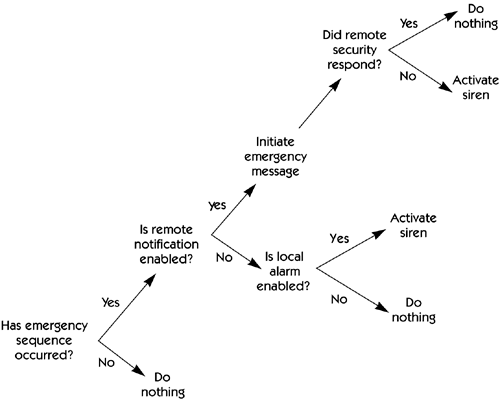
| It's common to see a requirement that deals with a combination of inputs; different combinations of those inputs lead to different behaviors or outputs. Suppose, for example, that we have a system with five inputs ”A, B, C, D, and E ”and we see a requirement that starts with a pseudocode-like statement: "If A is true, then if B and C are also true, generate output X, unless E is true, in which case the required output is Y." The combination of IF-THEN-ELSE clauses quickly becomes tangled, especially if, as in this example, it involves nested IF s. Typically, nontechnical users are not sure that they understand any of it, and nobody is sure whether all the possible combinations and permutations of A, B, C, D, and E have been covered. The solution in this case is to enumerate all the combinations of inputs and to describe each one explicitly in a decision table . In our example, if the only permissible values of the inputs are "true" and "false," we have 2 5 , or 32, combinations. These can be represented in a table containing 5 rows ”one for each input variable ”and 32 columns . Alternatively, a decision tree can be drawn to portray the same information. Figure 24-3 shows a decision tree used to describe the HOLIS emergency sequence. Figure 24-3. Example of a graphical decision tree |
EAN: N/A
Pages: 257
- The Second Wave ERP Market: An Australian Viewpoint
- Enterprise Application Integration: New Solutions for a Solved Problem or a Challenging Research Field?
- Data Mining for Business Process Reengineering
- A Hybrid Clustering Technique to Improve Patient Data Quality
- Development of Interactive Web Sites to Enhance Police/Community Relations
