Database Design and Implementation
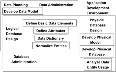
| Figure 4-7 shows the many facets to work on when implementing a DB2 relational database. A couple of general design steps need to be performed: development of a logical model and development/implementation of a physical model. Figure 4-7. Designing relational database applications
Logical DesignLogical design is the process of determining entities, entity attributes, relationships among entities, degrees of the relationships, and representing them in a fully keyed, normalized data model or entity relationship diagram. The normalized data model can then be used to define the tables needed for the relational database. Performing the logical design also involves identifying primary keys and foreign keys. A data model is a graphic, conceptual model that identifies the entity types of the business and the business interactions among the entities. The data model provides a static rather than dynamic view of data, which appears as if frozen in time. Two basic approaches to designing a data model follow.
A logical data model has three basic components: entities, attributes, and relationships. EntitiesAn entity is an object about which we store data for the purpose of answering a query or making a decision. An entity may be a person, place, or thingeventof interest to the enterprise or application. Occurrences of an entity are uniquely identified by one or more attributes that make up the key to the data entity. An entity is often named with a singular noun, such as Customer. In addition, an association (relationship) between two or more data entities represents an action and may be defined in an English sentence: subject, verb. This interaction is directional:
AttributesAttributes are the values, or characteristics, associated with an entity. Every occurrence of an entity has associated attributes. Attributes can be represented as a field. Domains are also used to give specific property of an object. An attribute that has attributes should be considered as a possible entity. Attributes are the data items required to make process work. When identifying attributes, consider such characteristics as data type, size, how used, and entities to which related. NormalizationNormalization is the process of nonloss decomposition of data relations and is performed during logical database design. Normalization promotes the formalization of simple ideas, such as "Domains must contain atomic values (single value)." The concept of functional dependence plays a key role. It is a helpful tool for physical design but is not an absolute and does not result in a physical design (final table design). Many process considerations must be accounted for before a physical design is done. Some of the advantages of a normalized design may include
Some of the objectives of data normalization are
Depending on the interpretation of the relational model, the normal forms may vary but in general number five. We look only at three, as most normalized designs are in the third normal form. Figure 4-8 shows the first normal form (1NF), which has the following characteristics.
Figure 4-8. First normal form
Figure 4-9 shows the second normal form (2NF), which has the following characteristics.
Figure 4-9. Second normal form
Figure 4-10 shows the third normal form (3NF), which has the following characteristics.
Figure 4-10. Third normal form
AnomoliesThe introduction of data anomalies into a database design can lower productivity in application design and create useless data. Anomolies need to be eliminated in order to
Anomalies can cause
Figure 4-11a shows what an update anomaly is and a problem that could result. Figure 4-11b shows how a normalized design would fix the issue. Figure 4-11. (a) Update anomaly; (b) Normalized design to solve update anomaly
Physical DesignThe physical-data model is similar to the logical-data model except that the objects are identified as physical objects ready to be implemented in a DB2 environment. All elements on the logical model should transform into an object on the physical model. At this point, the model should be normalized. Following are some general guidelines for transforming a logical model to a physical one:
Performance and DBMS specifics must still be considered afterward. Example ImplementationThe best way to understand data type selection is to design a database and implement the design by using DB2. This example implementation creates a database that can be used to schedule and track the results of a certification program. This database will be used to illustrate many aspects of SQL and DB2 features. Many examples from this database will be used throughout this book. NOTE This database was developed in the DB2 Universal Database V8 for Linux, UNIX, and Windows Database Administration Certification Guide, Fifth Edition, published by Prentice Hall, and can be referenced in that publication to observe implementation differences between DB2 z/OS and the DB2 UNIX, Windows, and Linux platforms. This database will be used to schedule test candidates' exams; following candidates' completion of the test, the database will contain the candidates' test scores. The database and its application will need to perform eight tasks:
The database will be named DB2CERT. The data to be stored in the DB2CERT database can easily be grouped into three reference tables; a fourth table is used to relate the other tables. The primary relationship can be defined as a test candidate takes a specific test at a test center. Figure 4-12 shows the relationships within the problem domain. The rectangles represent the base tables: CANDIDATE, TEST_CENTER, and TEST. The fourth table is a relationship table called TEST_TAKEN. DB2CERT Database Table DescriptionsThe following tables will be used in the DB2CERT database.
Once the tables and their relationships have been defined, the following should be defined:
Figure 4-13 shows the database design. The rectangles represent the entities, or tables. The columns, or attributes, are listed by the entities. Note that some of the columns are derived columns; that is, they represent a concept, not a physical attribute of an object. The derived columns (such as TOTALTAKEN on TEST) are included in the model because their values will be populated by the database, using a constraint mechanism. Figure 4-13. Entities and attributes
We must map the attributes shown in Figure 4-13 as DB2-supported data types or distinct types. To demonstrate some of the powerful features of DB2, we have decided to create distinct types for many of the attributes. It is beneficial to have a primary key defined for each table to ensure uniqueness of the data records. The attributes that are bolded will be used as primary keys. We will also create unique keys to illustrate their use. Earlier, we mentioned that the DB2CERT database will have four tables. However, the design shown in Figure 4-14 has only three tables defined, shown as rectangles. Figure 4-14. DB2 Certification database entity basic relationship
An implied table is defined in the relationship candidate takes a test. A table is required to store each occurrence of a candidate taking a certification test. A restriction will be imposed on the candidates: They can take the test only once on any given day. A candidate can take different tests on the same day but not the same test. With this restriction in place, we will define a primary key for the TEST_TAKEN table as a composite key including NUMBER (test ID), CID (candidate ID), and DATE_TAKEN (the date of the test). By defining the primary key as a combination of these three values, this constraint can be enforced. Figure 4-14 shows the entity relationship diagrams for the Certification database. Figure 4-15 shows the RI relationships between the tables in the Certification database. Figure 4-15. DB2 Certification database referential integrity
The diamond shapes are used to describe the relationships between the tables, including the parent/child relationship. For example, the CANDIDATE and the TEST_TAKEN table have a one-to-many relationship because a single candidate can take many tests. This relationship is shown by denoting the values of 1 and M (many) on the appropriate side of the diamond. The database design shown in Figure 4-14 is just one type of diagramming technique. A logical database design can be represented in a number of ways, but it should not absolutely dictate the physical implementation of the database. It has been included it here because it will be used in many of the SQL statements throughout the rest of the book. Defining Distinct TypesDistinct types must exist in the database before they can be referenced in a CREATE TABLE statement. We created a numeric distinct type of MINUTES; a character distinct type of PHONE; and a binary large object distinct type of BITMAP. CREATE DISTINCT TYPE phone AS CHAR(10) WITH COMPARISONS; CREATE DISTINCT TYPE bitmap AS BLOB(INT) WITH COMPARISONS; CREATE DISTINCT TYPE minutes AS SMALLINT WITH COMPARISONS; Defining Tables and ColumnsDesigning a database involves many considerations, only a few of which are discussed in this book. Using the database design in Figure 4-13, we can start creating database objects. The first step in creating a database is to issue the run a CREATE DATABASE statement, such as the following: CREATE DATABASE CERTTS STOGROUP CERTSTG BUFFERPOOL BP7 INDEXBP BP8; Once the database has been created, dependent physical objects can be created. Distinct (user-defined) data types can also be created. Tables can then be created. (If explicit table spaces are to be used, they will need to be created first, but for this example, we will assume they already exist. Refer to Appendix A for more table space CREATE methods.) The database design has a number of attributes shown. Each of these attributes will be a column in the table definitions. Every DB2 table contains one or more columns. The tables and their corresponding columns are given names. Data is placed in a DB2 table by using the SQL statement INSERT or UPDATE. (The LOAD utility is also an option.) Usually, it is desirable for each column, or data value, to have a value. Sometimes, no value is provided for a column during the INSERT statement. If the column is defined as NOT NULL, the INSERT statement will fail. If a default value is defined, it will be stored. The table being created in the following DDL is called DB2USER1.CANDIDATE and contains 15 columns. Each column is given a name and a data type. Two distinct data types are being used in the DB2USER1.CANDIDATE table. These data types are PHONE and BITMAP. In addition, constraints are defined for the valid values for some of the columns. For example, the null constraint is specified for all the columns except HPHONE, WPHONE, INITIAL, and PHOTO. CREATE TABLE DB2USER1.CANDIDATE ( Cid CHAR(9) NOT NULL, LName VARCHAR(30) NOT NULL, FName VARCHAR(30) NOT NULL, Initial CHAR(1), HPhone phone, WPhone phone, StreetNo VARCHAR(8) NOT NULL, StreetName VARCHAR(20) NOT NULL, City VARCHAR(30) NOT NULL, Prov_State VARCHAR(30) NOT NULL, Code CHAR(6) NOT NULL, Country VARCHAR(20)) NOT NULL, Cert_DBA CHAR(1) NOT NULL WITH DEFAULT 'N', Cert_APP CHAR(1) NOT NULL WITH DEFAULT 'N', PHOTO BITMAP, PRIMARY KEY (Cid)) IN DB2CERT.CERTTS; KeysKeys are a special set of columns defined on a table. They can be used to uniquely identify a row or to reference a uniquely identified row from another table. Keys can be classified either by the columns they comprise or by the database constraint they support. See the discussion earlier in this chapter on types of keys. Defining Primary KeysIt is sometimes beneficial to define a primary key for each of your DB2 tables to guarantee the uniqueness of a column value or group of column values (composite key). In the previous CREATE statement, the primary key for the table candidate is defined as the column CID (candidate ID). By specifying this column as a primary key, DB2 will create a system-unique index if one does not already exist. Let us look at the other tables representing the tests and the test centers. In the following CREATE statements, the TEST and TEST_CENTER tables are shown. These tables each have a primary key defined. In our example, the primary-key constraint was given a name (UNIQUE_TEST and UNIQUE_CENTER) for referencing purposes. If a constraint name is not provided, DB2 will assign a system-generated name to the constraint. CREATE TABLE DB2USER1.TEST ( NUMBER CHAR(6) NOT NULL, NAME VARCHAR(50) NOT NULL, TYPE CHAR(1) NOT NULL, Cut_Score DECIMAL(6,2) NOT NULL, Length minutes NOT NULL, TotalTaken SMALLINT NOT NULL, TotalPassed SMALLINT NOT NULL, CONSTRAINT Unique_Test PRIMARY KEY(Number), CONSTRAINT Unique_Test_Name UNIQUE (Name) CONSTRAINT Test_Type CHECK (Type IN ('P','B'))) IN DB2CERT.CERTTS CREATE TABLE DB2USER1.TEST.CENTER ( Tcid CHAR(6) NOT NULL, Name VARCHAR(40) NOT NULL, StreetNo VARCHAR(8) NOT NULL, StreetName VARCHAR(20) NOT NULL, City VARCHAR(30) NOT NULL, Prov_State VARCHAR(30) NOT NULL, Country VARCHAR(20) NOT NULL, Code CHAR(6) NOT NULL, Type CHAR(1) NOT NULL, Phone phone NOT NULL, No_Seats SMALLINT NOT NULL, CONSTRAINT Unique_Center PRIMARY KEY (Tcid)) IN DB2CERT.CERTTS PARTITION BY (TCID) (PARTITION 1 ENDING AT ('300'), PARTITION 2 ENDING AT ('500')); Note that the TEST_CENTER table is a partitioned table that is partitioned by TCID. Defining Unique KeysUnique keys can be used to enforce uniqueness on a set of columns. A table can have more than one unique key (index) defined. The TEST table definition uses a unique constraint (UNIQUE_TEST_NAME) on column NAME to ensure that a test name is not used twice. The column NUMBER too has a primary-key constraint to avoid duplicate test numbers. Having unique constraints on more than one set of columns of a table is different from defining a composite unique key that includes the whole set of columns. For example, even if we define a composite primary key on the columns NUMBER and NAME, a test name may still be duplicated using a different test number. NOTE A unique index needs to always be created for primaryif one does not already existor unique-key constraints, unless using the schema processor. If you define a constraint name, it will be used to name the index; otherwise, a system-generated name will be used for the index. Defining Foreign KeysA foreign key is a reference to the data values in another table. Foreign keys have various types of constraints. Let us look at the remaining table in the DB2 Certification database and, in particular, its foreign-key constraints. We have one composite primary key defined and three foreign-key constraints. The primary key is defined as the columns CID, TCID, and NUMBER on the TEST_TAKEN table. The foreign-key constraints will perform the following.
NOTE A foreign-key constraint always relates to the primary or unique constraint of the table in the references clause. CREATE TABLE DB2USER1.TEST_TAKEN ( Cid candidate_id NOT NULL, Tcid center_id NOT NULL, Number test_id NOT NULL, Date_Taken date NOT NULL WITH DEFAULT, Start_Time TIME NOT NULL, Finish_Time TIME NOT NULL, Score score, Seat_No CHAR(2) NOT NULL, CONSTRAINT number_const PRIMARY KEY (Cid,Tcid,Number), FOREIGN KEY (Cid) REFERENCES db2cert.candidate ON DELETE CASCADE, FOREIGN KEY (Tcid) REFERENCES db2cert.test_center ON DELETE CASCADE, FOREIGN KEY (Number) REFERENCES db2cert.test ON DELETE RESTRICT) IN DB2CERT.CERTTS Defining parent/child relationships between tables is known as declarative referential integrity because the child table refers to the parent table. These constraints are defined during table creation or by using the ALTER TABLE SQL statement. DB2 will enforce referential constraints for all INSERT, UPDATE, and DELETE activity. NOTE This database implementation created only the tables and distinct types. The complete DDL for the storage group, databases, table spaces, tables, and indexes can be found in Appendix A. |


EAN: 2147483647
Pages: 175
- Chapter II Information Search on the Internet: A Causal Model
- Chapter VIII Personalization Systems and Their Deployment as Web Site Interface Design Decisions
- Chapter XVI Turning Web Surfers into Loyal Customers: Cognitive Lock-In Through Interface Design and Web Site Usability
- Chapter XVII Internet Markets and E-Loyalty
- Chapter XVIII Web Systems Design, Litigation, and Online Consumer Behavior