TCPIP Model
TCP/IP Model
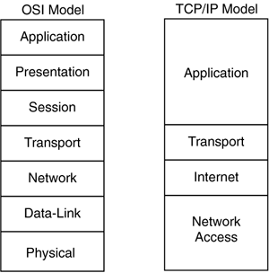
The TCP/IP model does not match the seven layers of the Open System Interconnection (OSI) model. There is no universal agreement regarding how to describe TCP/IP with a layered model, but it is agreed that there are fewer layers than the OSI model. TCP/IP is often described as having four layers, as illustrated in the following figure (see Figure 3-1).
Figure 3-1. OSI Model and TCP/IP Model Layers

The following list describes each TCP/IP layer in relation to the OSI Network Model layers:
Application Layer In TCP/IP, the Application layer also includes the OSI Presentation layer and Session layer. Any process occurring above the Transport layer is considered to be part of the Application layer.
In TCP/IP, the terms socket and port describe the path over which applications communicate. There are numerous application level protocols in TCP/IP, including Simple Mail Transfer Protocol (SMTP) and Post Office Protocol (POP) used for e-mail, Hyper Text Transfer Protocol (HTTP) used for the World Wide Web, and File Transfer Protocol (FTP). Most application level protocols are associated with one or more port numbers.
Transport Layer There are two Transport layer protocols:
- Transmission Control Protocol (TCP) guarantees that information is received as it was sent.
- User Datagram Protocol (UDP) performs no end-to-end reliability checks.
Internet Layer The OSI Network Model layer isolates the upper-layer protocols from the details of the underlying network (lower layers) and manages the connections across the network. All upper- and lowerlayer communication passes through IP as it is passed through the TCP/IP protocol stack.
Network Access Layer The OSI Model DataLink layer and Physical layer are grouped together. TCP/IP makes use of existing DataLink and Physical layer standards instead of defining its own.
The fourlayer structure of TCP/IP is built as information is passed down from applications to the Physical network layer. When data is sent from a source, each layer treats all of the information it receives from the upper layer as data. Control information is added to the front of this data (header), and error checksum information is added to the rear (trailer). This process is known as encapsulation and is illustrated in Figure 3-2.
Figure 3-2. TCP/IP Encapsulation

When data is received, the opposite procedure takes place as each layer removes its header before passing the data to the layer above.
EAN: 2147483647
Pages: 269